
Abstract
Ultrasonic consolidation has been shown to be a viable metal-matrix-based smart composite additive layer manufacturing process. Yet, high quantity fibre integration has presented the requirement for a method of accurate positioning and fibre protection to maintain the fibre layout during ultrasonic consolidation. This study presents a novel approach for fibre integration during ultrasonic consolidation: channels are manufactured by laser processing on an ultrasonically consolidated sample. At the same time, controlled melt ejection is applied to aid accurate fibre placement and simultaneously reducing fibre damage occurrences. Microscopic, scanning electron microscopic and energy dispersive X-ray spectroscopic analyses are used for samples containing up to 10.5% fibres, one of the highest volumes in an ultrasonically consolidated composite so far. Up to 98% of the fibres remain in the channels after consolidation and fibre damage is reduced to less than 2% per sample. This study furthers the knowledge of high volume fibre embedment via ultrasonic consolidation for future smart material manufacturing.
Introduction
Ultrasonic consolidation (UC) is an additive manufacturing method based on the ultrasonic welding of a sequence of metal foils. The process is suited to produce complex 3D metal parts by combining ultrasonic metal welding and computer numerical control (CNC) milling techniques. 1 A schematic overview of the process is given in Figure 1(a) and (b). The theory for bond formation that has the most consensus is currently atomic bonding2,3 and is displayed in Figure 1(c)–(e). The foil surfaces, comprising of oxide layers and asperities, are brought into contact by the contact pressure of the sonotrode and anvil. The oscillating shear forces generate friction at the interface which causes the impure surface structures to be broken-up and dispersed along the weld line. Plastic deformation causes new material to be extruded from underneath which forms the metallurgical bond.
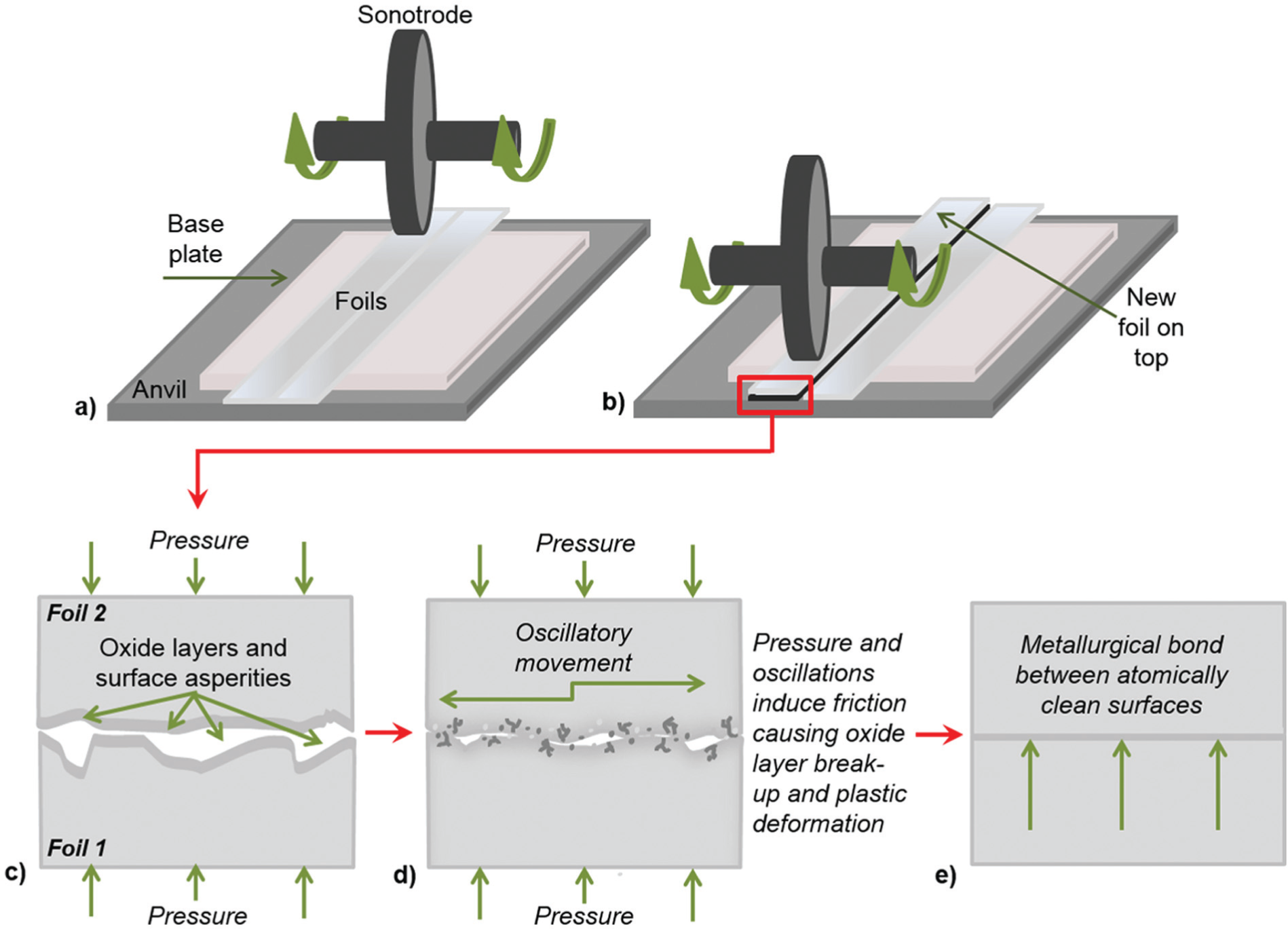
Schematic presentation of the UC process: (a) initial welding of foils, (b) welding of foil on top of initial foil and (c)–(e) schematic representation of the bond development at the interface.
Previous research has demonstrated the possibility to embed different fibre types within UC metal matrices 2 to create smart material structures. The UC process benefits from two key advantages which help to overcome limitations such as high pressures, high temperatures and interfacial reactions which have been observed in well-established metal matrix composite (MMC) manufacturing techniques such as hot isostatic pressing, diffusion bonding or thermal spraying. 4 The first advantage is that bonding between adjacent metal foils is accomplished at temperatures much lower than the melting temperature of the foil material (typically ≤50%). 5 Second, the ultrasonic excitation of the metal foil reduces the static yield stress within the material and induces highly localised plastic flow.3,6
Successful fibre integration has been demonstrated for silicon carbide (SiC), shape memory alloy (SMA) and optical fibres.2,7–10 The bond formation process was demonstrated to be stronger for higher amplitudes and contact pressures.2,5,8 Consequently, low pressures and amplitudes entailed unbonded surfaces without encapsulation of the fibres or even separation of the foils. However, higher amplitudes and contact pressures led to distortion and displacement of fibres.9,11 For efficient smart material fabrication, higher volume fractions of fibres would be needed for efficient controlling, sensing and actuating. Until now, research on high fibre volume integration has shown that the delivery of sufficient energy to the interfaces was insufficient and led to poor bonding quality.7,12,13 To approach high volume fibre integration without high amplitudes yet reducing the required amount of plastic flow and secure and accurate placement of the fibres, a method based on creating trenches in post-UC samples via a laser was pursued. Figure 2 displays the schematic representation of the proposed method. A UC metal substrate was irradiated using a laser to create a channel (Figure 2(a)). The generated molten material was used to be distributed on the sides of the channel to create raised shoulder features (Figure 2(b)). The shoulders were intended to reduce the required level of plastic flow and enhance encapsulation during consolidation of fibres (Figure 2(c)). The channel itself was intended to securely position the fibres during UC. In Figure 2(c), the intended channel and the shoulder geometry are displayed. The geometry was determined as a result of the to-be embedded fibre diameters (100 μm). In Figure 2(d), the final embedded fibre and the UC process are shown.
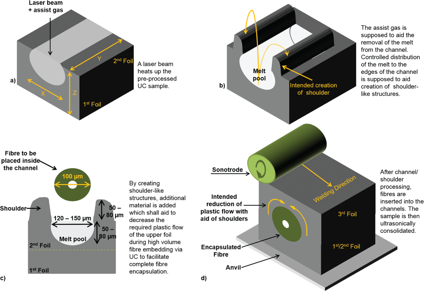
Proposed approach to allow accurate placement and sufficient encapsulation of fibres: a) UC metal substrate is irradiated using a laser to create a channel, b) molten material is distributed to the sides of the channel to create raised shoulder features, c) channel and shoulder features with fibre to show the relative scale of the features and d) fibre is placed in channel and UC bonds upper foil and embeds the fibre.
In this study, the placement and the integrity of SiC fibres placed into the pre-processed laser channels after UC were investigated. Multiple fibres (24) were embedded to investigate the aid of the channels for high volume fibre encapsulation. The authors examined the aid of the channels for accurate fibre placement as well as their integrity after consolidation and the influence of the channel on fibre behaviour.
Methodology
UC sample manufacture
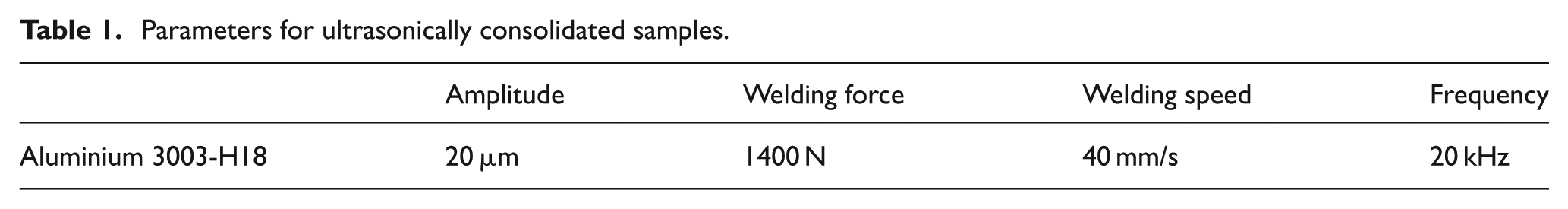
Al 3003-H18 foil (United Aluminum Corporation, North Haven, Connecticut, USA) with a thickness of 100 μm and a width of 25.4 mm was selected as the UC matrix material. Earlier use of the material allowed a comparison of the aid of channels for fibre insertion. 14 Prior to laser machining, UC samples were manufactured using the Alpha 2 UC machine supplied by Solidica Inc. (Ann Arbor, Michigan, USA). The sample production process was similar to that shown in Figure 1. First, an Al 3003-H18 foil was consolidated to an Al 1050 plate (330 × 29 × 1 mm) (Alcoa Inc., UK). A second Al 3003-H18 foil was then bonded to the first one to increase the sample thickness (200 μm) prior to laser processing. The parameters used for consolidation of the foils can be seen in Table 1. The UC samples were manufactured at room temperature in an open environment due to an open cabinet.
Parameters for ultrasonically consolidated samples.
Channel processing
Channel processing in post-UC samples was carried out with two different lasers: an SPI 200 W fibre laser and a Trumpf TruFiber 300 W laser. The main laser specifications are detailed in Table 2.
Main laser specifications.
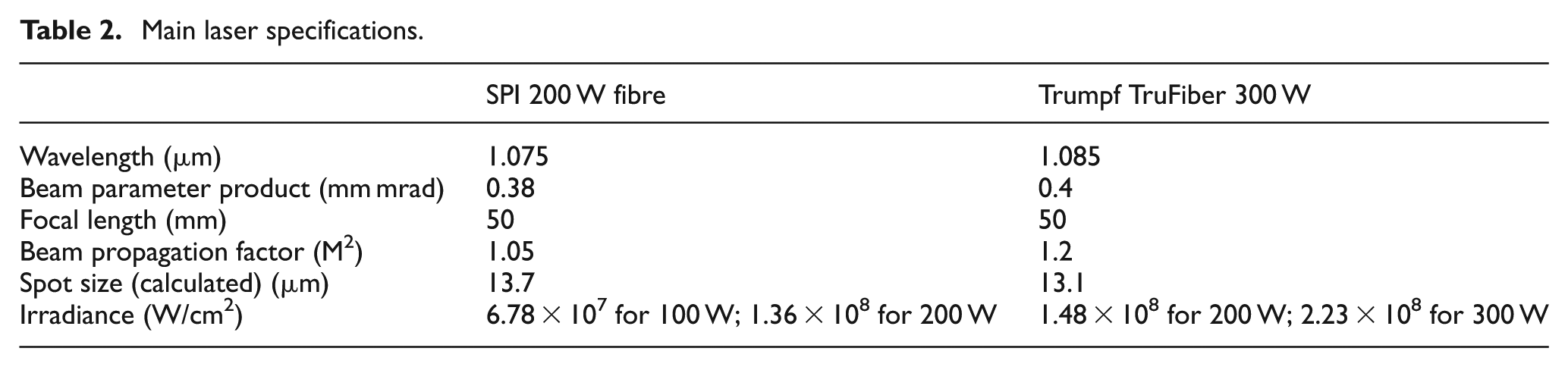
Two different fibre lasers were used as the Trumpf TruFiber 300 W laser exhibited a higher power range compared to the SPI 200 W fibre laser. Hence, channels manufactured with the Trumpf TruFiber 300 W laser were shown to exhibit a greater channel depth and higher shoulder features than samples produced by the SPI 200 W fibre laser (Figure 3). Comparison of the channel depth was considered important for data comparison for effective fibre encapsulation. Additionally, two assist gas types (air and nitrogen) were used for the two lasers in order to compare their influence of the assist gas on UC bond formation in future work. Furthermore, air as an assist gas added an extra ignition source due to the oxygen content which was expected to aid deep channel production.
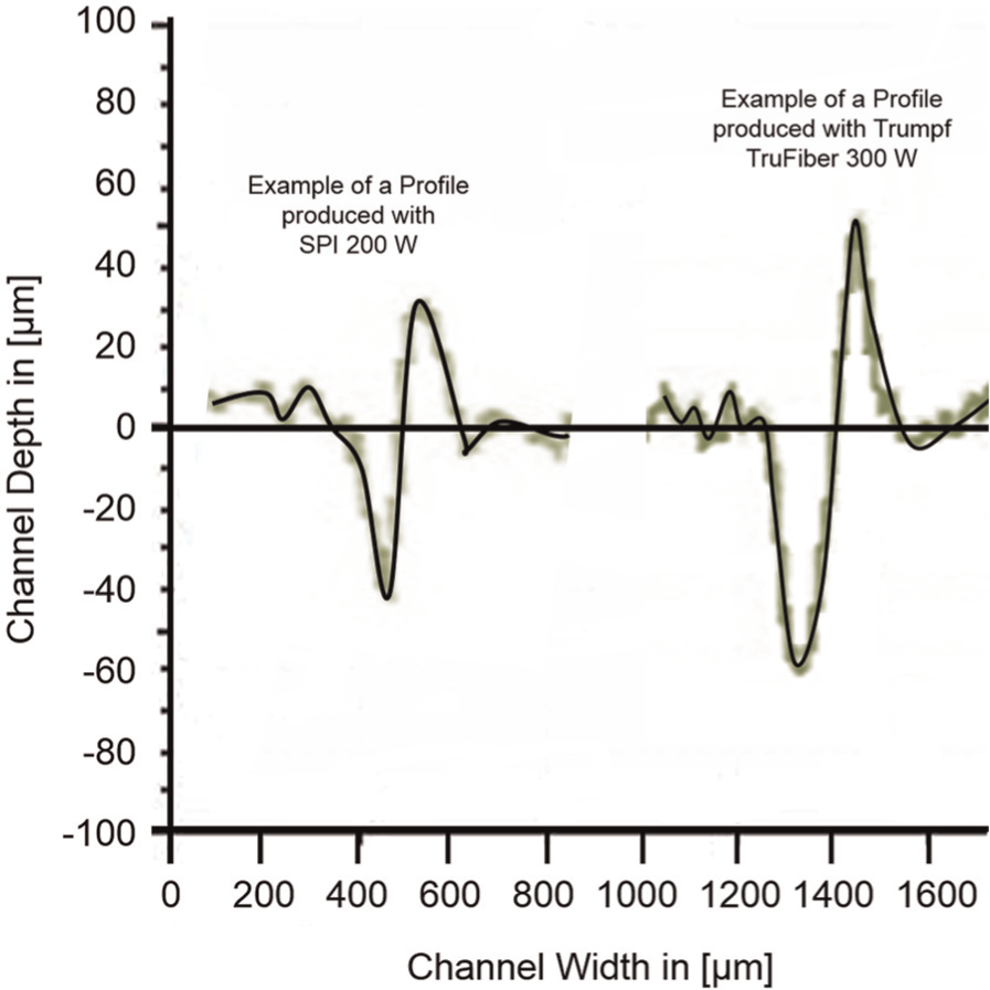
Examples of different channel profiles for SPI 200 W and Trumpf TruFiber 300 W.
Fibre lasers as the laser source were chosen due to the excellent beam quality, the nearly diffraction-limited beam and high brightness, which allowed focusing of the laser to small spot sizes and hence, a high power density input (Table 2) which was necessary as aluminium exhibits a high reflection coefficient and high thermal conductivity.15–18 The nearly diffraction-limited beam allowed a Gaussian-shaped heat input into the material. It was proposed that higher-order modes would modify the heat input into the material, which could possibly make the flow pattern of the melted material more difficult to control. 19
The channel production process has been described elsewhere. 20 The samples for the SPI 200 W fibre laser were processed using a power of 140 W, a speed of 275 mm/min and a nitrogen gas pressure of 0.6 MPa. The samples for the Trumpf TruFiber 300 W laser were processed using a power of 250 W, a traverse speed of 200 mm/min and an air gas pressure of 0.8 MPa. The parameters were chosen as they had previously shown the best results for fibre embedding in UC. 20 Channels manufactured with the SPI 200 W fibre laser exhibited a depth of 40–60 μm and channels manufactured with the Trumpf TruFiber 300 W laser exhibited a depth of 65–80 μm. The depth was measured using a 2 μm inductive gauge (Talysurf CLI 2000; Taylor Hobson Ltd. Leicester, UK) to allow for direct examination. An example of the profile obtained by samples manufactured by the SPI laser and an example of the profile manufactured by the Trumpf laser can be seen in Figure 3.
The profile from Figure 3 indicates that the shoulder feature only appears on one side of the created channel. This was due to the flow of the melt and has been previously discussed. 20 In order to explore the influences of the channel, one-sided shoulder and fibre orientation, which would possibly influence plastic flow behaviour and bond formation during UC, 8 samples containing channels perpendicular and parallel to the welding direction were considered. In Figure 4, both channel types are displayed.
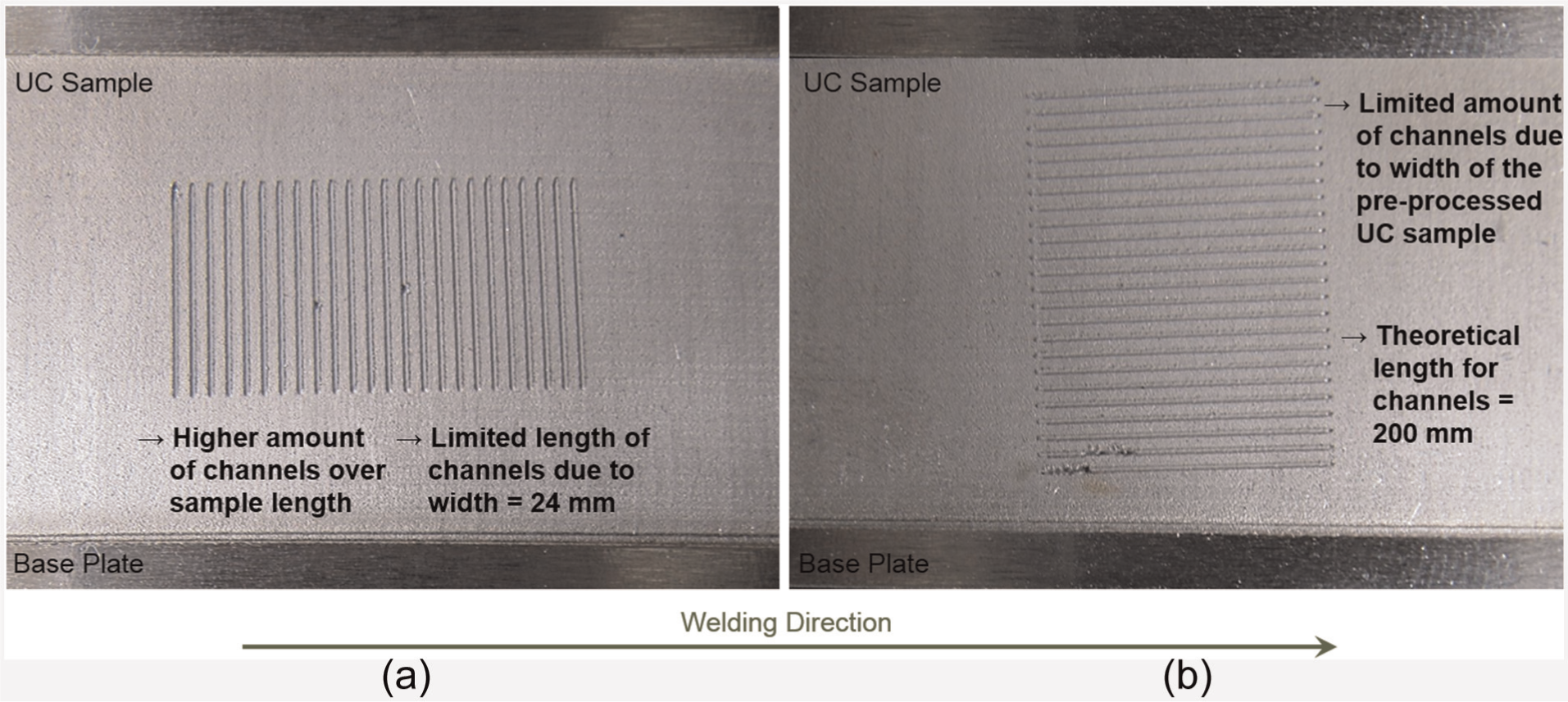
Example of 24 channels manufactured perpendicular to the UC welding direction (a) and parallel to the welding direction (b).
For channels produced in parallel direction, the width of the UC sample (24 mm) limited the amount of channels and shoulders to be produced without interference. Channel production perpendicular to the welding direction limited the length of the channels. Due to these limitations, samples containing 24 channels with a length of 15 mm were produced. The distance between the channels was set to 750 μm – measured from the starting point of the laser to the edge of the next channel – for samples manufactured with the SPI 200 W laser. Samples manufactured with the Trumpf TruFiber 300 W laser had a distance of 800 μm as the channels exhibited a greater width. 20 The gap of 750 μm and 800 μm was expected to be necessary to allow a sufficiently large area for bonding of the unprocessed foil material during UC.
Fibre embedding
To examine the aid of channels and shoulders in terms of fibre positioning and fibre integrity after UC, SiC sigma fibres (SM-1240; QinetiQ, Farnborough, UK) were selected. The fibre consisted of a 10 μm tungsten core and an outer diameter of 100 μm, with a double surface coating of approximately 1 μm titanium boride and 1 μm carbon. The hard nature and high strength of the SiC fibre allowed minimal fibre distortion. A schematic arrangement of the fibre embedding procedure is displayed in Figure 5. The SiC fibres were placed in the channels and held in place by applying adhesive tape (Figure 5(a)). The adhesive tape was applied approximately 1 mm from the end of the channel edges to avoid interference with the fibre embedding analysis. The sample was then placed on the anvil of the UC machine (Figure 5(b)). For samples containing perpendicular channels, the sample was placed with the shoulder in front of the fibre so that the shoulder would be consolidated first before the sonotrode can reach the fibre. Then, a strip of Al 3003-H18 foil was placed over the fibres (Figure 5(c)).
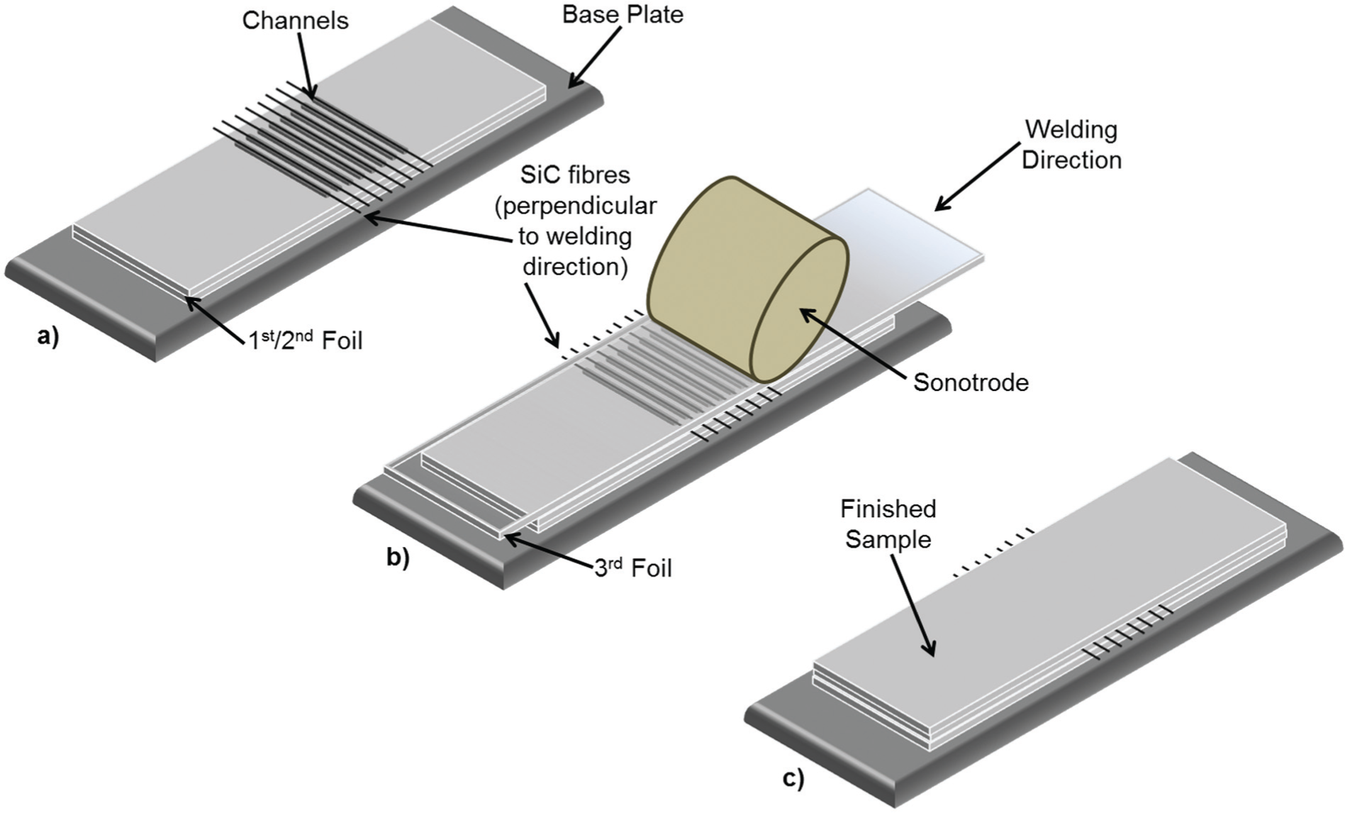
Embedding of fibres within Al 3003-H18 foils: (a) fibre placement, (b) welding of third foil and (c) sample with embedded fibres.
The foil was consolidated using the same parameters as stated in Table 1. The fibre sample manufacturing was carried out for samples produced by both lasers. Three samples (each containing 24 fibres which corresponds to 10.9 vol%) for each fibre orientation were produced with the SPI laser and nitrogen (referred to as SPI samples). For the Trumpf laser and air (referred to as Trumpf samples), five samples, also containing 24 fibres (corresponding to 10.2 vol%), were manufactured for each fibre orientation due to an increased depth.
Microstructural analysis of the samples
To analyse the samples, cross-sectioning of the samples was executed perpendicular to the channel direction with a diamond blade (Series 15HC, Diamond & Isomet Low Speed Saw (Buehler, Düsseldorf, Germany)) to avoid any possible cutting-induced fibre damage. The samples were mounted into Konductomet II (Buehler, Düsseldorf, Germany). The surface was ground to a surface finish of 1 μm Ra and then polished with colloidal silica to a surface finish of 0.1 μm Ra. Optical microscopy was conducted using an Olympus BX 60M microscope equipped with a MicroPublisher 3.3 RTV digital camera (Olympus, Southend-on-Sea, UK). A magnification of 100× was used.
To determine the aid of the channels for accurate positioning and to analyse the fibre appearance post-UC in greater detail, a Carl Zeiss 1530VP (Leo, Cambridge, UK) scanning electron microscope (SEM) was used. To analyse the position of the fibres post-UC, the distance between the centres of two fibre cores was measured. The fibre core of a SiC fibre appeared as a bright point during SEM and was therefore readily distinguishable. Measurements were carried out using point-to-point analysis with the LEO 32 user interface which allowed accurate measurement of the distance between the fibre cores. Distance measurement was carried out for three samples (72 fibres) in perpendicular and three samples (72 fibres) in parallel direction for each gas type. As the channel distances were set to 750 and 800 μm, the distance between the fibres cores was intended to be in the same range as fibres that had a diameter of 100 μm. The average values for the three samples in parallel and the three samples in perpendicular direction were then compared to each other. To analyse the fibre appearance post-UC, fibres were inspected using different magnifications. Energy dispersive X-ray spectroscopy (EDX) maps were taken to specify the main elements for alloy and fibre. The EDX was integrated in the SEM and an Oxford Instruments X-Max 80 mm2 detector was used. The beam current was set to 20 keV.
Results and discussion
Accurate positioning of fibres
Analysis of accurate positioning of fibres after UC was carried out in order to determine the assistance of the channels (and shoulders) from preventing rolling or movement of fibres during UC. When embedding high quantities of fibres, movement or rolling is not desirable as fibres may come into contact with each other or prohibit sufficient bonding area between the foils.
The average distances of the three parallel and the three perpendicular samples manufactured with the SPI laser are shown in Figure 6. The average distance for all samples containing fibres placed in parallel direction was 722 μm. The average distance for all perpendicular samples were similar (724 μm), yet lower than the original distance set between the fibres (750 μm). It can be seen from Figure 6 that the average values alternated around the mean average. However, the average of the perpendicularly embedded fibres ranged in a wider distance (560–820 μm) than parallel embedded fibres (655–800 μm). Hence, fibres embedded in parallel direction were less likely to move than perpendicularly embedded fibres.
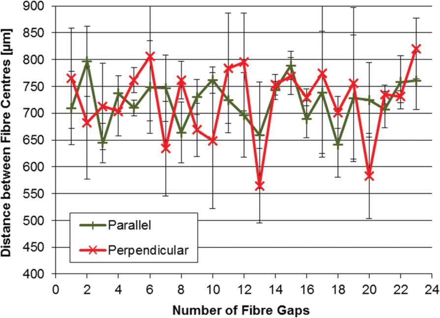
Average distance between fibre cores for both orientations (SPI 200 W; nitrogen).
The average distances of the five parallel and the five perpendicular samples manufactured with the Trumpf laser are shown in Figure 7. The mean average for all the fibres embedded in parallel direction was 818 μm; the mean average for fibres embedded in perpendicular direction was 788 μm. The average values of both directions were fluctuating around the set distance of 800 μm. Compared to the SPI samples in Figure 6, the overall distance between the fibre centre averages was more consistent.
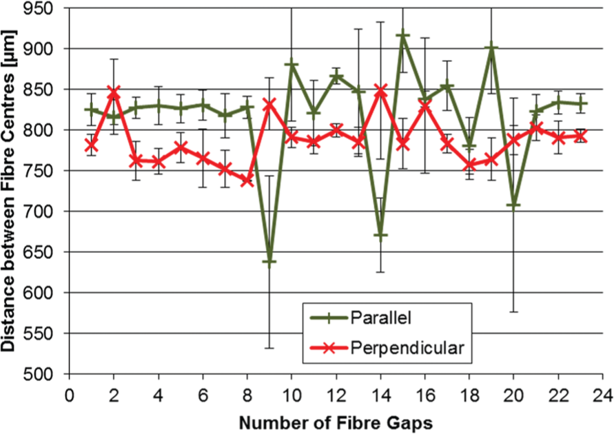
Average distance between fibre cores for both orientations (Trumpf TruFiber; air).
However, opposed to the results for the SPI laser samples, the Trumpf samples, especially parallel fibres, showed a wider range (640–920 μm), whereas perpendicular embedded fibres ranged from 740 to 850 μm. The reason for the greater range for parallel fibres was likely that fibres moved out of the channel due to their propensity to roll and the dynamic forces applied from the sonotrode, which will be discussed later on. Furthermore, as can be seen, for example, for fibres 9 and 10 in Figure 7, as one fibre was displaced from the channel, the distance to the following fibre got shorter which increased the distance to the other adjacent fibre.
Little current knowledge exists about the secure and accurate positioning of fibres during UC. To date, most studies have focused on the plastic behaviour of the material encapsulating the fibres while the fibres were being held in place by clamping mechanisms. Kong 21 found that fibres in close proximity can disturb each other while also impeding the bond formation process during UC. 9 In Figure 8(a), an example of a high quantity of fibres in an Al 3003-H18 matrix without channels is shown. The fibres were not evenly distributed and in some cases in direct contact with each other. The reason for this was that fibres are moving due to the applied oscillations and pressure. Contact of the fibres could present a problem when using delicate fibres such as optical fibres which can easily lose their ability to guide light when breaking. Furthermore, uneven spacing could lead to difficulties when embedding multiple fibre types. In Figure 8(b), SiC fibres embedded in channels after consolidation in this study can be seen. Compared to the fibres in Figure 8(a), the fibres were, due to the channel, restricted in moving and stayed in the channels during consolidation. Furthermore, the fibres were evenly distributed across the matrix interface.
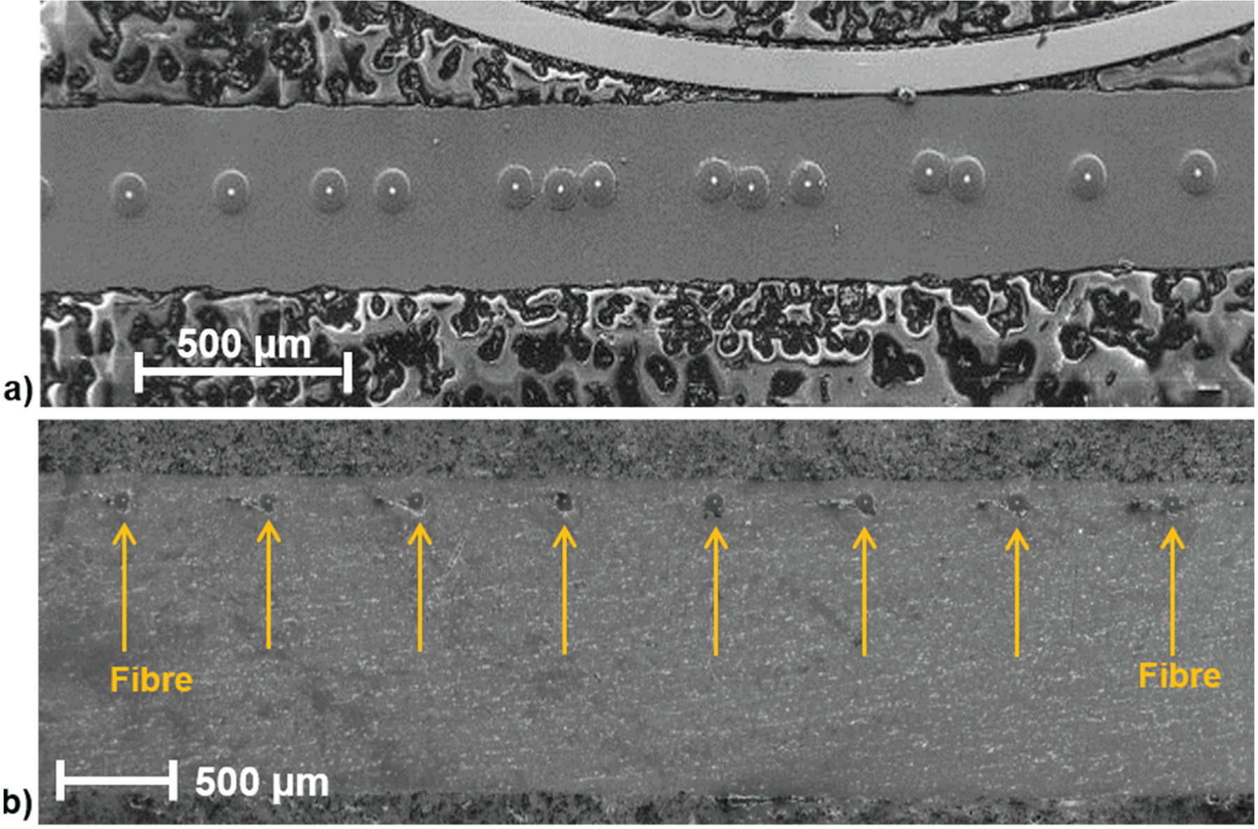
High quantity of SiC fibres within an Al 3003-H18 matrix 21 without channels after UC (a) and with channels (b).
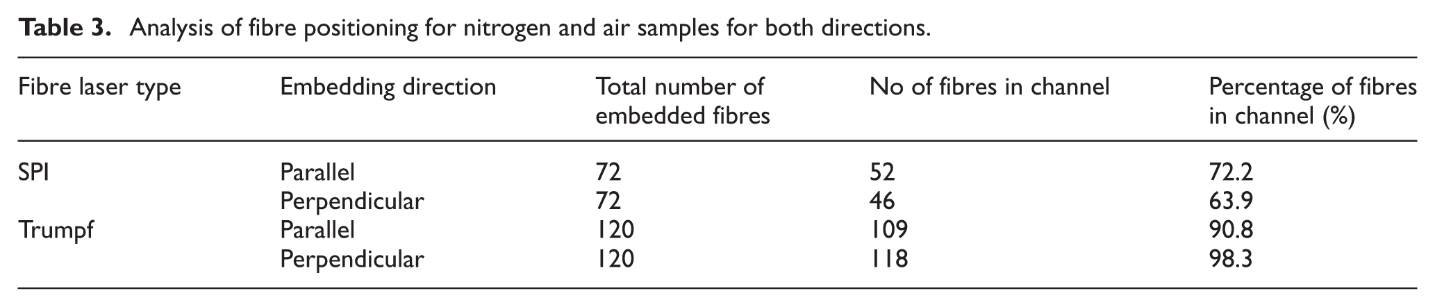
To clarify the aid of the channels for accurate positioning, all fibres were analysed via SEM inspection. The results can be seen in Table 3. The results revealed that fibres in SPI laser samples were less likely to stay in the channels after UC. Only 72% for parallel embedded fibres and 63% for perpendicular embedded fibres were found to be in the channel. The results for Trumpf samples indicated that for both directions over 90% of the fibres remained in the channels after UC, with perpendicular embedded fibres reaching a value of 98%. Hence, only 2 of the 120 fibres moved out of their channel. In Figure 9, an example for fibre movement is presented.
Analysis of fibre positioning for nitrogen and air samples for both directions.
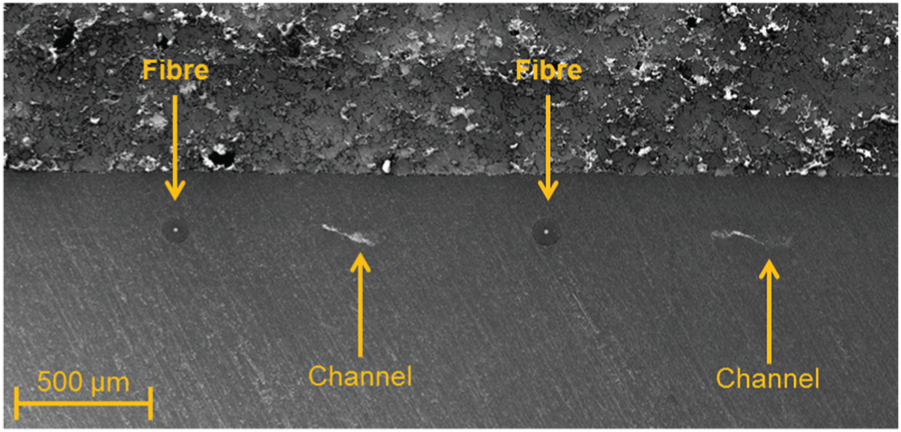
Fibres not embedded in channels after UC.
This behaviour was observed for nearly 30% of the fibres embedded in parallel direction and for nearly 40% of perpendicular embedded fibres for samples processed with the SPI laser. Hence, accurate positioning was difficult to control. The reason for the movement of the fibres for SPI samples during UC was attributed to the lack of sufficient channel depth. Compared to the channels produced with the Trumpf laser which exhibited a channel depth of 65–80 μm, the channel depth for nitrogen samples was only in the range of 40–60 μm. Furthermore, the embedding direction may have influenced the movement of fibres which could explain a difference in movement for both directions for SPI samples. Parallel embedded fibres received the normal force and oscillations from the sonotrode over their whole length during UC, whereas perpendicularly embedded fibres received the normal force and oscillations over their diameter as schematically displayed in Figure 10.
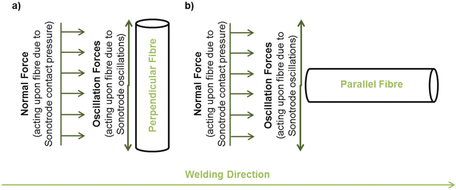
Dynamic forces acting on (a) perpendicular fibre and (b) on parallel fibre with regard to welding direction.
It was suggested that the perpendicular fibres in combination with a smaller depth were, due to the normal applied force, pushed along the welding direction. Furthermore, the rolling direction of the fibres was in favour to move along the welding direction.
On the contrary, Trumpf samples showed that perpendicular embedded fibres gave better results. It was anticipated that due to the deeper channels, the oscillation force was the main influence on fibre movement which made the fibres oscillate around their genuine rolling direction. Hence, depending on a channel existence and the depth, either normal or oscillation force may act on the fibres.
Aid of channels and shoulders for integrity of fibres after UC
Channel and shoulder manufacturing into the metal matrices was intended to meet two conditions: first, the accurate placement of fibres and second, preventing damage of the fibres during UC. To analyse the second condition, all fibres were closely inspected to analyse their integrity after UC.
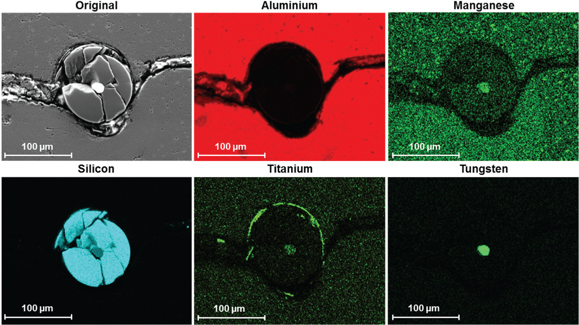
In Figure 11(a) and (b), an intact fibre and a fibre exhibiting cracks are displayed. The degree of cracking varied from sample to sample; however, every sample exhibited at least one cracked fibre. The severity of the cracking varied. Analysis of the cracked fibres and their relation to movement of the fibres was carried out by calculating the percentage of cracked fibres. The results are displayed in Table 4.
Analysis of fibre cracking for all fibres.
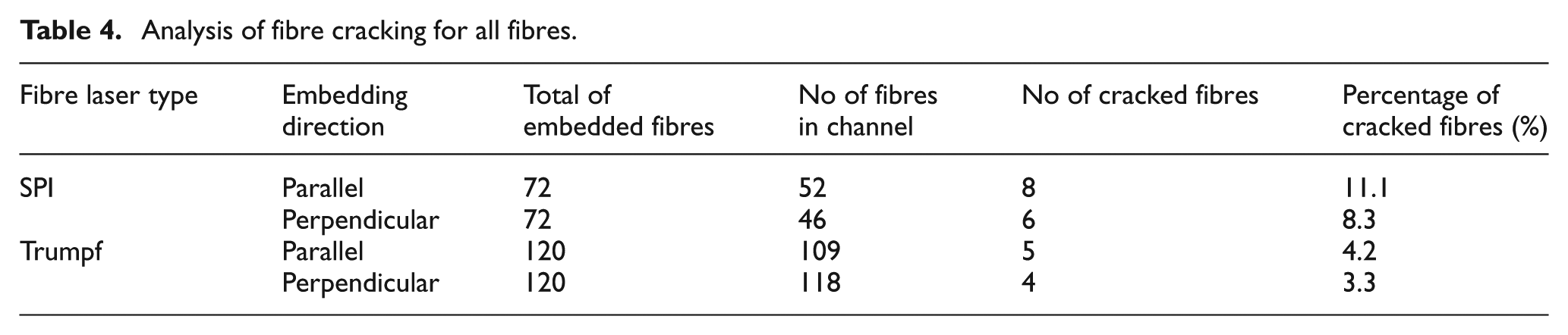
(a) Intact embedded fibre and (b) embedded cracked fibre after UC.
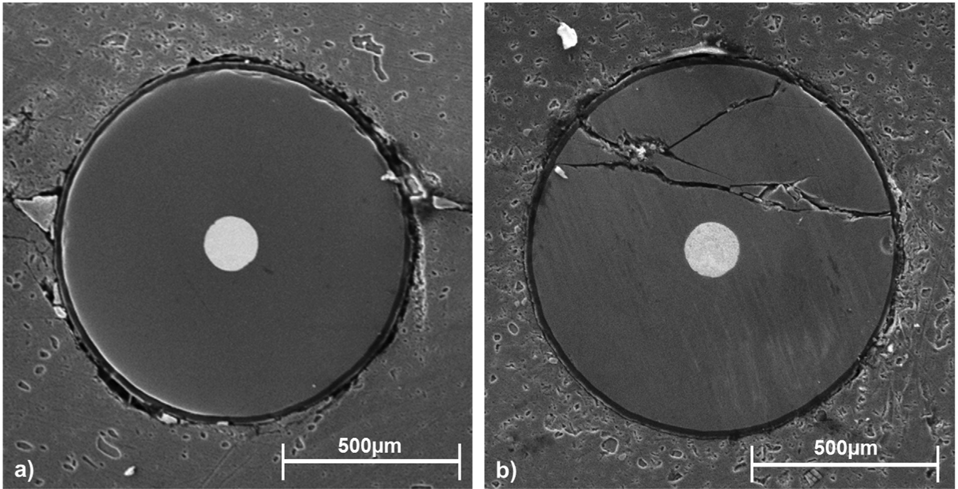
As with the results for fibre movement, Trumpf samples exhibited superior results than SPI samples. The percentage of cracked fibres in parallel direction was 4.2% and 3.3% for perpendicular placed fibres. For parallel embedded SPI samples, the percentage of cracked fibres was over 10% and slightly less in perpendicular direction. It was noted that for both laser types, the percentage of cracked fibres was higher for parallel embedded fibres. A possible reason for cracking in parallel direction may have been the dynamic forces such as normal and oscillating forces acting on the fibre (Figure 10). As discussed earlier, a parallel embedded fibre would experience the forces over the whole fibre length. A perpendicular embedded fibre also receives the forces over the whole length; however, the interaction time is less than for a parallel fibre which may encourage the development of cracks. Another reason for fibre cracking, especially for SPI samples, may have been the correlation between movement of fibres and cracking of fibres. Moving out of the channel increased the force exerted on the fibre by the sonotrode making the fibres more susceptible to cracking due to the applied forces during UC. In Figure 12, a representative EDX map of the main alloying elements in the matrix material and the fibre elements are given.
EDX mapping of elements around broken fibre.
EDX was carried out to understand the distribution of the cracked fibre in relation to the welding direction and welding forces. The results showed that the damaged fibres which stayed in the channel were distributed within the channel rather than along the weld line as can be seen for silicon and titanium. A possible explanation for fibre cracking in the channel may have been a combination of normal force with simultaneous hardening of the channel bottom due to laser processing. Hence, the fibre was exposed to pressure from the top and a hard surface from the bottom which led to fibre cracking via fibre compression. Research on fibre damage during UC has never been reported before for SiC fibres. However, reference samples without channels but containing the same amount of fibre volume also showed fibre damage. This was suggested to be another indication for damage occurring due to the dynamic forces imposed during UC. Further research on fibre breakage is currently being investigated to clarify which major factors are causing the damage.
Conclusion
This study demonstrated a novel and unique approach to advance UC as a manufacturing process for high volume fibre integration. Compelling evidence for the aid of the laser manufactured channels to accurately position high volume fractions of fibres was observed for samples which exhibited an increased channel depth (Trumpf) as opposed to less deep channels (SPI). Over 90% of the parallel embedded fibres (9.2 vol%) manufactured with the Trumpf laser were observed to remain in the channel, after UC. For perpendicular placed fibres, 98% (10 vol%) of the fibres remained in the channel. Only 63.9% for perpendicular placed fibres in SPI manufactured samples and 73% for parallel placed fibres stayed in the channel, which was concluded to be due to the smaller channel depths. Hence, laser-processed channels can enhance the accurate distribution of fibres within a MMC which aids the further development of the UC process as a MMC manufacturing process.
The study of the preservation of fibre integrity after UC showed that every sample exhibited fibre damage. Up to 11% of the fibres embedded in SPI samples were damaged and up to 4% of the fibres embedded in Trumpf samples were damaged which may be attributed to the different channel depths. Furthermore, fibres embedded parallel to the welding direction were more readily damaged than fibres in perpendicular direction. It was suggested that dynamic forces over the whole fibre length (parallel) caused more fibre damage due to the longer exposure time during UC. Additionally, it was suggested that the microstructure of the channel surface may have had an influence on fibre breakage. Further investigations to identify the catalyst for fibre damage will be carried out. The influence of the embedding direction on fibre damage has been investigated for the first time and contributes to the further understanding of the dynamic forces induced on delicate materials with regard to future embedding research and application.
Footnotes
Declaration of conflicting interests
The author(s) declared no potential conflicts of interest with respect to the research, authorship, and/or publication of this article.
Funding
The author(s) disclosed receipt of the following financial support for the research, authorship, and/or publication of this article: The authors gratefully acknowledge the financial support of the EPSRC/IMCRC through grant number EPSRC IMCRC 275.