
Abstract
In order to break through the limitation of traditional axisymmetric spinning, a discretization method is made to form an oblique cone by die-less shear spinning technique. Due to the characteristics of asymmetric spinning, the roller feed should harmonize with the spindle rotation, and the roller path is derived through a discretization method. The thickness variation of oblique cone in different directions is coincident with the sine relation in axisymmetric shear spinning. The surface quality, especially the surface smoothness (the distribution of arrises) and surface roughness of the spun part, is discussed by analyzing the roller motion and important spinning parameters, and a smaller axial feed rate f and a smaller angle increment Δα can improve the surface quality.
Introduction
Generally, metal spinning refers to a kind of plastic forming process that allows production of hollow axisymmetric sheet or tube workpiece as described by Music et al. 1 According to the variation degree of wall thickness, spinning is classified into two processes: shear spinning and conventional spinning. As a forming process, comparing with other techniques, such as stamping and deep drawing, spinning exhibits its advantages of low-cost, high quality and small load as pointed out by Shimizu. 2
Conventional spinning is a developed process, no matter the process or the mechanism. Wang et al. 3 researched the effects of the roller feed ratio on wrinkling failure in conventional spinning of a cylindrical cup. Essa and Hartley 4 optimized conventional spinning process parameters by means of numerical simulation and statistical analysis. However, conventional spinning is limited to producing axisymmetric shapes.
In order to break through the limitation of traditional axisymmetric spinning, in the recent 30 years, the researchers from all over the world make contribution to carry out asymmetric spinning. Amano and Tamura 5 and Gao et al. 6 were probably the first who succeeded to form the asymmetric elliptical cone spinning by means of a spinning machine equipped with the combined mechanism of cams and links, which enabled the roller to follow the elliptical mandrel profile by oscillating radially. Arai 7 developed a hybrid force control system to drive the roller to track the mandrel of spun part with quadrilateral cross section. In a trial of asymmetric spinning performed by Awiszus and Meyer, 8 a standard spinning lathe with spring-controlled rollers was applied to form spun parts with triangular cross section. Especially, Xia et al. 9 proposed an advanced method based on die-driven to produce polygonal cross-sectional workpiece, as shown in Figure 1. However, the adaptability of the method is basically limited to die shape, and the cost of die manufacturing is high. In the previous study, an offset tube was carried out by Kuang et al. 10 and Xia et al. 11 as shown in Figure 2. The construction of the offset tube is similar with the oblique cone in this study, but tube spinning used in asymmetric forming has its limitation in blank shape.
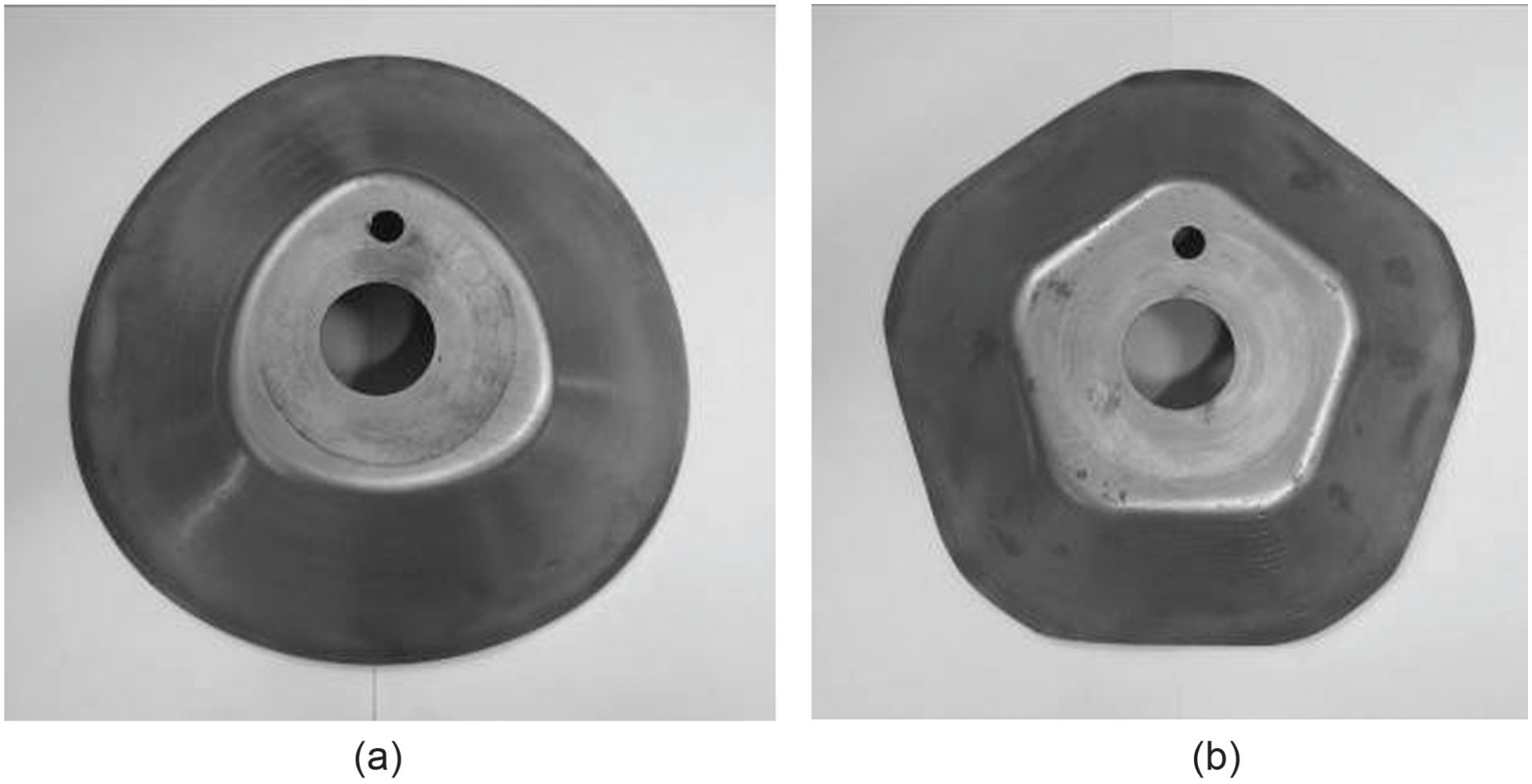
Spun workpieces with polygonal cross section.
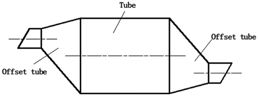
Schematic diagram of offset tube spinning.
Metal spinning technique, either machining equipment or product shape, has achieved great progress. Sekiguchi and Arai 12 and Xia et al. 13 developed a spinning method, which can be used to produce curved shapes and non-axisymmetrical shapes without using a die. For the position of the roller and the angle of the spindle should be controlled synchronously, a series of curved tube shapes were formed. This article aims at the die-less shear spinning process of oblique cone. During the experimental process, the technological possibility of the die-less shear spinning of oblique cone is confirmed. In die-less shear spinning, the blank formed is supported at the end of a cylindrical mandrel that rotates around a main spindle as described by Wong et al. 14 In this process, there is no need to use a die that has an identical outer shape with the inner shape of the workpiece to be formed as shown in Figure 3. In the latest study of Sekiguchi and Arai, 15 a flexible method of forming circumferentially variant wall thickness distributions on the same shape is used in synchronous die-less spinning and force-controlled shear spinning.
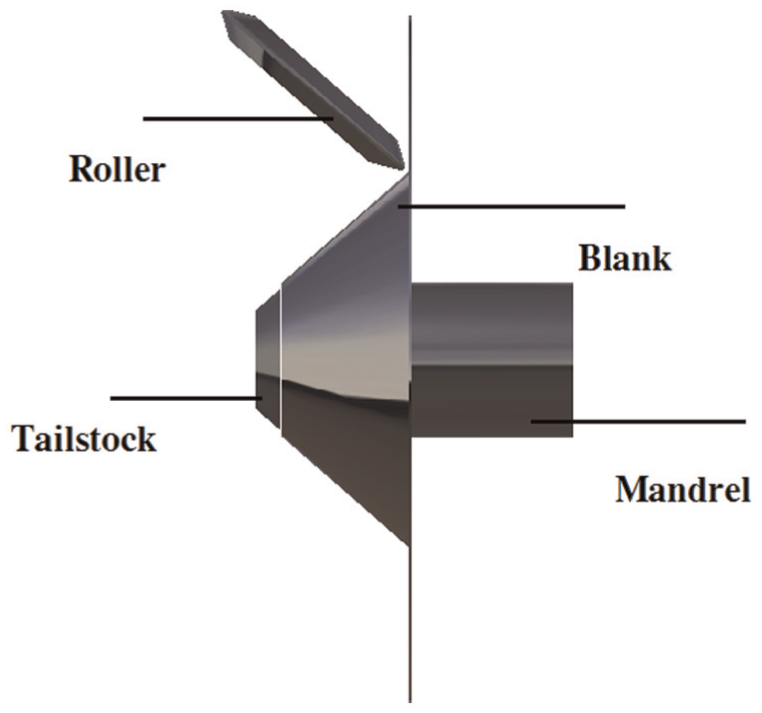
Schematic of die-less shear spinning.
Scanning the literature, research about oblique cone shear spinning is rare, and the method of how to form an oblique cone by spinning process is almost a blank. In this article, in order to generate an expected contour, the author designs a roller path and gets the expression of roller position in workpiece coordinate system. The reason why the arises generate around the spun workpiece and its distribution regularities is analyzed. Additionally, the surface quality, especially the surface smoothness and surface roughness, is discussed by researching the roller motion and important spinning parameters.
NC spinning machine
Figure 4(a) shows a numerical control (NC) spinning machine (PS-CNCSXY600-5) that is used in present investigation. The spindle is driven by servomotor (GS3050Y-NP2), four sophisticated servomotors are fixed along axial and radial directions of two roller motion in both sides of the spindle, and these control accuracy is 0.001 mm. In order to reduce the position error caused by velocity variation of the roller, synchronous control system is adopted. The spinning path is controlled by the combination of mandrel rotation and roller feed rate. In each defined angle increment Δα, the roller moves to a predetermined position with the spindle rotating a certain angle.
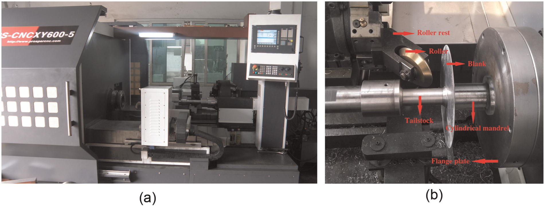
PS-CNCSXY600-5 NC spinning machine: (a) full view of machine and (b) working portion of spinning.
In Figure 4(b), the working portion of spinning is shown. In oblique cone spinning, only one roller is used and driven by two sophisticated servomotors in the same side. The blank is held in the center by mandrel and tailstock, and the cylindrical mandrel is rotated with the spindle by the connection of flange plate.
Experiment
Analysis of workpiece and mandrel
A three-dimensional (3D) model of oblique cone is shown in Figure 5. Some illustrations about the cone are described as follows:
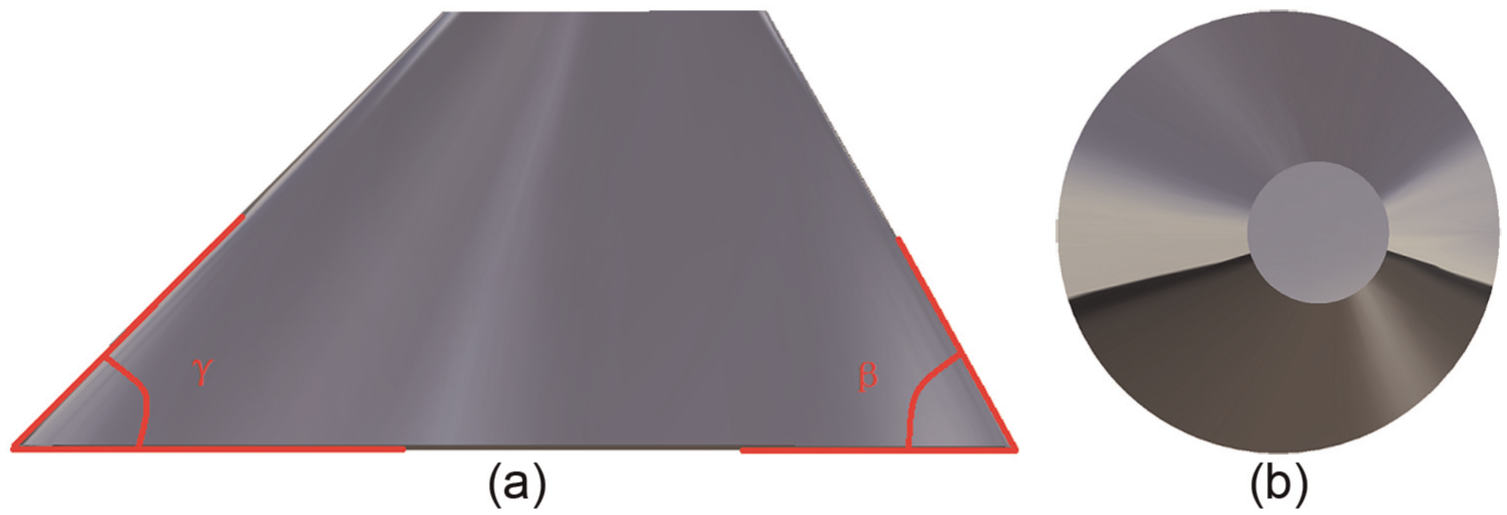
Three-dimensional model of oblique cone.
The maximum of slope angle β should be different from the minimum one γ. A standard circular cone can be formed by conventional method.
Arbitrary cross section of the oblique cone is a circle.
The oblique cone workpiece is widely used in aerospace field. Due to its asymmetrical characteristic, the contour cannot be generated by a generatrix rotating with an axis; therefore, most plastic forming processes are difficult to produce such workpiece. The asymmetric shear spinning process is proved appropriate for this workpiece.
In asymmetric spinning test, the technique of die-less spinning has been used. In order to support the blank, a cylindrical mandrel is necessary, which is connected with the main spindle of machine. More importantly, the size and shape of the mandrel cross section should match with the counterparts of workpiece top.
Roller path
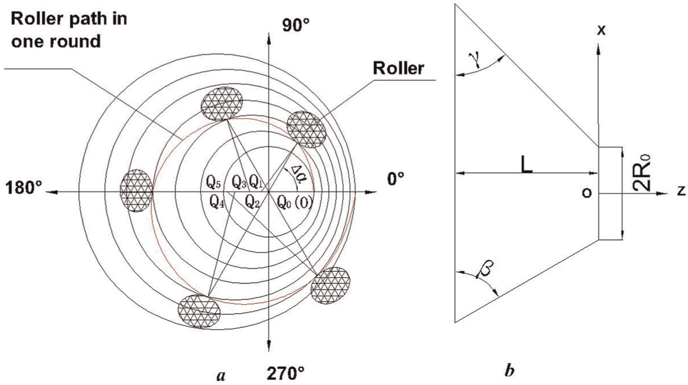
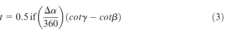
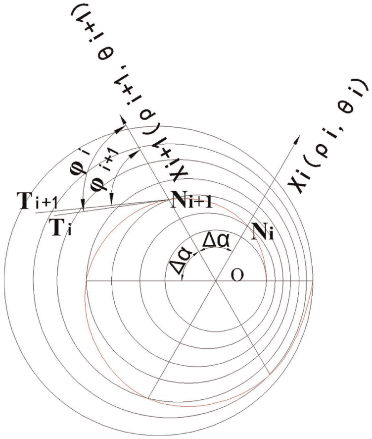
Figure 6 shows the schematic of spinning path. The circle O is the cross section of the mandrel, and the main spindle rotates around the axis OZ. The spinning path is a trace of discrete spiral line to form the product expected, and it is controlled by the combination of mandrel rotation rate and roller feed. To simplify derivation, the first effective round of the mandrel is analyzed as shown in Figure 6(a). The workpiece coordinate system is defined with respect to the cylindrical mandrel: the center point O is the origin, X-axis coincides with the radial direction of roller feed and Z-axis coincides with the axis direction. In the radial direction of roller motion, by the cosine law, the X-coordinate (x) of roller on workpiece coordinate system is expressed as
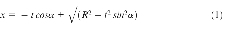
where α (°) is the rotation angle of mandrel, R is the radius of arbitrary spun cross section varied with α, and t is the distance between the center point
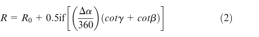
where R0 is the radius of cross section of the mandrel; β and γ are the maximum and minimum of slope angle as shown in Figure 6(b), respectively; Δα (°) is a linear increment of α; f is the axial feed rate of system; and i is a global variable and it increases to 1 whenever the spindle rotates an angle increment Δα. So,
Schematic of the spinning path.
Similarly
The theoretical path designed to form the oblique cone is an offset spiral. However, because of the roller motion restricted by the working principle of machine-tool, the theoretical spinning path cannot be generated accurately. Therefore, a discretization method is used to substitute the impossibility. Naturally, the increment Δα plays an important role in measuring the dispersion degree. A smaller Δα can improve the precision of the spinning path furthest, but it demands a high technical requirement to feed system and reduces the working efficiency, so it is necessary to choose an appropriate Δα according to NC machine accuracy and the requirement for the shape precision of spun workpiece.
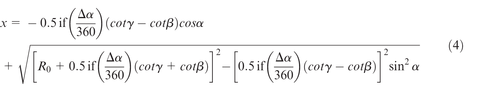
In conclusion, substituting equations (2) and (3) into equation (1), ultimate expression of x is expressed as
In axial direction of roller feed, due to the axial feed rate of synchronous system is a constant f, the Z-coordinate (z) on workpiece coordinate system is expressed as
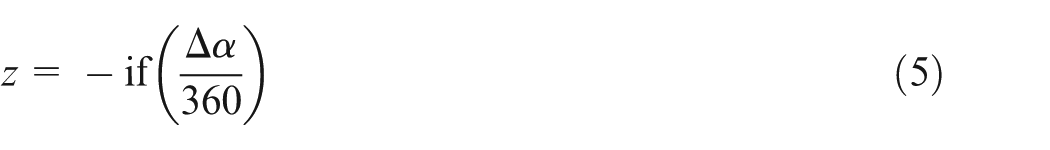
In each interval Δα, the spinning path is controlled by the combination of spindle rotation and roller feed in axial and radial directions.
Spinning experiment
In order to confirm the applicability of the discretization method, a series of trials were performed to form different kinds of oblique cones. Table 1 shows the key parameters in one spinning trial.
Key parameters for the spinning process.
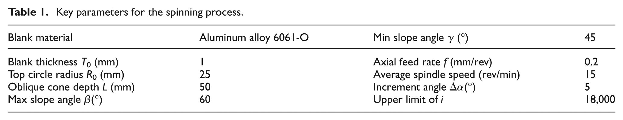
Inserting the parameters above into equations (4) and (5), the curve of X and Z are drawn in Figure 7, and the abscissa i represents the node number on discrete spiral. It starts from 0 and ends with upper limit (18,000). Figure 8 shows the die-less spinning product with oblique cone shape.
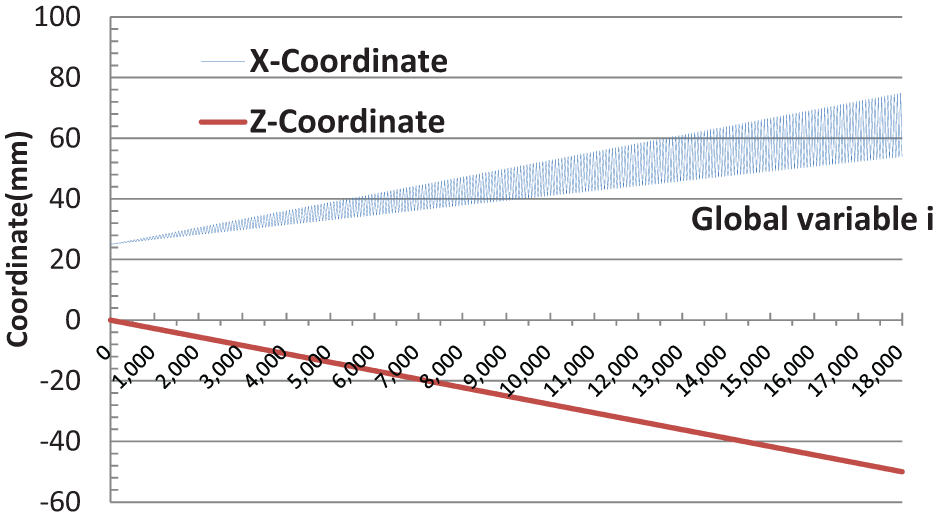
The curve of X-coordinate and Z-coordinate.
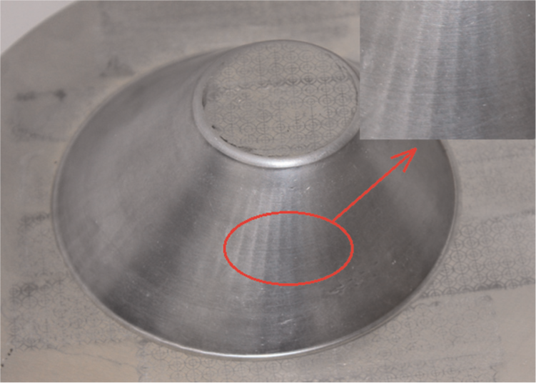
The die-less spinning product with oblique cone shape.
Discussion
Thickness distribution
An oblique cone whose maximum and minimum slope angles are 60°and 45° was successfully formed by discretization method. Measuring the slope angles after deformation, we found that the maximum and minimum slope angles were very precise—60° and 45°, respectively. It indicates that the roller path derived and discretization method used can meet the shape requirement of oblique cone shear spinning. In axisymmetric shear spinning, the final wall thickness T of conical product is determined by the half cone angle θ and the original thickness T0 of blank according to the sine law as described by Sekiguchi and Arai:
15
In order to achieve the relationship between final wall thickness and original thickness in asymmetric spinning, the thickness of the oblique cone is measured by a gauge (GE-DM5E). The measuring points and their thickness in eight directions are shown in Figure 9, and the half cone angles θ in respective directions are obtained geometrically. Comparing with the theoretical thickness according to sine law in axisymmetric spinning, Figure 10 shows the relative error to theory thickness
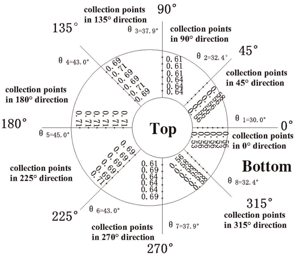
The distribution of thickness measuring points and their thickness (mm).
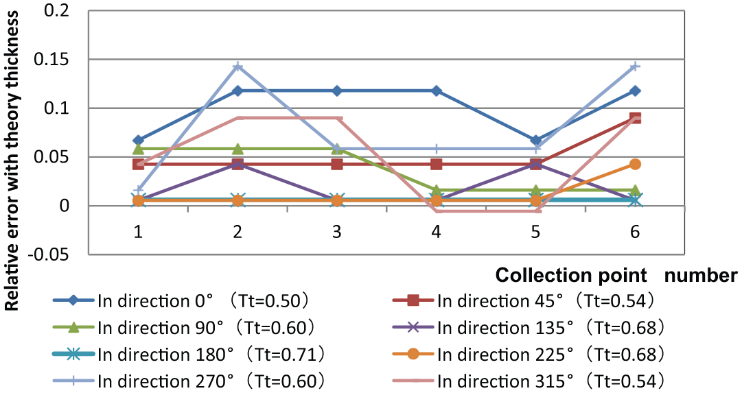
Relative error to theory thickness
In Figure 10, the relative errors of most collection points to respective theory thickness are around 0.04. But there is another six points that their relative errors to theory thickness are more than 0.1. Because of the curved feature of the workpiece and the distribution of arrises around the side surface, it is easy to cause measurement error. Therefore, it is reasonably certain that the thickness variation in different directions is coincident with theory thickness, that is, thickness along different directions meets the sine relation in axisymmetric shear spinning. Comparing with the elliptical cone spinning with a die as described by Shimizu, 2 the thickness of conventional spinning or asymmetric spinning with a mandrel can be controlled by setting the clearance between the roller and mandrel, though die-less shear spinning is flexible and low-cost, the wall thickness is non-uniform.
Surface quality
As shown in Figure 8, a series of arrises distribute observably around the spun workpiece. According to the analysis in section “Roller path”, though the whole offset spiral is dispersed, in each increment interval Δα, the projection of spinning path in top plane of oblique cone is a segment of Archimedes spiral. In Figure 11, two polar coordinate systems
Schematic of the spinning arris.
In Figure 8, along different directions, the visibility of the arrises is not the same. The arrises on both sides of the 0° and 180° directions are not observable and the surface is smooth compared with the counterparts in other directions. According to the analytic geometry relationship, the trend of increment (
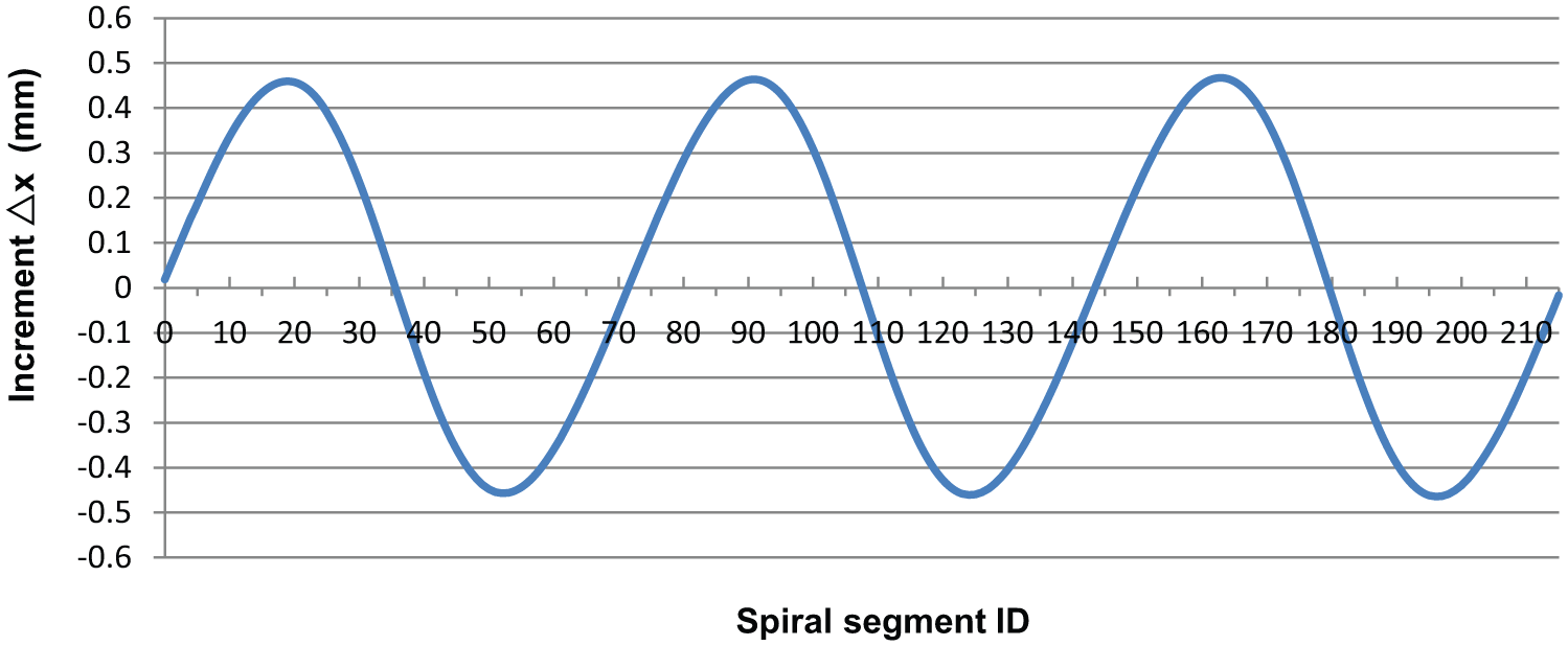
The curves of Δx in round 124–126.
In Figure 12, all of the maximum and minimum points are located on spiral segment ID = 19,52,91,124,163,196 almost corresponding to 90° and 270° directions; similarly, the zero point, such as spiral segment ID = 0,36,71,108,143,180 and 215 almost corresponds to 0° and 180° directions. Therefore, it proves that a big increment
As the cone is formed based on equations (4) and (5), the surface smoothness is influenced by the angle increment Δα significantly. To improve the surface smoothness, a smaller Δα is adopted in oblique cone forming. However, a smaller Δα puts forward higher requirements for NC spinning machine. For example, if Δα = 1°, f = 0.2 mm/rev, although the surface quality gets more improvement in theory, it needs the roller feed 0.00056 mm in axial direction while the spindle motor rotates 1°. Most of the NC machine cannot achieve such accuracy. Therefore, a group of Δα and f should be harmonized to improve the surface quality and be beneficial to reduce the cost of NC machine.
Figure 13 shows an oblique cone with the spinning parameters Δα = 2°, f = 0.4 mm/rev. Comparing with the first one (Δα = 5°, f = 0.2 mm/rev), the arrises are inconspicuous and the surface smoothness is improved significantly.
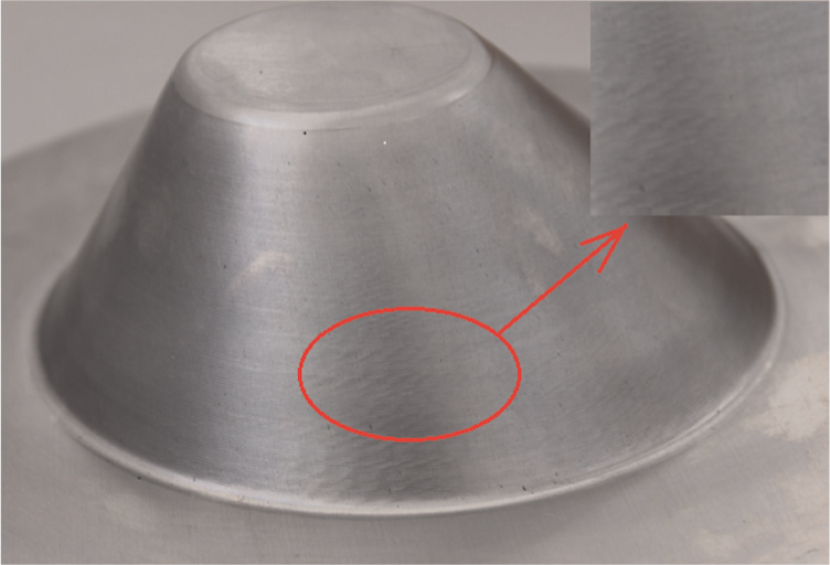
Oblique cone with improved surface smoothness.
Although the smoothness of circumferential surface has been improved, the surface quality along radial direction of the second spun workpiece is decreased. As shown in Figure 14, the scan length of the measurement is 4000 μm, the scan speed is 50 μm/s and the measuring direction is perpendicular to surface lay. Based on the measured parameters above, surface roughness Ra (arithmetical mean deviation of the profile) of the two parts is 0.7975 and 0.9026 μm. It proves that a small f can improve the surface roughness of the spun part.
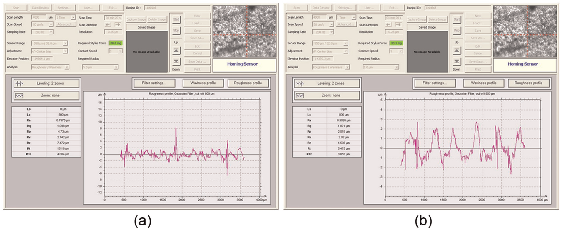
Surface roughness of spun workpiece: (a) spinning parameter with Δα = 5°, f = 0.2 mm/rev and (b) spinning parameter with Δα = 2°, f = 0.4 mm/rev.
Conclusion
A series of oblique cones were formed by die-less shear spinning on the NC spinning machine. The conclusions obtained through the forming process are summarized as follows:
The discretization method has been used to generate the spinning path for the forming of oblique cone. The shape size is reliable compared with design.
The trend of final wall thickness of oblique cone is almost consistent with the theoretical thickness calculated by sine law in axisymmetric spinning, that is, the wall thickness is non-uniform. It affects product performance, especially under a bad working condition.
In each increment interval Δα, the projection of spinning path in top plane is a segment of Archimedes spiral. The reason why a series of arrises generate around the spun part is the existence of non-differentiable point between any two adjacent spirals.
The surface smoothness is fine on both sides of the 0° and 180° directions, but the counterpart in other directions is rough relatively. To improve surface smoothness, it is appropriate to adopt a small Δα; the surface roughness of spun workpiece is determined by axial feed rate f, and a small f can make the surface finish fine. The value of f and Δα should be chosen reasonably according to the machine precision and the requirement of surface quality.
Footnotes
Declaration of conflicting interests
The author(s) declared no potential conflicts of interest with respect to the research, authorship, and/or publication of this article.
Funding
The author(s) received no financial support for the research, authorship, and/or publication of this article.