
Abstract
The process capability of die-less hydroforming for producing tubular structures of complex geometries was investigated. Multi-lobe tubular structures were chosen for this study as they are capable of carrying higher loads than normal tubes of the same weight. The forming characteristics of three variants of tubular geometry with longitudinal lobes, circumferential lobes, and helical lobes were studied through numerical analysis. The parameters that were investigated were tube wall thickness, tube diameter, tube length-to-diameter ratio, pressure loading paths, and lobe-forming patterns. The finite element analysis showed that the length of the tube does not influence the lobe formation for all three tube variants. The finite element analysis results also demonstrated that lobe wall thinning varies linearly with hydroforming pressure for all multi-lobe tube patterns studied. The strength-to-weight benefit of the tubular structures was also verified through finite element analysis for annealed stainless steel tube sample of 200 mm length, 40 mm diameter, and 2 mm wall thickness. The longitudinal lobed geometry, circumferential lobed geometry, and the helical lobed geometry all were able to carry significantly larger loads as compared to a blank tube of the same mass under compressive, flexural, and torsional loading conditions. To test the viability of the die-less hydroforming process, a longitudinal lobed tubular structure was fabricated and formed. The results from this study indicate that a die-less hydroforming manufacturing process is viable and capable of producing strong, lightweight parts of complex geometries. Besides being capable of producing complex tubular structures, the costs associated with die-less hydroforming are significantly lower due to the absence of a press and dies. However, preparation of tubular blanks requires reliable weld seams and rolling operations.
Introduction
The use of hydroforming manufacturing processes has rapidly increased over the past decade due to increased research and technological advances. One of the main benefits of this process is that the initial material is fully utilized so that thinner gage metals can be used while maintaining the necessary strength requirements. Currently, there are two primary fluid-assisted metal-forming techniques: tube hydroforming (THF) and sheet hydroforming (SHF). THF is the process of conforming a tube to a die in order to create a desired shape through the use of internal and axial pressure. The tube is generally designed to fit a particular die, which acts as a forming tool during the hydroforming process. A hydraulic press is used to encase and clamp the tube between the two dies during forming. Hydraulically powered cylinders are inserted into the open sides of the tube and provide a compressive axial force while supplying an internal pressure via fluid. SHF focuses on the forming of either a single-blank or double-blank sheet through the use of a fluid medium. The fluid medium can either directly form the blank, known as active hydroforming, or provide a counter-pressure to assist in forming in a process known as passive forming. Due to the architecture of SHF, more complex geometries can be formed. However, in SHF, the press needs to have enough pressure not only to deform the material but also to overcome the counter-pressure exerted by the fluid.
Hydroformed parts can be found in automobiles, aircrafts, motorcycles, bicycles, and household parts such as fittings. In the automotive industry, applications of hydroformed parts include the following: (a) manifolds, catalytic converters, tail pipes, and other parts pertaining to the exhaust system; (b) engine cradles, drive shafts, and cross members; (c) chassis frames and rear axle parts; and (d) interior parts such as instrument panels, seat frames, and pillars.1–3 Parts manufactured via the hydroforming process exhibit certain characteristics that make them extremely valuable to automotive applications; most notable among these benefits are as follows: (a) reduction of weight by selectively thinning the tube walls, (b) increase in strength and stiffness, (c) significant decrease in secondary operations, (d) dimensional accuracy, and (e) efficient use of materials and consolidation of parts used. 4
Although there are an increasing amount of components produced via hydroforming, there are several limitations preventing the growth of the technology. Chief among these are (a) cost of presses and tooling, (b) press capacity, (c) process cycle time, and (d) ability to produce a large spectrum of complex geometries. Equipment cost for a hydroforming setup which includes presses, punches, dies, hydraulic, and pressure system can often be much more expensive than that of a traditional metal-forming operation. The most obvious limitation of THF is the inability to create any shape other than hollow round or box parts without other operations. Complexity of the parts made is limited not only by the tube geometry but also by the capacity of the press and the required calibration pressure. Tight corners and small die radii require a very high calibration pressure which increases the load on the press. Thus, the equipment involved in THF can become extremely expensive depending on the complexity and size of the part, that is, there is a threshold part size beyond which conventional hydroforming process will no longer be economical.
There are families of products or structures with certain characteristic which could be hydroformed without the use of dies or presses. For example, in the construction industry, large shell structures such as columns which support roadways, silos that hold gas or other commodities, or tubular support members for bridges; some of these structures could be produced to be lighter and stronger through die-less hydroforming. The elimination of presses and dies allows for small or very large structures to be candidates for die-less hydroforming. Few studies on making large spherical vessels by fluid pressurization without the use of dies have been reported.5–7 Recently, studies on the use of die-less hydroforming process for tube joining have been reported.8,9 The major goal of this study is therefore to explore potential geometries that are ideal for die-less hydroforming process. This process has the potential to produce complex structures that could not be possible to produce by any other forming operations.
Objectives and approach
The objectives of this research are (a) to explore fields of application for die-less hydroformed components beyond the current hydroforming applications such as automotive, aerospace, and household appliances; (b) to establish major forming variables that have significant influence on die-less hydroforming; and (c) to design an experimental setup and conduct experiments to demonstrate the viability of a die-less hydroforming process.
To meet these objectives, finite element analysis (FEA) is used as a tool to explore complex geometries that can be produced through die-less hydroforming. Several classes of geometries are first developed and analyzed using FEA to determine their feasibility of production and benefit to the market, as discussed in section “Process capabilities of die-less hydroforming.” In section “Parametric study of die-less hydroforming of multi-lobe tubular structures,” one classification of parts is then extensively studied using FEA in order to determine geometry variation and forming characteristics. To demonstrate the viability of the process, die-less hydroforming experiments are carried out. The preliminary experimental results are discussed in section “Experimental trials,” followed by section “Conclusion.”
Process capabilities of die-less hydroforming
The concept behind die-less hydroforming is to attach multiple blanks together by welding or through a series of welds and introducing fluid pressure between the welds. The initial step in the die-less hydroforming process is to cut the sheet blanks into an initial geometry which is determined by the desired final form. Two matching blanks are then welded in some fashion so that the area between the welds is completely sealed. One or several holes are created on one sheet blank where the fluid will be introduced between the welds, allowing the material to form freely. Through this process, the two primary variables that can be manipulated in order to create different geometries are initial blank shape and pattern of the weld.
Die-less hydroforming holds several advantages over traditional THF and SHF, including the ability to create complex geometries that cannot be produced by current hydroforming processes, elimination of dies and press thereby drastically reducing cost, and beginning of undeformed part as any geometry, not limited to a tubular shape or sheet blank. This freedom of geometry allows for the die-less process to create custom, complex geometries that could not possibly be formed by other metal-forming processes. In many forming operations, dies experience significant wear due to frictional effects which hinder formation and require either reworking of the dies or replacement. Significant amounts of time and resources have to be dedicated to die development to reduce wear and frictional effects during forming. Therefore, the benefits of a die-less process are not only formation of the part but also reduction of cost plus research and development time.
In order to develop a die-less hydroforming process that is most beneficial to the metal-forming industry, several objectives must be met such as (a) versatile process that can create a number of different complex geometries, (b) opportunity for large volume production with low cycle times, (c) potential to hydroform large structures that are not feasible with conventional hydroforming, and (d) minimum scrap, that is, full utilization of material. The development of this process begins with a classification of geometries that can be produced through die-less hydroforming based on their formed shape. One of the primary benefits of a die-less hydroforming process is the ability to create complex geometries that are not possible through other methods. In this study, potential geometries were explored and classified into three families based on their shape and application. Each of these geometries has several real-life applications and can be formed through die-less hydroforming. The geometries that were studied include circular ring shapes, shell structure, and arch structural families. Finite element (FE) simulations for die-less hydroforming were conducted for these families. Formed shapes from FE models for circular shape with four spokes, helical lobed shell structures, chassis cross member, and bridge arch are shown in Figures 1(a), 2(c), 3(b), and 4(a), respectively. For all the simulations, stress–strain data for stainless steel 304 were used. The simulations were carried out in Abaqus/explicit solver. More details on the simulations are given in section “Parametric study of die-less hydroforming of multi-lobe tubular structures.”
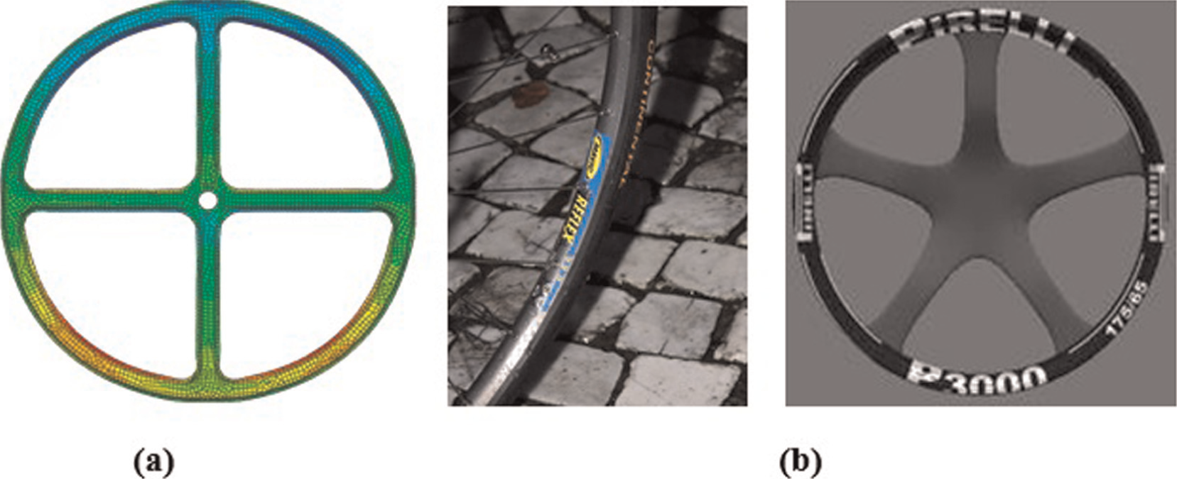
(a) Formed geometry under vertical loading and (b) application examples.
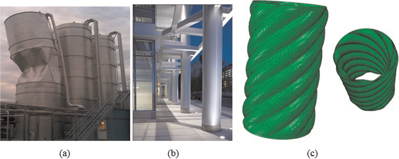
Potential applications of Die-less hydroforming. (a) Silo structures, (b) Steel columns and (c) Hydroformed structure.
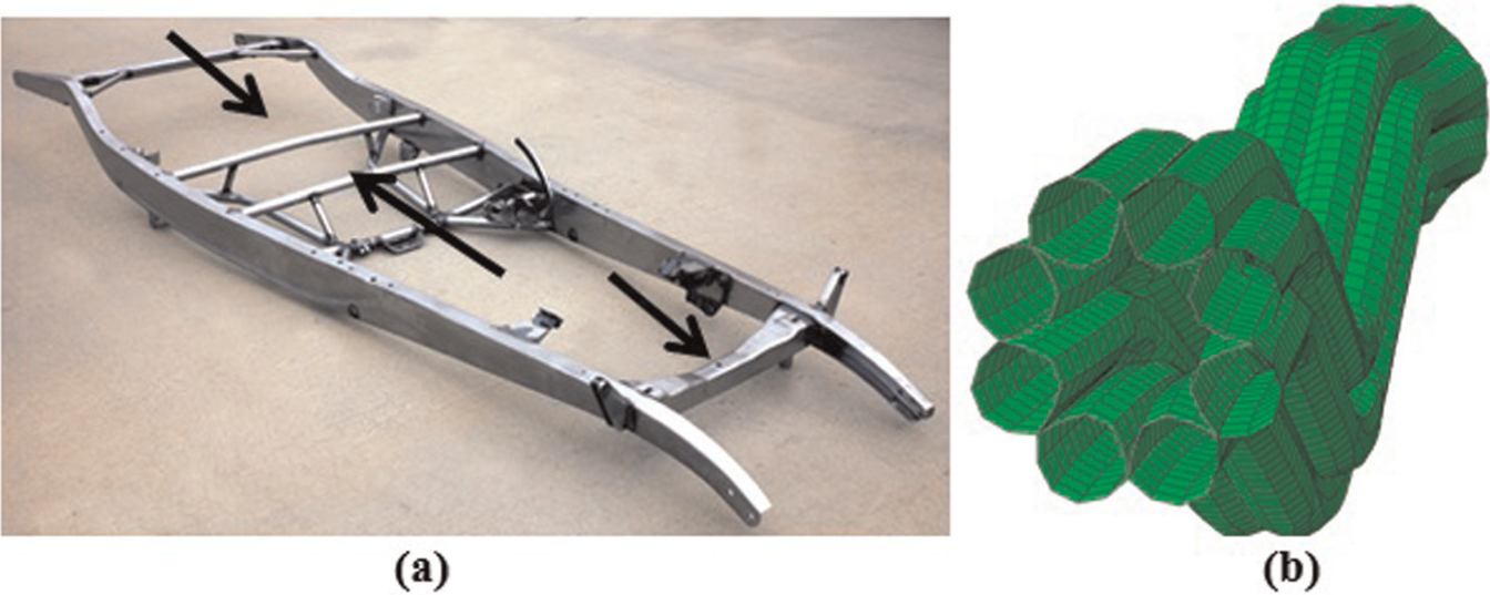
(a) Chassis for a typical automobile and (b) cross-sectional view of a die-less hydroformed chassis cross member.
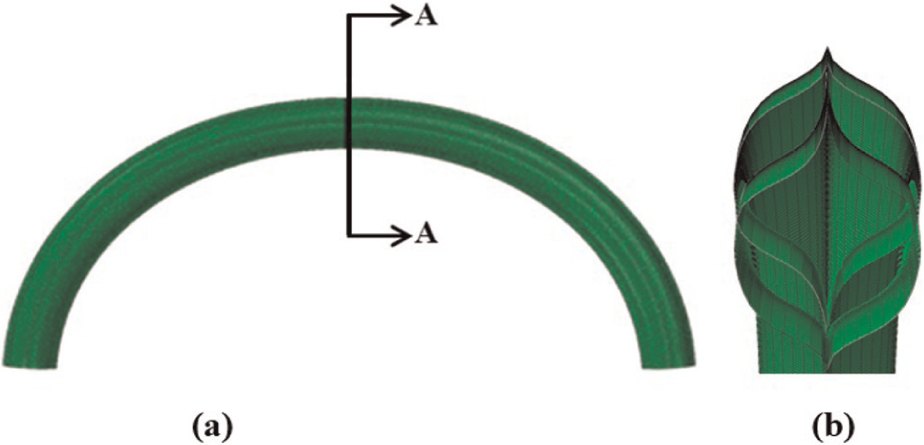
(a) FEA model of an arch created by die-less hydroforming and (b) view of cross section A-A.
Circular ring shape family
This family is characterized by circular shapes like that of a steering wheel. Figure 1(a) shows a die-less hydroformed wheel subjected under vertical loading. This shape could be utilized in several real-world applications that involve circular structures, such as pulleys or cams. An obvious application of this family of geometries is rims for cars or bike tires (Figure 1(b)). Most alloy rims are produced through computer numerical control (CNC) machining which can be time-consuming and wasteful of material. Through a die-less hydroforming process, different rim shapes can be made without the use of expensive CNC or water jet machines. Another benefit to using hydroforming is the work hardening experienced by the geometry. Besides increasing the second moment of inertia via hydroforming, the strength of the structure will also increase due to work hardening.
Tubular/shell structure family
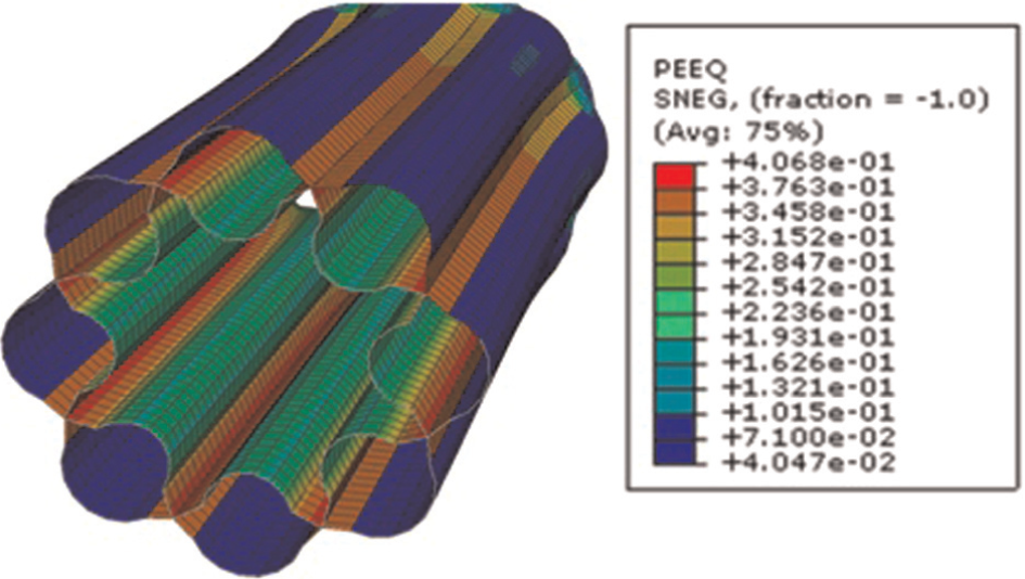
The tubular/shell structure family is characterized by tubular or shell structures that feature several different welding configurations for different uses. During hydroforming, these structures are work-hardened, resulting in higher strength. Thin-walled shells with inflated lobes via die-less hydroforming can replace much thicker tubes of the same material. Figure 2(a) and (b) shows some possible applications for the tubular structures in geometry that belongs to shell structure family. Large steel columns are often used in the construction industry for supporting roadways, bridges, and buildings (Figure 2(b)). These columns are usually used as a base for concrete that surrounds the outer and inner walls of the tube. Large shell structures like the silo pictured in Figure 2(a) typically need to be supported along the internal wall to prevent buckling. Similar structure could be made through die-less hydroforming, which would not require additional support. Figure 2(c) shows a FE simulation model of a die-less hydroformed complex tubular structure with six helical lobes that were carried out by the authors to explore various shell structures that can be hydroformed. Through the die-less hydroforming technique, all of these structures can be produced easily while reducing the weight and increasing strength. Also, the unique look to die-less hydroformed tubes could be desired by architects.
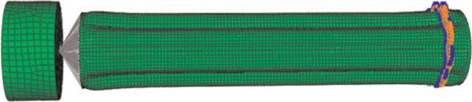
There are also several potential applications for these geometries in the automotive industry. Tubular structures are often used in automobile structure to reduce weight and still be capable to provide sufficient structural rigidity against various modes of mechanical loading. Figure 3 shows a potential application of a die-less hydroformed tubular structures in a chassis. Hollow chassis cross members are used to provide rigidity between the chassis box frame. The use of the die-less hydroformed tubes will reduce weight since thin-walled tubular materials could be used while maintaining the strength required for even heavy utility trucks. Figure 3(b) shows a FE simulation model of die-less hydroformed cross member carried out by the authors.
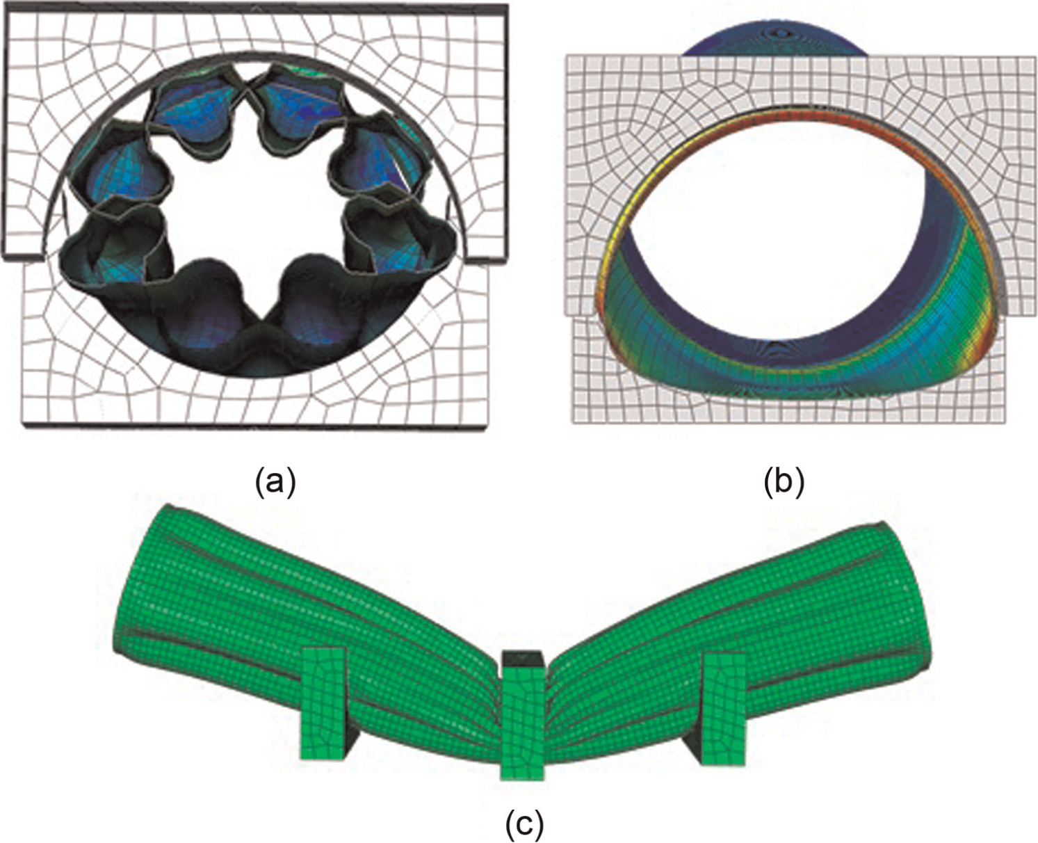
Arch structural family
Arch structures are widely found in the construction industry. They are used in numerous structures because of their ability to bear load and for aesthetic purposes. Arches of different configurations can be produced through die-less hydroforming without the need to bend or roll tubes. Curved sheets can be welded together and then hydroformed into arch-like structures that can be lighter, stronger, and produced faster than current fabrication processes. Figure 4(a) and (b) shows a FE simulation model of a die-less hydroformed arch member carried out by the authors. As seen in Figure 4(b), very complex and unique cross sections could be produced by using die-less hydroforming.
Manufacturing procedures for die-less hydroforming, hardware, and blank preparation
In order to verify the viability of die-less hydroforming, a detailed look at the manufacturing process is necessary. While the required hardware is similar to other hydroforming processes, there are new challenges presented with die-less hydroforming. Also, blank preparation is important because it directly affects the forming characteristics of the part and is crucial to successful forming.
One of the largest benefits to die-less hydroforming is the reduction of complexity and cost of experimental setup. The necessary hardware can be slightly different depending on the geometry; however, there are common components required for every operation. Figure 5 shows a schematic of the die-less hydroforming process. The control computer is used to input the loading path and control the hydraulic pressure. A control system is necessary in order to accurately pressurize the component. A hydraulic system such as that used in THF and SHF is necessary in order to provide the forming fluid. This hydraulic system typically consists of a pump and a pressure intensifier to achieve the fluid pressure required in forming. The control computer relays the information to a control circuit unit which activates and controls the pump. High-pressure fluid lines must be used in order to carry the high-pressure fluid from the pump to the workpiece. For the tubular geometries or any geometry with multiple points of fluid entry, several lines must be utilized. Since the process contains no die, the workpiece must be formed in a closed container for safety purposes. Unlike traditional hydroforming processes when fluid is contained by the die, if bursting occurs in die-less hydroforming, the fluid will be released freely and could become dangerous. The enclosure also allows for a collection device to recycle the fluid.
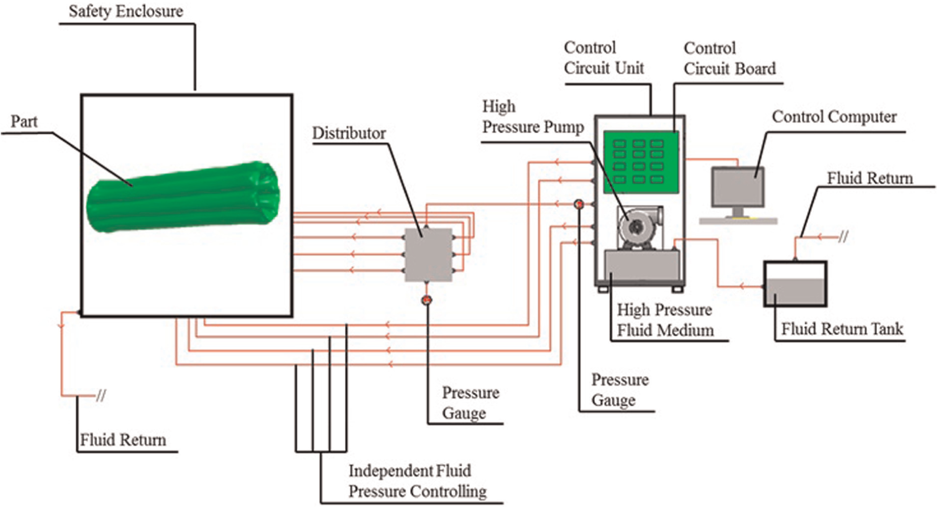
Schematic of the die-less hydroforming system.
Preparing the blanks to be hydroformed is the most time-consuming part of the die-less hydroforming process. This preparation can be done in a number of ways and depends on the desired geometry. For high-volume manufacturing, advanced blank cutting systems, water jet cutting systems, and so on can be utilized to decrease time and increase accuracy. Advanced welding techniques such as laser welding can also be used to reduce time and create fluid tight welds that will not leak. In addition to machining the geometry and welding the edges, a fluid entry point must be designed. One way of doing this is to have a hole in one of the blanks and welding a stud with a matching hole size to the blank. This procedure adds to the cycle time; however, it is critical that it is designed properly so that the fluid does not leak during forming.
The arch geometries discussed in section “Arch structural family” can be prepared by cutting the blanks into an arch shape. There is a two-stage forming process to obtain the tubular shape of the arches through the use of sheet blanks. Figure 6 illustrates the forming process that takes place in a cross section of the arch. Four blanks are used to create the structure and are assembled in pairs, as shown in Figure 6(a). The pairs of blanks are welded together along the length of the middle of the plates and then the pairs are connected by welding the outer edges. A fluid pressure is then used to form the blank pairs into a tubular shape. After a tubular shape is achieved, the area between the blank pairs is pressurized, as shown in Figure 6(b).
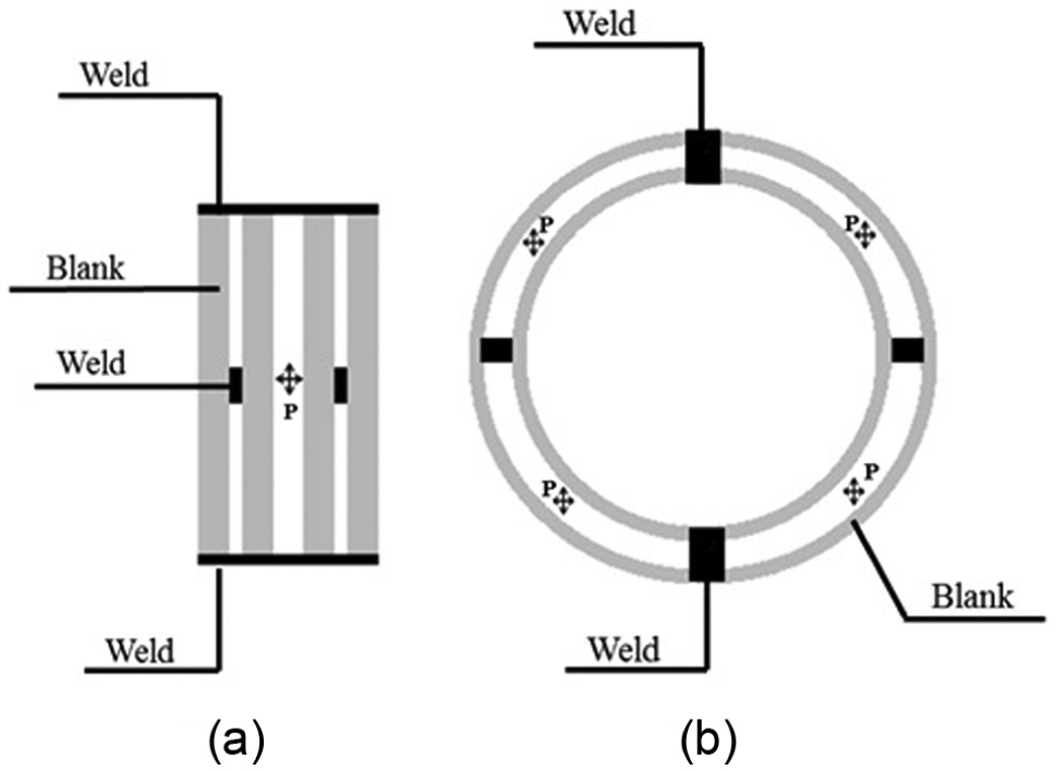
(a) First stage and (b) second stage used in the formation technique used for the arch geometry.
A helical tubular cross-sectional blank can be prepared from sheet metal, as shown in Figure 7. The sheet metal is first cut into slices at the required helix angle and welded onto a solid sheet metal. Thereafter, the sheets can be rolled into a tube and then welded again along the seam. This process is obviously time-consuming and can limit the thickness and diameter of the blanks due to rolling constraints. Depending on the type of materials, annealing may be needed to release the stresses from the rolling and welding.
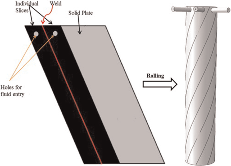
Blank setup for the tubular geometries using sheet blanks.
The highlighted families of structures in sections “Circular ring shape family,”“Tubular/shell structure family,” and “Arch structural family” indicate that die-less hydroforming process has the potential to produce complex geometries that are unobtainable through other metal-forming processes. Development of this process may lead to new product designs that were not feasible before. In the next section, parametric study of die-less hydroforming of tubular structure with complex cross section is discussed.
Parametric study of die-less hydroforming of multi-lobe tubular structures
Thin-walled cylindrical shell structures have been heavily researched in the past 50 years because of their application to several industries. Rockets, aircraft fuselages, cooling towers, silos, pipelines, chimneys, masts, and tanks are a few of the everyday applications of shell structures spanning multiple industries.10,11 These structures are used primarily because of their excellent strength-to-weight ratio and ability to handle multiple loading states.
In many applications, thin-walled shells are used for large structures in which the radius and length are magnitudes larger than the thickness. These structures can also be subjected to different loading scenarios such as axial compression, axisymmetric pressure, torsion, or internal pressure. Owing to the geometry of shells, instability and buckling are a concern, especially for large structures or ones that experience mixed loading. In order to prevent buckling, stiffeners of various shapes can be attached to either the internal or the external wall. 12 Even with stiffeners, shell buckling can still occur under certain loading conditions, as seen in Figure 2(a). Shell structures formed by die-less hydroforming such as those introduced in section “Process capabilities of die-less hydroforming” can provide a solution to the shell buckling problem. Due to strain hardening and increase in the moment of inertia through the hydroformed lobes around the shell cross-sectional area, the strength-to-weight ratio is bound to increase significantly, potentially eliminating the need for stiffeners. As discussed in section “Process capabilities of die-less hydroforming,” there are numerous unique tubular structures that can be created using die-less hydroforming. In this study, three different tubular geometries are investigated: shell/tubular structures with longitudinal lobes, circumferential lobes, and helical lobes, as shown in Figure 8.
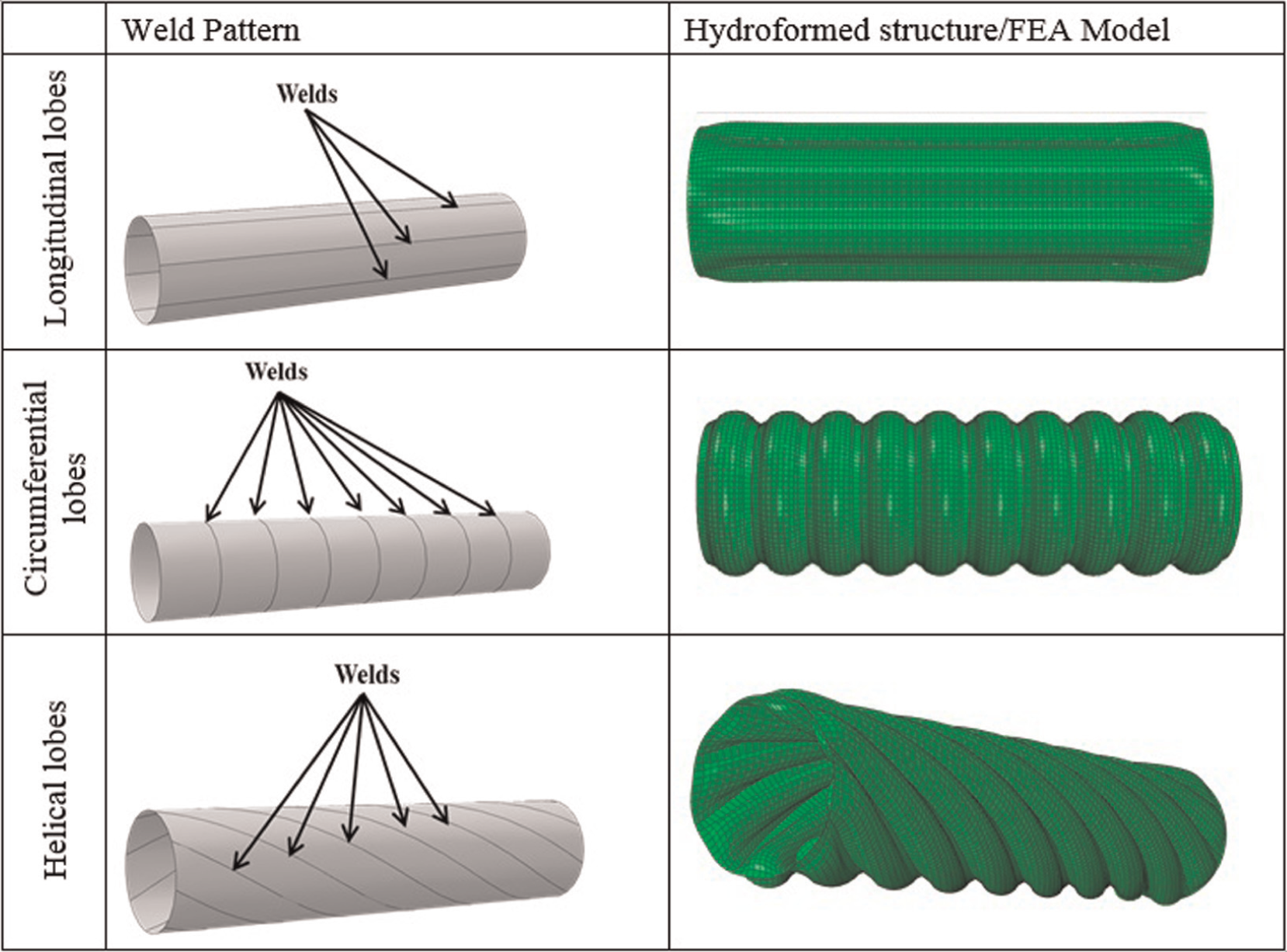
Classification of tubular geometries/FEA models.
In the course of developing these structures using die-less hydroforming, the geometrical, material, and process variables which affect forming must be defined (Figure 9). Figure 9(a) illustrates the undeformed geometry where the inner and outer blanks are welded together in some pattern at
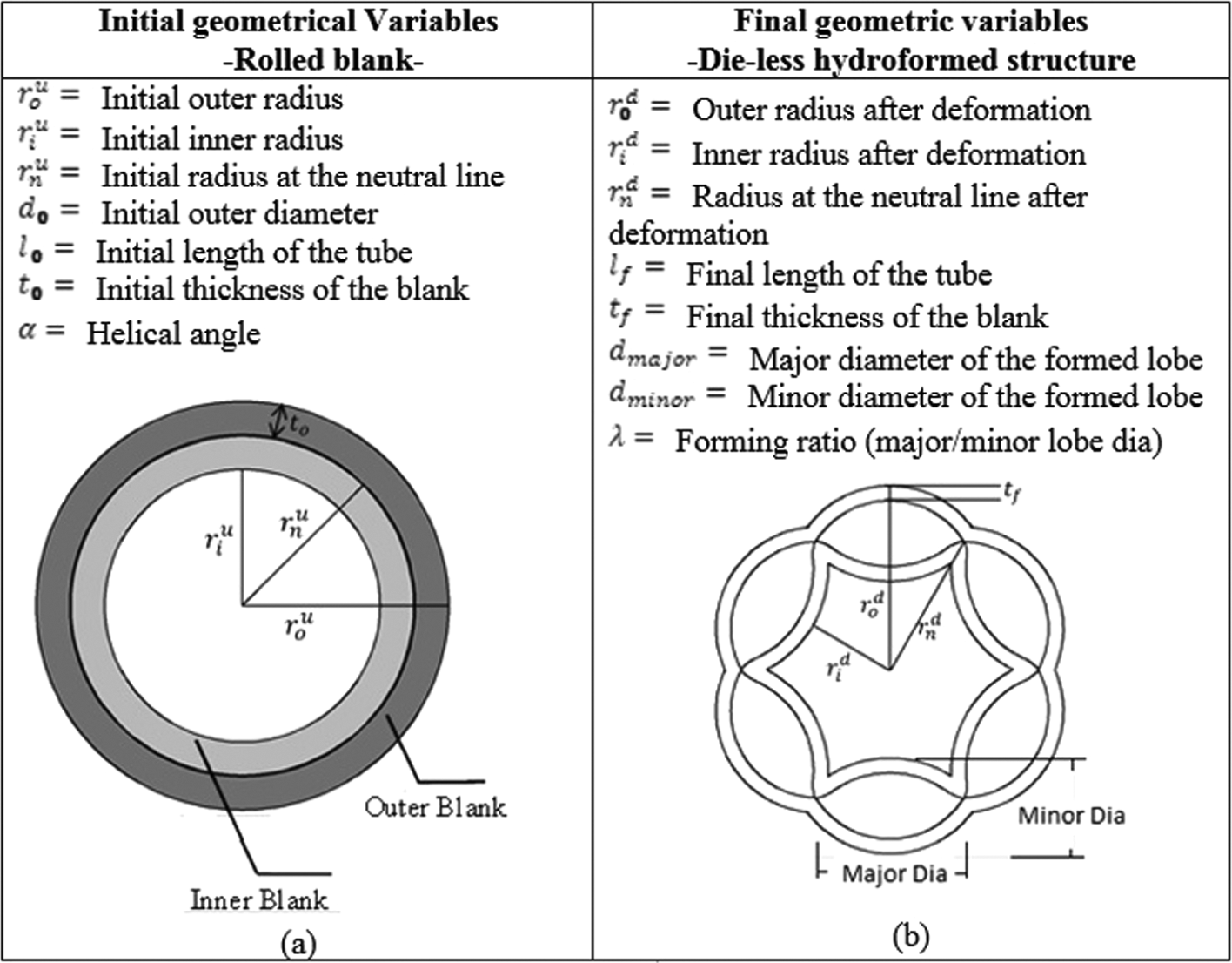
Variables for die-less hydroforming of tubular structures. (a) Tubular blank before hydroforming and (b) Hydroformed cross-section.
FEA of tubular geometries with longitudinal lobes
The investigation of these tubular structures was divided into two: load-carrying capability compared to a conventional tube with the same weight and forming characteristics of the lobes. Abaqus 6.7 FEA package was used in the study. The tubular blanks were partitioned to create several individual longitudinal sections, as seen in Figure 8. The blanks were modeled using S4R shell elements, which adhere to classical shell theory for thin-walled structures such as sheets. To simulate the attachment of the tube sections, the tie constraint in Abaqus was used. For all the simulations, the material was assumed to be stainless steel 304 and the plastic flow follows the power law,
Evaluation of load-carrying capacity for shell structure with longitudinal lobes
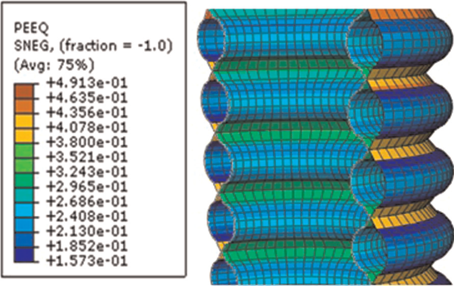
In order to assess the load-carrying capacity of longitudinal lobed shell, FEA simulations which mimic possible loading scenarios were performed on the formed lobed shell and compared with a blank shell of the same weight. A shell blank of 200 mm long and 50 mm diameter was used. The initial thickness for each of the blanks before welding partitions was 2 mm, resulting in a double wall thickness of 4 mm. The blank tube used as a baseline for these simulations was assigned a thickness of 4 mm. The simulations were carried out in two stages. In Stage I, die-less hydroforming of lobes was carried out, and in Stage II, simulations were focused on three loading scenarios: compression, torsional, and flexural. Figure 10 shows a cross-sectional view of the formed lobes and the plastic strain achieved during formation. It can be seen that a maximum strain of 0.4 is experienced during lobe formation with the average strain in the inner lobe reaching 0.25. The longitudinal lobed tubular structure was hydroformed using a maximum pressure of 65 MPa.
Plastic strain in the longitudinal lobed geometry during forming.
After die-less hydroforming simulations are completed, the deformed geometries were imported into the second-stage simulation environment with the stress and strain values still attached to the nodes. This ensures that the strain-hardening effects are still considered in the strength tests. The boundary conditions used in the FE analysis for the compression simulations are depicted in Figure 11. One end of the tube is constrained in all directions, while the opposite end is loaded toward the constrained end. The constraint is applied to the area around the tube 10 mm from the bottom edge since lobe formation does not occur there. Also, instead of applying a concentrated load to the edge of the tube, the load was applied to a 10-mm-long surface to negate the forming effects around the edge of the tube. This was achieved by coupling the degrees of freedom of the nodes on the 10-mm-long surface with a rigid die that is prescribed a displacement. The torsional loading simulation is performed in the same way as the compression loading simulation; however, the loading die is prescribed with an angular rotation instead of translational movement. Figure 11 shows the coupling between the die and tube.
Loading and boundary conditions for the torsional and compression tests.
For the flexural scenario, two semicircular rigid dies are used to hold the tube, while a third semicircular die loads the tube perpendicular to its length (Figure 12). The holding dies are 10 mm in width and are separated by a 46.5 mm gap. The die used for loading is also 10 mm in width and is in the center of that gap. This setup was used to simulate a common three-point bend test.
Cross-sectional view during bending loading for the (a) longitudinal lobed geometry and (b) blank tube and (c) an overall view of the test.
Compression loading. The tubular structure with longitudinal lobes exhibited considerable strength when subjected to compressional and flexural loading. As shown in Figure 13, the longitudinal lobed geometry was much more resistant to deformation during compressive loading than the blank. It is observed that in the low-stroke range, which is most applicable to real-life scenarios, the longitudinal lobed geometry is able to carry significantly more load than the blank. At 10 mm stroke, the hydroformed geometry carries 135% more load than the blank (Figure 13). Due to the geometry of the lobes, the structure begins to fail before the blank tube. After a stroke of 15 mm, failure is observed and the load begins to drop rapidly because of localized buckling at the middle of the tube, as shown in Figure 13. At this failure stroke, the load for the longitudinal lobed geometry is 91% higher than the blank tube.
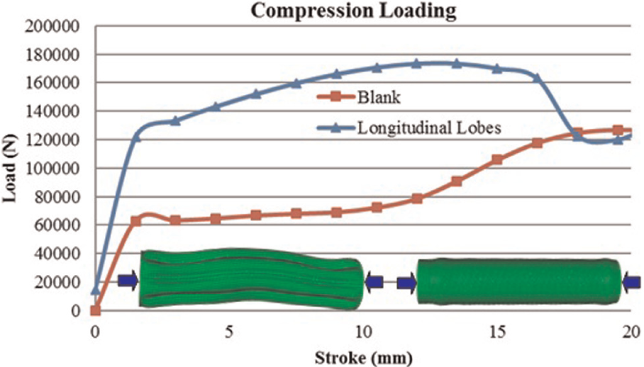
Compression load capacity for the longitudinal lobed structure.
Flexural loading. For the flexural simulation, the blank and longitudinal lobed geometry exhibited similar load–displacement curves, which are plotted in Figure 14. Again, it can be seen that the lobed structure shows an increase in strength, particularly at lower stroke. At a stroke of 3 mm, the hydroformed part carries 133% more load than the blank tube. The hydroformed part shows good rigidity and retention of tubular shape. The FEA presented above clearly shows that the longitudinal lobed geometry formed via die-less hydroforming has a significantly higher strength-to-weight ratio than a blank tube.
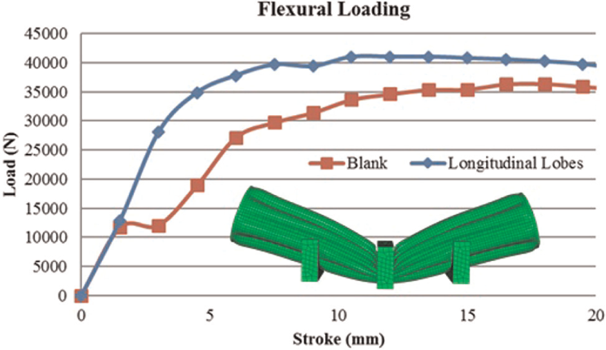
Bending load-carrying capacity for the longitudinal lobed structure.
Forming characteristics
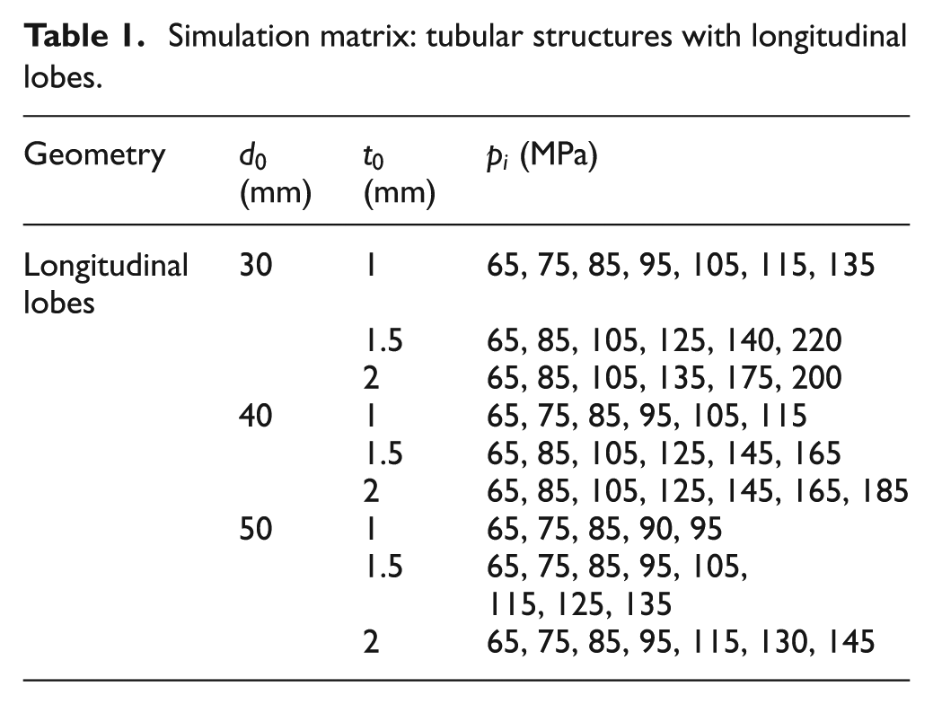
The forming profile of each of the tubular geometries is dictated by the welding pattern. In order to be able to describe the forming quantitatively, the lobes were analyzed using data from FEA solutions. The lobes are used not only to describe the forming characteristics of the tubes but also can be used for design purposes. When designing a tubular structure for a particular application, two critical geometrical variables are the inner and outer diameters. Since the hydroforming of the tubes can drastically change the profile, it is necessary to determine the relationship between variables such as initial diameter, initial thickness, forming pressure, and forming profile. Once these relationships are established through FEA, the results can be used to create a process window in which the forming pressure and lobe formation of a tube of a certain diameter or thickness can be predicted. In order to determine the deformation characteristics based on initial parameters, a range of pressures was applied while varying the thickness and diameter. Table 1 shows a simulation matrix that was used to study forming characteristics of tubular structure with longitudinal lobes. After forming, the coordinates around one of the formed lobes was plotted in order to determine the forming profile. Also, the maximum thinning was taken into account as well with the assumption that a thinning of greater than 20% indicates failure.
Simulation matrix: tubular structures with longitudinal lobes.
To investigate the forming characteristics of the longitudinal lobed geometry, a length-to-diameter (L/D) ratio of 5 was held constant. Figure 15 illustrates the lobe formation for a longitudinal lobed specimen of 30 mm diameter with 1 mm wall thickness. It can be seen from the figures that the lower portion of the lobe, which corresponds to the inner blank, exhibits different forming characteristics than the upper portion. There is a deep bulge in the middle, while the area close to the welds remains relatively flat. Also, since the bottom portion of the lobe experiences more expansion than the upper portion, the tied nodes which correspond to the weld shift downwards, allowing for the upper portion of the lobe to maintain the same outer radius from the center of the tube. A similar pattern of lobe formation was observed for the other sets of diameters and thicknesses.
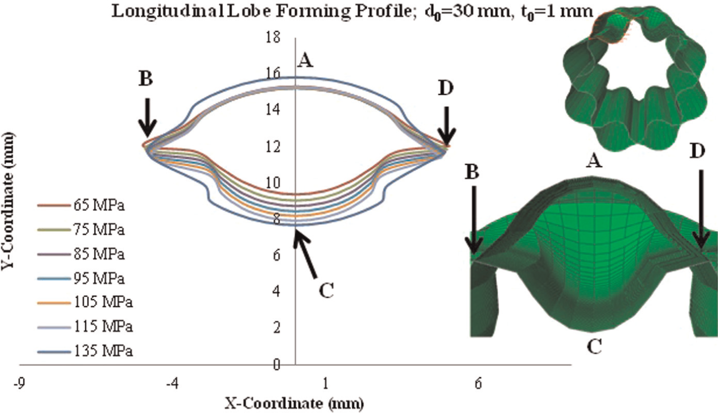
Lobe-forming profile for the longitudinal lobed geometry for L/D = 5.
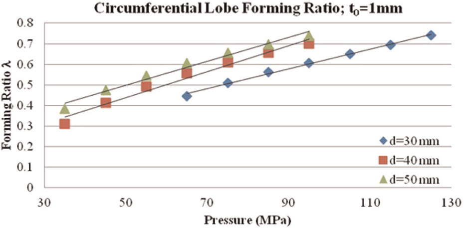
In order to quantitatively define the deformation of the lobe, a forming ratio was introduced as λ = (dminor/dmajor). See Figure 9(b) for geometrical illustrations of the forming ratio. From this definition, it can be inferred that a forming ratio of 1 indicates a circular lobe. Figure 16 illustrates the forming ratio versus pressure for each of the diameter and thickness variations. As expected, the forming ratio at a given pressure increases with increasing diameter. This indicates that tubes with smaller initial outer diameters, such as the 30 mm one, will require relatively higher forming pressure as compared to a 50-mm-diameter tube to achieve 100% forming ratio. Also, as the individual tubes become thicker, the pressure must be increased in order to form. Each variation was initially formed using 65 MPa, and then, from those results, a pressure window was determined. It can be seen that in this pressure range, the forming ratios linearly increase with increasing pressure. This is an important characteristic for design of tubular geometries. Only the results for 1 mm tube thickness are shown in Figure 16. Tubes with 1.5 and 2 mm wall thicknesses exhibited the same trend.
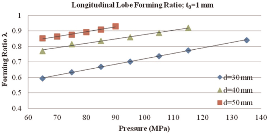
Forming ratio versus pressure for longitudinal lobed structure, to = 1 mm.
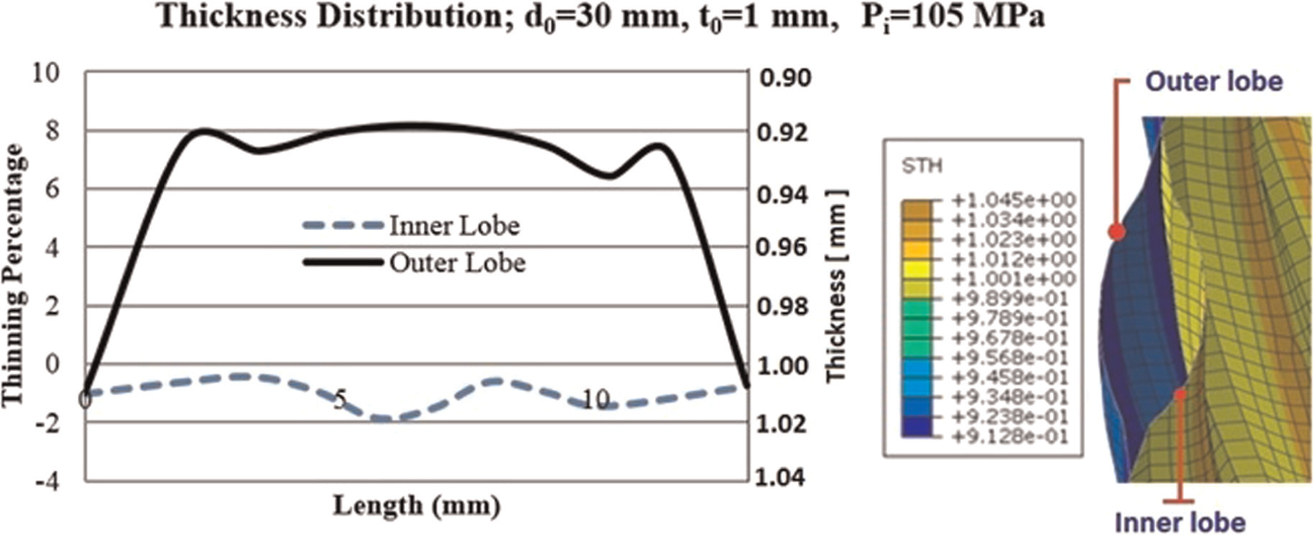
It is also important to determine the relationship between thinning and the initial geometrical parameters in order to predict a safe range of pressures in which failure will not occur. Figure 17 shows the thinning percentage for a path around the lobe. It was seen earlier that the inner and outer portions of the lobe experience different forming mechanisms; therefore, it is expected that they would exhibit different thinning characteristics. The inner portion of the lobe is initially subjected to compression and thus does not show as much thinning as the outer lobe. As expected, the greatest thinning occurs near the tie constraint which simulates the weld. Figure 18 shows the thinning versus pressure curves for each diameter and thickness set. The thinning value for this figure corresponds to the highest thinning percentage experienced by the part. Again, there is a linear relationship noted between the thinning percentage and the pressure until the thinning percentage reaches above 20% when the relationship starts to exhibit nonlinear trend. The thickness versus pressure curves are pivotal to understanding the maximum forming ratio that is allowed and at what pressure it is safe to form a particular geometry. The observed linear relationships are also useful in the design of a particular tubular structure since the data can be easily interpolated. A safe forming window for this geometry can be estimated for tubes of different initial diameters and thickness. It should be noted that similar trends were observed for 1.5 and 2 mm tube wall thicknesses as well. The study also found that forming characteristics are independent of the tube L/D ratio.
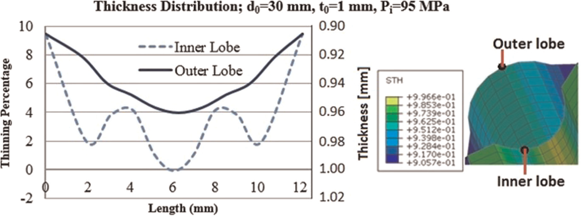
Thickness distribution for a longitudinal lobed geometry.
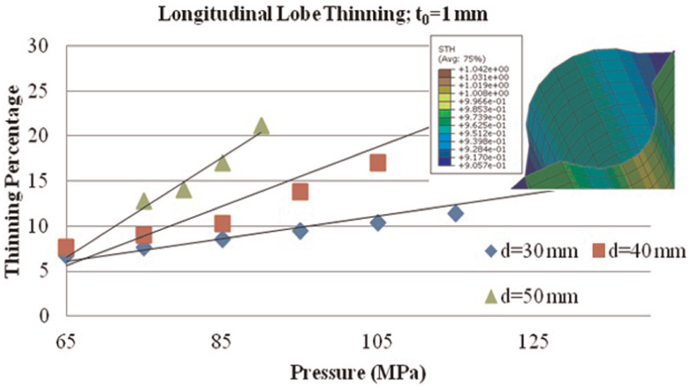
Lobe wall thinning versus pressure for longitudinal lobed geometry, to = 1 mm.
FEA of tubular geometries with circumferential lobes
Evaluation of load-carrying capacity for shell structure with circumferential lobes
The tubular geometries with circumferential lobes were subjected to torsional load and bending load simulations. The geometry was formed using a maximum pressure of 95 MPa and reached plastic strain values of 0.49, as shown in Figure 19. The average strain around the lobes was 0.24.
Plastic strain in the circumferential lobed geometry during forming.
Torsional loading. For the torsion-loading simulation, the circumferential lobed structure requires a significantly higher torque in order to deform through twisting as compared to the blank tube. As shown in Figure 20, at 17° twist, the load required for the circumferential lobed geometry is 250% higher than the blank tube.
Flexural loading. For the flexural loading simulations, the hydroformed part once again showed higher strength than the blank tube, as illustrated in Figure 21. The circumferential lobed geometry required over 10,000 N of force more than the blank tube in order to achieve the same stroke for the duration of the trial. At a low stroke of 3 mm, the hydroformed part required 174% more load. This indicates that a die-less hydroformed circumferentially lobed tube will withstand a significantly larger amount of load before deflection commences.
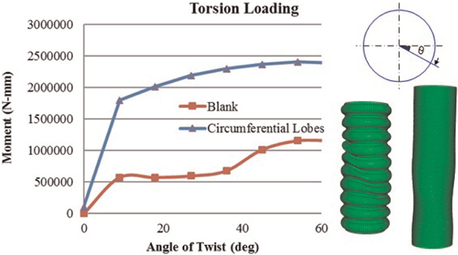
Moment carrying capacity for the circumferential lobed structure.
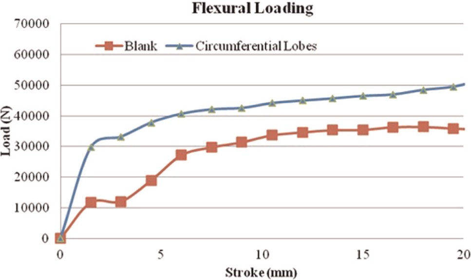
Bending load-carrying capacity for the circumferential lobed structure.
Forming characteristics
The circumferential lobed tubular geometry attaches the inner and outer blanks together through circumferential welds along the length of the tubes. For this structure, the number of welds and the length of the tube determine the spacing in between the welds and therefore determine the forming pattern. The simulation matrix used to study forming characteristics of circumferential lobes is given in Table 2. In order to maintain consistency for all tube sizes, the total number of welds and the length of the structure were held constant. The welds were spaced at 15 mm and the tube length was kept at 150 mm.
Simulation matrix: tubular structures with circumferential lobes.
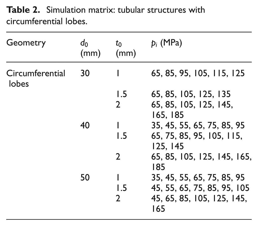
Figure 22 shows the forming profile for a circumferential welded tubular structure of diameter 30 mm and wall thickness 1 mm. From the forming profile, it can be seen that the lobes of the circumferentially welded structure deform differently from the vertically welded structure. The primary difference is that the inner and outer portions of the lobe deform nearly symmetrically about the initial neutral line
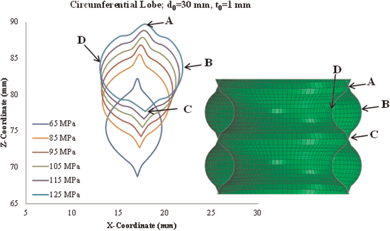
Lobe-forming profile for the circumferential weld geometry with an initial diameter of 30 mm and thickness of 1 mm.
Similar to the longitudinal lobed geometry, the circumferential lobed geometry also shows that the forming ratio increases linearly with increase in pressure for all tube sizes studied, as shown in Figure 23. While the forming ratio is higher for a larger diameter at a given pressure, the difference is not as significant as that observed with longitudinal lobed geometry.
Forming ratio versus pressure for circumferential weld geometry with initial blank thickness of 1 mm.
The circumferential lobed geometry exhibits a unique thickness distribution as well. Figure 24 shows the thinning percentage of the inner and outer lobes for do = 30 mm, t0 = 1 mm, and Pi = 95 MPa. The outer lobe experiences up to 18% thinning, while the inner lobe thickens by over 12%. This can be attributed to the compressive stress state in the inner lobe and the tensile stress state in the outer lobe. Because the circumferential and helical lobed structures shrink in the Z (longitudinal) direction as deformation progresses, the inner lobes are constrained from expanding freely. For example, if the tensile stress (sigma z) in the outer lobes is higher than the corresponding tensile stresses in the inner lobes, then part of the inner lobe will be subjected to compressive stresses leading to wall thickening. Figure 25 shows the influence of tube sizes on thinning percentage. Greater thinning is achieved at lower diameters contrary to the thinning trend observed with longitudinal lobed geometry.
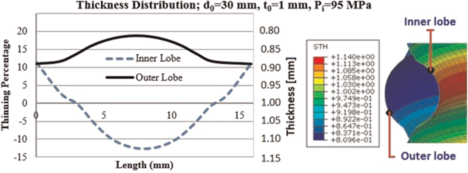
Thickness distribution for a circumferential lobed geometry of d0 = 30 mm, t0 = 1 mm, and forming pressure of 95 MPa.
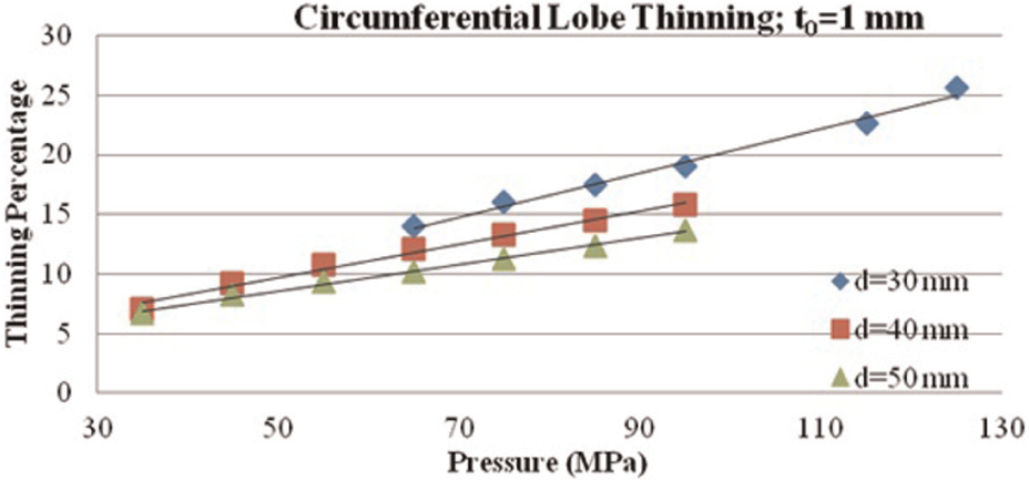
Thinning versus pressure for circumferential weld geometry with initial blank thickness of 1 mm.
FEA of tubular geometries with helical lobes
Evaluation of load-carrying capacity for shell structure with helical lobes
Torsional loading. As shown in Figure 26, the helical geometry deforms very differently when subjected to a torsional load in the clockwise direction versus the counter-clockwise direction. The picture embedded in Figure 26 shows the geometry with a clockwise load in which the diameter of the tube slightly increases as the weld lines straighten out, while in a counter-clockwise load, the diameter shrinks in the middle. Figure 26 shows that the helical geometry exhibits much better strength when the load is applied in the clockwise direction. The helical lobed structure was able to carry more load at each degree of twist while remaining in tubular shape, particularly in the early onset of torsion. At an angle of 8°, the helical geometry carried 150% more load than the tubular blank under clockwise torsional load and 92% under counter-clockwise loading. The counter-clockwise torsional loading capacity is surpassed by the blank after 50°, in which case the tube is likely fractured.
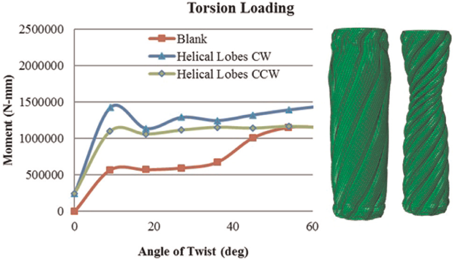
Moment carrying capacity for the helical lobed structure.
Compression loading. For the compression loading scenario, it is again seen that the hydroformed part exhibits much higher strength at initial loading. As shown in Figure 27, at a stroke of 6 mm, the helical geometry is subjected to 157% more load than the blank tube. The helical tube does begin to fail early though.
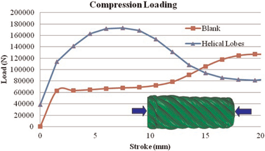
Compression load-carrying capacity for the circumferential lobed structure.
Forming characteristics
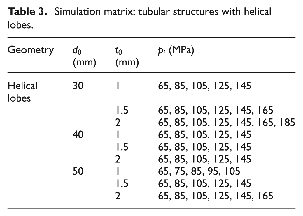
The helical geometry features six welds that wrap around the length of the tube in a helical manner. The welds begin every 45° around the diameter and complete a 315° rotation around the tube. The simulation matrix that was used to study forming characteristics for helical lobes is given in Table 3. Like the vertical weld geometry, an L/D ratio of 5 was held constant for the helix analysis.
Simulation matrix: tubular structures with helical lobes.
The helical lobed geometry provides one of the most interesting forming characteristics. As the lobes are pressurized, a twisting of the tube occurs. The profiles of the formed lobes at different pressure levels are shown in Figure 28. It can be seen that the lobes translate with the increasing pressure as the tube begins to twist while increasing the forming ratio. Also, the upper and lower portions of the lobes form almost symmetrically about
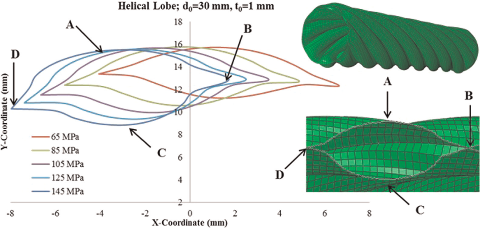
Lobe-forming profile for the helical weld geometry with an initial diameter of 30 mm and thickness of 1 mm.
The influence of initial tube diameter on forming ratio is given in Figure 29. The forming ratios vary linearly with pressure for all tube sizes analyzed. For this structure, forming ratios of over 0.8 were achieved without significant thinning.
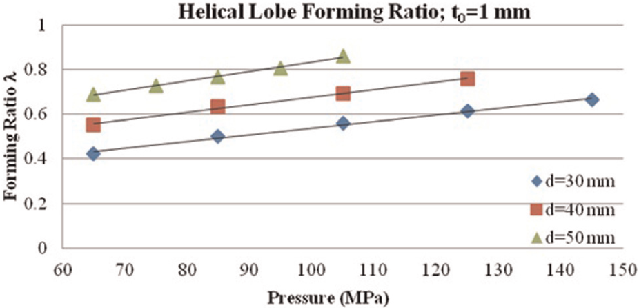
Forming ratio versus pressure for helical weld geometry with initial blank thickness of 1 mm.
The thickness distribution for the helical lobed geometry follows the same pattern as the other structures in that the outer lobe experiences thinning, while the inner lobe thickens. For this geometry, there is no significant amount of thickening in the inner lobe, as shown in Figure 30. The thickness versus pressure for each of the diameter and thickness sets is shown in Figure 31. A linear relationship is again noticed at levels under 20% thinning.
Thickness distribution for a helical lobed geometry of d0 = 30 mm, t0 = 1 mm, and forming pressure of 105 MPa.
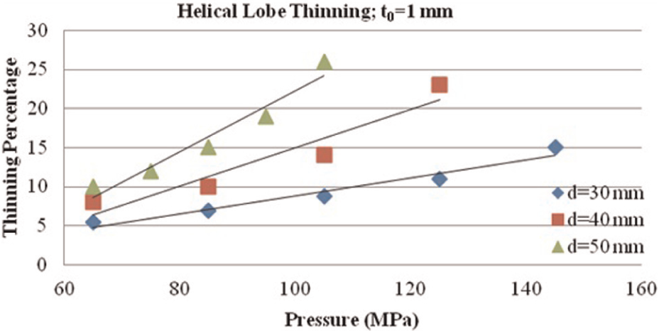
Thinning versus pressure for helical weld geometry with initial blank thickness of 1 mm.
Comparison of the deformation behavior among three multi-lobe tubular structures
The three multi-lobe tubular geometries were chosen to study lobe formation from 0° to 90° lobe orientation. The circular lobe tube represents 0° orientation and the vertical lobe 90° orientation, while the helical lobed geometry represents the transition between 0° and 90° orientations. The three tube variants have exhibited different forming characteristics. They have also showed different load-carrying capabilities. Since most structures are usually subjected to multiple loading states such as compression and bending, torsion and bending, and so on, the information obtained from the FEA simulations provides valuable guidance for the design of tubular geometries that may be suitable for specific applications. It should be noted that simulation results presented in this study assume a maximum thinning rate of 20%. This corresponds to materials with good formability. If the material has low formability, the maximum thinning rate before failure will also be lower. As a consequence, the forming ratio λ (major/minor lobe diameter) for the multi-lobe geometries will also be lower.
Experimental trials
To demonstrate the viability of the process, longitudinal lobed stainless steel tube sample (SS 304), 50 mm in diameter, 200 mm long, with 2 mm wall thickness was used in the experiment. To prepare the multi-lobe blank, six segments of equal size were first cut from a tube. These segments were then welded onto a 50 mm diameter tube. Figure 32(b) shows a cross-sectional sketch of the welded blank. To provide high-pressure fluid entry to the six lobes, six threaded hollow studs were welded to the blank. Figure 32(a) shows the tube sample with six hoses connected to the main distributor housing. Prior to hydroforming, the SS 304 blanks were annealed by heating to 1010 °C followed by rapid cooling. The THF test rig developed at North Carolina State University was used to supply high fluid pressure (Figure 32(c)). To comply with FE simulations carried out, the fluid pressure was varied linearly from 0 to 65.5 MPa.
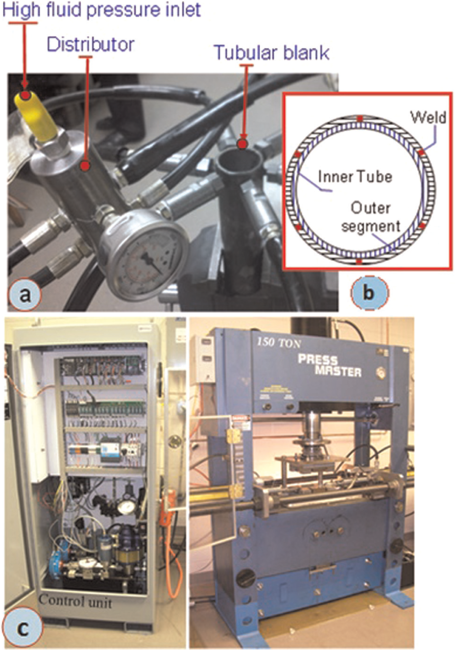
Hydroforming fluid system: (a) sample and fluid inlet pressure lines, (b) blank weld arrangement, and (c) pressure intensifier and control circuitry
Figure 33 shows the outer view of the hydroformed tubular structure and a corresponding FEA model. The high arcs corresponding to the lobes coupled with the valleys from the weld provide a unique, complex geometry. To closely observe the lobe formation, the tube was cut, as shown in Figure 34(a). A corresponding FEA model for the cross section is also shown in Figure 34(b). It can be seen that one lobe (top) experienced more deformation than the other lobes. It was observed in the early stages of pressurization that this lobe was forming more rapidly than the others. This is due to the fact that the lobes did not have independent fluid pressure control and that one lobe could start to deform before the other ones.
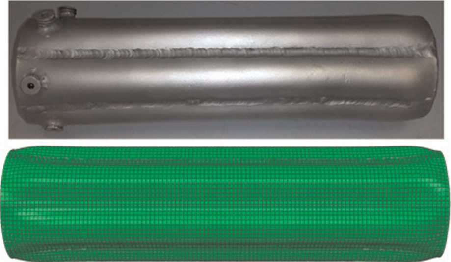
Comparison of the deformation of the body of the tube between the FEA results and the experiment.
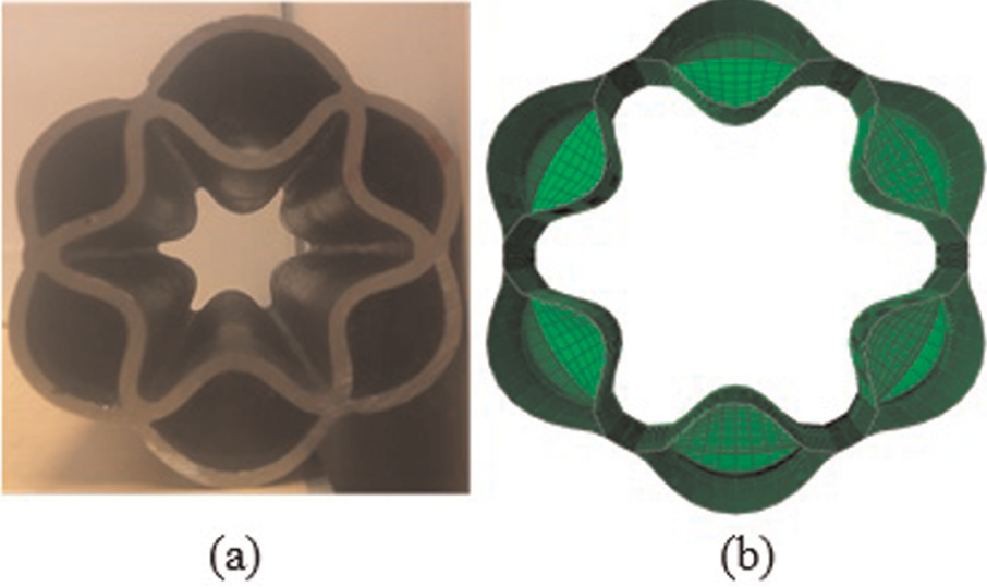
Comparison of the deformation of the lobes between the FEA results and the experiment. (a) Hydroformed part and (b) FE simulated model.
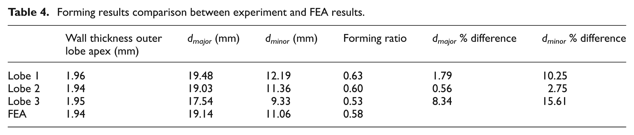
To quantitatively validate the FEA model with the experiment, the major and minor diameters of each of the lobes were measured. Since the FEA model shows uniform deformation in each lobe, only one lobe is analyzed. The measured values are listed in Table 4. The largest discrepancy occurs in the lobe that formed more rapidly than the others. However, it can be seen that there is a good agreement between the experiment and FEA.
Forming results comparison between experiment and FEA results.
Conclusion
Potential geometries that can be produced by die-less hydroforming process were investigated. FE simulations were carried out to study the deformation characteristics of three multi-lobe tube geometries: longitudinal lobed geometry, circumferential lobed geometry, and helical lobed geometry. Experimental validation was also carried out for longitudinal lobed geometry. The major conclusions drawn from this study are as follows:
The longitudinal lobed geometry has a unique lobe-forming mechanism where the inside portion of the lobe deforms more rapidly than the outside portion. Linear relationship between pressure and tube wall thickness was observed. The longitudinal lobed geometry proved to be beneficial in cases of compressional and flexural loading. In compression, the longitudinal lobed geometry was able to carry 135% more load at a 10 mm stroke than a tubular blank with the same weight. During flexural loading, the geometry carried 133% more load at a 3 mm stroke.
For the circumferential lobed geometry, the inner and outer lobes form symmetrically about the neutral line. Due to the radial bulging, as the lobes form, the tube length reduces in the direction of the constrained end. Linear relationship between pressure and tube wall thickness was also observed with this geometry. The circumferential lobed geometry showed excellent strength in torsional and compressive loading. For torsional loading, the geometry carried 250% more load than a tube blank at 17° rotation while carrying 174% more load at 3 mm stroke in compression.
The helical lobed geometry provided the most unique forming characteristics of the tubular structures. Owing to the welding pattern, the tube experienced a rotation during forming. Similar to the other geometries, linear relationships between pressure and tube wall thickness were also observed. The helical lobed geometry proved to be beneficial in torsional and compressive loading. The strength of the tube, however, varied significantly depending on the direction of the applied moment for torsional loading. With a clockwise applied moment, the helical lobed geometry carried 150% more load than a blank tube at 8°, while carrying 92% more load when a counter-clockwise moment was applied. For compressive loading, a 157% higher load-carrying capacity was seen at a stroke of 6 mm.
For all the geometries studied, the wall thickness on the inside part of the lobe became thicker, while the outer lobe experienced significant wall thinning. This is due to the compressive stress state induced in the inner lobe as it is being deformed against its neutral radius of curvature.
The geometries analyzed in this study exhibited linear relationships for variables such as forming ratio versus pressure, wall thinning versus pressure, and so on. This characteristic is very beneficial for tubular design, that is, process windows could easily be constructed via interpolation and extrapolation to estimate the proper forming pressure and other geometrical variables for desired tubular structures.
The preliminary experimental trial confirmed the viability of die-less hydroforming as a process to create a unique work-hardened structure.
Although die-less hydroforming is capable of producing complex geometries and does not require dies or presses, the manufacturing aspects of die-less hydroforming present several challenges due to the combination of processes such as welding, cutting, and rolling that may be required to prepare the blank. Depending on the welding and preformed geometry of the blank, cycle time can be high for blank preparation in this process. Also, material flow behavior through the welds may present deformation challenges.
Footnotes
Declaration of conflicting interests
The authors declare that there is no conflict of interest.
Funding
This research received no specific grant from any funding agency in the public, commercial, or not-for-profit sectors.