
Abstract
Efficient construction in three-dimensional working procedure model has an important effect on the efficiency and quality of machining process planning. This article proposes an algorithm to mapping machining features to manufacturing feature volumes from B-rep of mechanical part, and then, the working procedure models are generated. The mapping strategy is performed in three steps. In the first step, three types of machining features, such as depression feature, protrusion feature and transition feature, are introduced. In the second step, the edges of the chosen seed face and its neighboring faces are searched in order to generate the machining feature faces. The last step applies a closure to the machining feature faces to generate a compact solid by applying additional neighboring faces and their extensions. Then, the working procedure models are formed by combining the mapped manufacturing feature volumes with the final parts model. Compared with the existing working procedure model’s generation methods, this approach can avoid the unnecessary conversions from the engineering drawing to three-dimensional process models and from the machining knowledge to the modeling knowledge, which can greatly reduce the planning time on modeling. To validate the feasibility and validity of this approach, two machined parts with complex machining features are tested in the developed prototype computer-aided process planning system.
Keywords
Introduction
Nowadays, with the development and application of three-dimensional (3D) computer-aided design (CAD) technology, three-dimensional models are running through the entire life cycle, such as the design stage, the process planning stage, and the manufacturing stage. In order to reduce the process planning time and increase the consistency and efficiency, computer-aided process planning (CAPP) systems gradually apply the three-dimensional data model, because it contains a great deal of process information, such as the features of geometry, the precision of surface, and topological relations.
The machining process of machined parts is a dynamic evolution process. It starts with the blank part and applies operations to each face/feature until it reaches the finished part model. 1 Three-dimensional working procedure model (WPM), which reflects the changes on geometric shapes and dimension in machining stage, is especially critical to digital manufacturing. 2 The input model of CAPP systems is the final part model but it is not the blank model. Based on the design part model, how to create the WPMs in the different manufacturing stages is becoming the thorny problem. Creating the WPMs has become a bottleneck in the development of the machining process planning system. 3 In this article, a method on how to rapidly and efficiently construct the WPMs is proposed. The general idea can be explained as follows:
Recognizing the machining feature faces. The seed face which is selected by the interactive mode is used, and then the feature surfaces of the selected machining feature are identified by the proposed recognition algorithm.
Forming the manufacturing feature volume (MFV). We apply a closure to the machining feature faces to generate the MFV by its neighboring faces and their extensions.
Constructing the WPMs. The WPMs are generated by combining the formed MFVs with the finished parts model in the generation sequence. This generation sequence of the WPMs is reverse to the machining process, which is from the work blank to the final part.
It is worthwhile to construct the WPMs in the machining stages. Each WPM contains the removed material volume and the finished parts state in each process. It can not only be the carrier and basis of the manufacturing information which can expediently direct the downstream manufacturing applications but also avoid the ambiguous expression. Moreover, it would be useful in the following digital manufacturing scenarios, such as computer numerical control (CNC) programs, reuse of the process information, three-dimensional fixture design, and evaluation of the process plan.
The proposed method will be illustrated in the following sections. The next section reviews the existing research works relevant to the WPM construction methods and the feature recognition technology. Section “Basic concepts” presents the basic definition of machining feature, machining feature faces, MFV and WPM. Section “The proposed algorithm” explains the recognition methods of the machining feature faces and the mapping strategy of the machining feature. Section “Case study” presents two case studies to demonstrate the capability of the proposed algorithm. Finally, conclusions and future work are presented.
Literature review
With the development of digital manufacturing technology, CAPP technologies and systems are extended and modulated, then extensively used in manufacturing companies. 4 In the process planning domain for the manufacture of the part, three-dimensional working procedure modeling for complicated parts is increasingly required by aviation, aerospace, shipping and other manufacturing industries.
In machining process planning, the construction approach of the WPMs can be classified into two types: modify the design model by the manual methods and drive WPMs by the process knowledge.
With the more mature three-dimensional CAD technology, the WPMs are formed by the manual methods. Zhou et al. 5 proposed some methods to generate the WPMs on the platform of commercial CAD systems. These methods include deleting or adding the features from the design model, modifying the features on the design model. This method is low efficiency and consumes a great deal of repetitive work. In addition, the CAD system and the CAPP system might not have the compatibility, which can cause the formed WPMs not to be applied in the CAPP systems. Although this method is low efficiency, it is still used by some enterprises. The better approach has not yet appeared.
Some researchers focus on forming the WPMs by using the process knowledge. Zhang et al. 2 proposed an approach to reconstruct the WPMs by analyzing the machining operation sheets. The serial WPMs of the rotational parts are driven by process planning course, machining semantics and machining geometry. But this method is difficult to be applied to the three-dimensional manufacturing environment. Based on the relationship between the machining knowledge and three-dimensional modeling knowledge, Wan et al. 3 proposed the WPMs’ driven methods by using the model based definition (MBD) technology. Li et al. 6 proposed an automatic generation method based on the relationship between machining process information and in-process models. This method needs to express and analyze the process route based on feature working steps. When forming the WPMs of the complicated parts such as the prismatic parts, these proposed methods would be less efficient. In short, the existed methods of generating WPM not only waste a lot of time but also cause some unnecessary problems when converting the two-dimensional drawings to three-dimensional models.
Feature technology has become the de-facto standard for product modeling in CAD/computer aided manufacturing (CAM). 7 Researching in feature technology has mainly focused on feature recognition from the three-dimensional model. 8 In our research, the forming process of MFV is the key link in the approach of constructing WPM. Therefore, we take advantage of the feature technology to map the machining feature to MFV.
In the domain of feature recognition, researchers have proposed and implemented various algorithms: graph-based algorithms, volumetric decomposition techniques, hint-based geometric reasoning and hybrid approach. Comprehensive review of various feature recognition techniques has been reported in the literature.8–10
The graph-based model is first formalized. 11 In this approach, the B-Rep model of the part is translated into a graph based on the attributed adjacency graph. In this literature, the proposed method does not deal with the protrusion feature (PF) and the transition feature. This recognition algorithm is weak in recognizing intersecting feature. Later, some literatures12,13 extend this approach to resolve this problem, but these extended methods have little effect.
Volumetric decomposition techniques contain two types: convex hull decomposition and cell-based decomposition. It is first implemented by Kim. 14 Some literatures15–17 extend this approach and make efforts to decompose solid models into simpler volumes. For example, the delta volumes are decomposed into the volumes of simple machining feature by using the above-mentioned method. The composition algorithm cannot avoid the exponential time complexity. 10 Moreover, the decomposition volume does not have the manufacturability.
The hint-based geometric reasoning approach is designed and first implemented in object-oriented feature finder. 18 This approach defines geometric reasoning rules, which associate machining information to identify the machining features. An automatic feature recognition method is generated based on the feature recognition rules and feature hints. 19 This method can eliminate the difficulty in expanding an existing rule base and allow the automatic definition of feature hints in different application domains. The defects of the hint-based approaches are the difficulty in generating desirable interpretations. 10
Some researchers have integrated two or more approaches to recognize the machining features. An intelligent system 7 is developed to recognize the machining features from the prismatic part model based on graph-based algorithms and volumetric decomposition techniques. To recognize the complicated features, a new method is proposed by Sunil et al. 13 The method is formed by combining the graph method and geometric reasoning method based on the B-Rep model. It is enough to handle both the general features and intersecting features, whereas this method cannot be applied to handle the protruding features.
In the domain of feature recognition, most researchers apply this technology to convert the design features into the machining features. A geometric reasoning method is investigated to convert the design feature to the machining feature during the design process. 20 This proposed method can support the integration of the design system and the manufacturing system. A new built computer-integrated manufacturing system 21 can convert design feature into machining feature by using the rule-based algorithms. At first, this system needs to simplify the model, such as suppress the fillets. Then, the design features are converted into machining features. An incremental feature converter is proposed to extract the machining feature from feature-based design model. 22 This method can deal with feature interactions and PFs but cannot analyze the manufacturability of the machining features.
From the literature review, a great number of significant efforts have been focused on the automatic extraction machining features. Those methods can be used for three-dimensional static models, but cannot be used for dynamic models. However, WPMs can dynamically and visually display the changes on geometric shapes in machining stages. So, the automatic extraction mode of the machining features does not suit for the WPMs generation. Moreover, if the method of automatic extraction machining feature for process planning is employed, it will cause trouble in the downstream activities, such as process modification and sequence adjustment. Therefore, we propose an interactive mode to recognize the machining feature surfaces and then map the corresponding MFV.
In summary, constructing the three-dimensional WPMs in different machining stages in a rapid and efficient way is a challenging problem. 2 On considering the applying environment of CAPP in digital manufacturing, we propose a new strategy which combines the geometric reasoning knowledge with the process requirements to generate the WPM. The geometric reasoning knowledge can help to map the MFV from the machining feature. Based on the process requirements, the WPMs are constructed by the interactive mode. The obtained MFV cannot only visually describe the removed volume during each machining stage but also accurately provide the previous step parameters, such as dimension and surface precision. The proposed algorithm as a module has been applied in the developed prototype CAPP system.
Basic concepts
Definition and classification of machining feature
Feature recognition techniques have been proposed and implemented in various manufacturing areas in the past three decades. However, literature reveals that the definitions of machining feature do not have consensus. There are many different definitions in these literatures for the term “machining feature”: some works11,18,23,24 describe it as information-set relative to the manufacturing knowledge, such as machining operation and tool; some works25,26,27 deem the machining feature as a surface feature; some works15,28,29 define the machining feature as a volumetric feature.
Based on the different definitions of the machining feature, the machining feature is defined as follows: a machining feature can be represented as a set of surfaces which are formed by removing the material volume in a single operation with a single tool on a single machine.
The machining features are classified into three categories according to their forms: depression feature (DF), PF and transition feature. They are shown in Figure 1.
DF: unbroken part surface. It is indicated by the lack of internal loops and concave edges. The DF is formed on the three-dimensional part model by using the “cut” operation in the solid modeler, such as simple/tapered/countersunk hole, simple/drafted slots, pockets and grooves.
PF: an all-concave loop on a surface (not necessary in another part of boundary surface dictating some type of interaction). This surface is deemed as the part surface for the protrusion, and the PF faces are formed by removing the surrounding material. A PF is created by using the “join” operation in the solid modeler, such as boss extrudes, ribs and islands in pockets.
Transition feature (TF): it is a transition area between two surfaces. TF is a decrement or increment to the volume of a shape which depends on whether its profile is convex or concave or not in the solid modeler. Most of them can be used as the subsidiary feature, such as rounds and fillets.
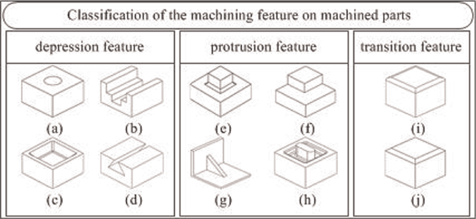
The classification of the machining feature: (a–d) depression feature, (e–h) protrusion feature and (i and j) transition feature.
Sometimes, primitive features may not exist by themselves but intersect with each other. Intersecting features are common in the complex machined parts. The interactions among features may be classified into three types: shared volume by several features, tolerance/datum dependencies and coincidental/grouping relationships. 28 This article mainly focuses on the volume intersection. Intersecting features are formed by multiple operations. It can be decomposed into some primitive features by using the machining process provided by the planner.
Machining feature face
A machining feature face is seen as a surface of the machining feature. Each machining feature corresponds to a set of machining feature face. According to the classification of the machining feature, machining faces can be split into DF face, PF face and transition feature face. The different machining feature faces are shown in yellow color in Figure 2.
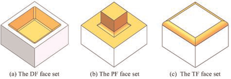
The different machining feature faces: (a) the DF face set, (b) the PF face set and (c) the TF face set.
Manufacturing feature volume
The delta volume is defined as the volume swept 18 by a cutter in machining process, while the delta volume may be larger than the amount of the removed material that is from the working blank to the desired part. The cell volume 10 is generated by decomposing the delta volume. A MFV is defined as the removed material volume when a machining feature is formed.
From the above-mentioned explanation, all the MFVs and the final part model can constitute the work blank model by unite. Thus, the relationship among them can be expressed as follows
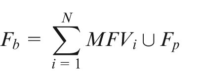
where Fp represents the feature model of final part and Fb represents the work blank.
Working procedure model
WPM is seen as the carrier of the process information to guide the downtown manufacturing activities. A WPM is generated by combining the MFV with the finished part. We only focus on the generation process of WPMs without regard to its generated sequence by considering the uncertain process planning of the single and small batch production of complex parts. The machining sequence is confirmed by the machining acquirements and the process knowledge. The sequence of the generated WPMs is inverse to the machining sequence (Figure 3) because the MFV is obtained from the final part model. WPM i (i = 1, 2, 3, 4) represent the ith WPM.
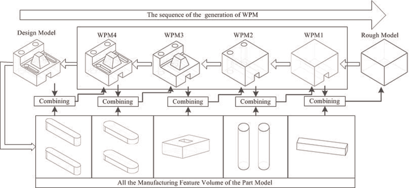
Constructing the WPM based on combining the MFV with finished part.
The proposed algorithm
The manufacturing process of a machined part starts with the work blank. However, in the most digital manufacturing industries, the process of the process plan starts from the final part model. In this article, the machined part is represented by boundary representation (B-Rep) as the input date model to the feature recognition algorithm.
Overviewing the algorithm
The construction of WPM focuses on two key issues: recognizing the machining feature faces and forming the MFV. Identifying the machining feature faces is a pre-requisite for the mapping strategy. The geometric reasoning knowledge is used to recognize the machining feature faces. Edges can be classified to as concave edges, convex edges and tangent edges 30 . This classification will facilitate the implementation of the proposed methodology.
The overall procedure of the developed algorithm is shown in Figure 4. First, the machining feature faces and its neighboring faces are identified by the geometric reasoning method. Then, applying a closure to the machining feature faces to generate a compact solid by using the neighboring faces and their extensions faces. The compact solid is regarded as its corresponding MFV. The recognition rules of geometric reasoning and the mapping strategy will be explained in the following sections. Finally, the WPM can be constructed by combining the MFV with the input part model.
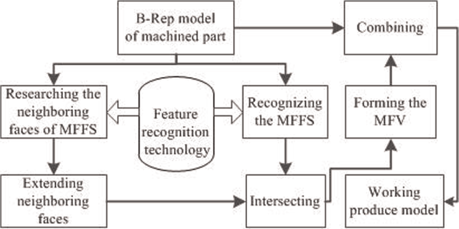
The construction algorithm of the WPM.
Recognizing the machining feature faces
In order to recognize and obtain the constitution faces of machining feature, this algorithm takes the machining feature faces as the study object and the seed face as the research unit. During the process planning, the seed face of a machining feature is chosen by the process planner. The machining feature faces can be searched by the proposed specific recognition method and it is shown as follows:
Two face lists (Face-List 1 and Face-List 2) are created when the seed face is selected. As the output list, Face-List 2 can store all the faces which meet the rules of geometric reasoning. As a temporary list, Face-List 1 is used for saving the candidate seed faces which will be searched in the following process. The candidate seed face will match with the contained faces of the Face-List 2.
The edges of the seed face are obtained and their types are identified, then the appropriate process (process 1, process 2 or process 3) is automatically selected and the neighboring faces of the seed face are searched based on the rules of the geometric reasoning.
If the candidate seed face does not exist in the Face-List 2, the algorithm goes on, if not, delete it.
Different feature types have different recognition approaches. The specific recognition algorithm of the different feature types will be described as follows. According to the feature type of the seed face, this algorithm can automatically choose the corresponding geometric reasoning rules to get the feature faces. The algorithm of recognizing feature faces is illustrated in Figure 5.
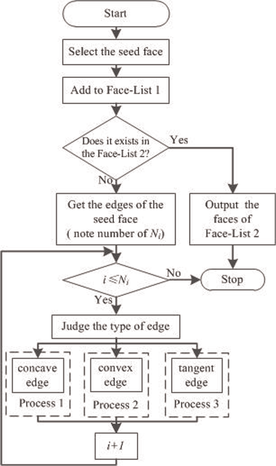
The recognition algorithm of the machining feature faces.
Recognizing the TF faces
Most TF’s shapes are fillets or chamfer and the examples of TF are shown in Figure 1(i) and (j). In this article, we take the rounded shape of the TF as the research object. The TF is generated in the following two manners: one is generated by the tool shape; the other is generated based on the process requirements.
The TF is divided into two subtypes: the positive transition feature (PTF) and the negative transition feature (NTF). The PTF is generated by machining the convex edges. This process is seen as decrement volume, and the formed surfaces are called the PTF face. The NTF is generated by machining concave edges. This process is seen as increment volume, and the formed surface is called the NTF face. The identification methods of PTF and NTF are described as follows:
Selecting a TF face as the seed face. The neighboring faces are gained and judged by whether it is plane or not.
Searching all the neighboring faces and extending them until intersecting. If the intersecting edge is convex edge, the TF is the PTF, if not, it is the NTF.
The main characteristics of single TF are described as follows:
One face is non-planar.
Each TF face includes at least two tangent edges.
The neighboring planes of the tangent edge can be extended and intersected.
The curvature of TF face is greater than its neighboring faces.
After analyzing the TF, the next stage is to recognize its faces. First, a feature face is selected as the seed face by the process planner. Subsequently, the edges of the seed face are obtained by the geometric reasoning method, and then, the types of them are judged. The judgment results can be seen as the key judgment factor in the following step. The process of the next step is described as follows. The identification algorithm flowchart of the tangent edge is represented in Figure 6. The specific TF identification rules are described as follows:
If an edge is a concave edge or a convex edge, delete it and then judge the type of the other edge.
If an edge is a tangent edge, process 3 is chosen. This seed face is saved in Face-List 2 and this edge is saved in Edge-List 1.
The neighboring faces of the saved edges are obtained and saved in the Face-List 1. They are seen as the candidate seed face.
Continue the above-mentioned processes until all the TF faces are obtained. The obtained faces of the TF with the yellow color indicated are shown in Figure 10(a).
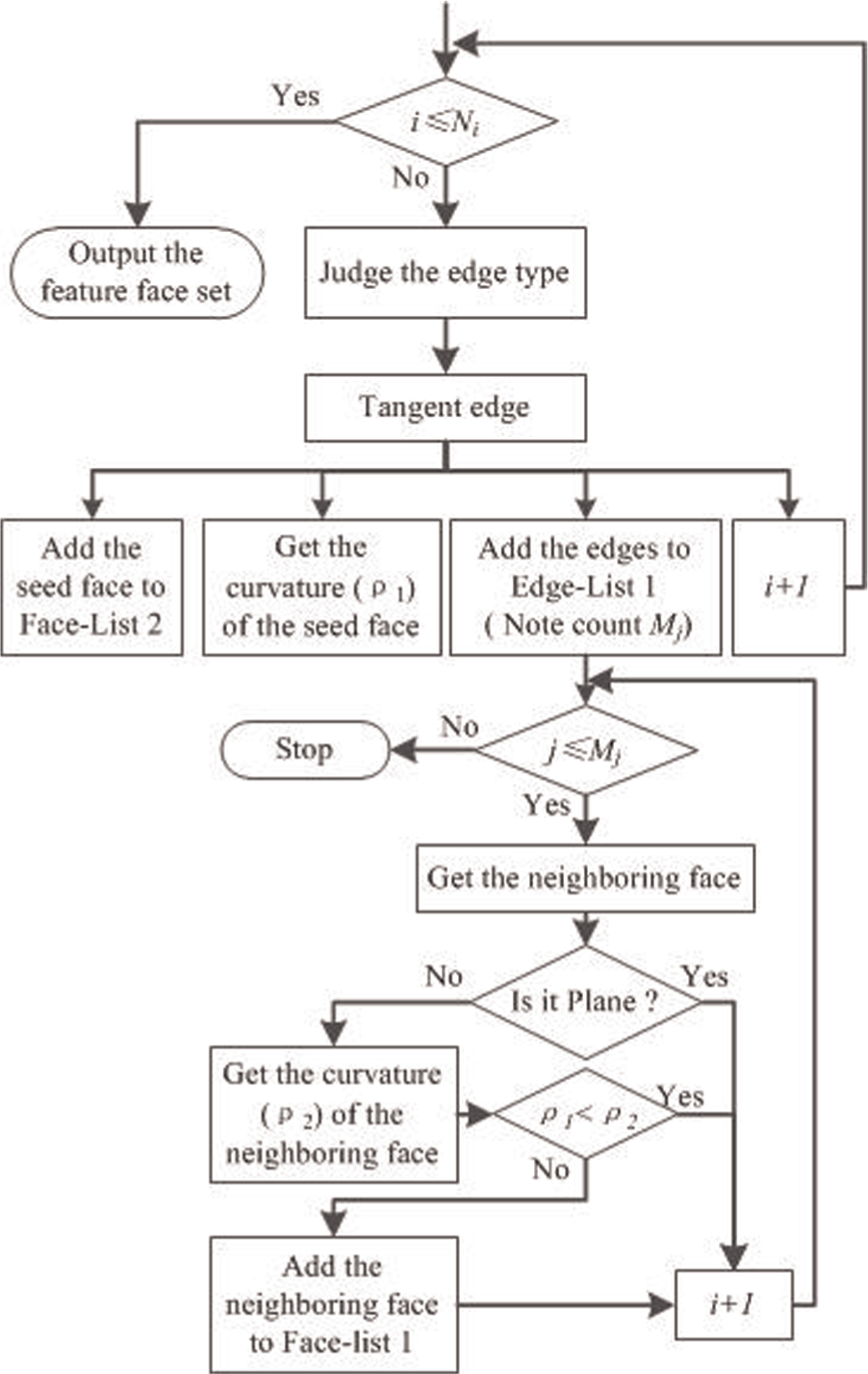
The recognition approach of the TF faces—the tangent edge.
Recognizing the DF faces
Most machining features in the machined parts are the DF. The examples of the DF are shown in Figure 1(a)–(d). The basic characteristics of the single DF (except for through-holes) are explicated as follows:
Contain at least two faces (a floor and a lateral face) of each DF.
The intersection edge which is formed by the bottom face and the lateral faces is a non-convex edge.
The edges of the floor are non-concave edges except the intersection edges which are formed by the floor and the lateral faces.
There is at least one plane along the normal direction of the floor.
After analyzing the PF, the next stage is to recognize its faces. According to the process planning requirements, process planner selects a DF face as the seed face. Let Fa1 represent the selected seed face. It is shown in Figure 8(a). Subsequently, the edges of seed face are obtained by geometric reasoning method and their types are judged. The judgment result can be seen as the key element in the following step. The identification method flowchart of the tangent edge is represented in Figure 7. Taking this DF as the case study, all the machining feature faces of the DF are recognized and the recognition processes are shown in Figure 8. The specific identification rules of the DF faces are described as follows.
If an edge is a concave edge, the process 1 is chosen by the algorithm. This seed face is added to Face-List 1 and this edge is saved in the Edge-List 1.
If an edge is a convex edge, delete it and then judge the other edge’s type.
If an edge is a tangent edge, the process 3 is chosen. This seed face is added to Face-List 2 and this edge is added to Edge-List 1.
The neighboring faces of the saved edge are obtained. Judge these faces whether they are plane or not. If the neighboring face is non-planar, judge the type of the TF face based on the identification method illustrated in section “Recognizing the TF faces.” If the TF face is the PTF face, this face is saved in Face-List 2. If it is the NTF face or the plane, it is saved in the Face-List 1 as the candidate seed face. Let Fa = {Fa1, Fa2 } represent the obtained NTF faces and they are shown in Figure 8(b).
The obtained neighboring faces which are added to the Face-List 1 are seen as the candidate seed faces. Continue the above-mentioned processes until the constitute faces of this feature are obtained. Let Fa = {Fa1,Fa2,Fa3,Fa4,Fa5,Fa6,Fa7 } represent all the obtained DF faces as shown in Figure 8(c).
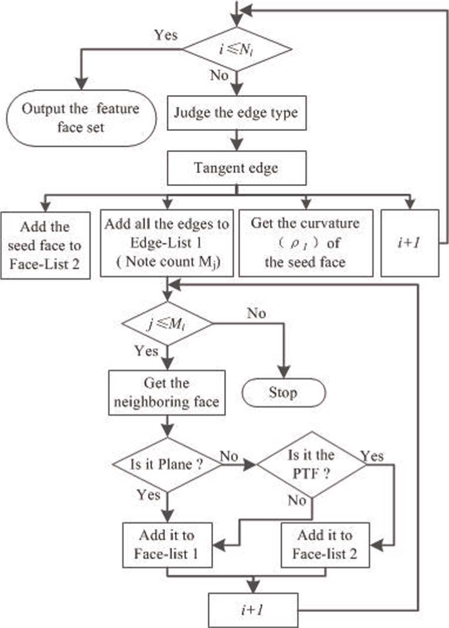
The recognition approach of the DF faces—the tangent edge.
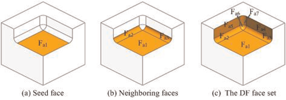
The recognition process of the DF faces: (a) seed face, (b) neighboring face and (c) the DF face set.
Recognizing the PF faces
A PF is created by removing the surrounding material from the work blank model. The examples of the PF are shown in Figure 1(e), (f) and (h). An island can be seen as the basic PF in the machined parts. The island is fixed on a face which is called the support face. The main characteristics of the PF are described as follows:
Contain one support face.
The intersecting edges which are formed by the boss feature faces and support face are the non-convex edges.
The maximum and minimum points are existed in the PF.
The process of selecting the seed face and obtaining all the edges of the seed face of the PF is same as the recognizing procedure of the DF faces. The identification rules of identifying the PF faces are described as follows:
If an edge is a concave edge or a tangent edge, delete it and then judge the other edge’s type.
If an edge is a convex edge, the process 2 is chosen. The selected face is saved in Face-List 2. And this edge is added to the Edge-List 1.
Adopt the edges of the seed face in the Edge-List 1, the neighboring faces of it are searched. The obtained neighboring faces are added to the Face-List 1 as the candidate seed faces.
Continue the process above until the constitute faces of the PF are obtained.
Recognizing the intersecting feature faces
The intersecting features cause one or more machining features which share the same face. The topology variations (variable topology) are changed even the intersecting feature leads to the multiple interpretations. The presence of intersecting feature leads to the difficulty in interpretation or the possibility of multiple interpretations.
For the machined parts, the intersecting features are formed by intersecting the DF, the TF or the PF with each other. The examples of the intersecting features are shown in Figure 1(b) and (h). In this article, the intersecting features can be classified into three subtypes and the methods of recognizing this feature faces are shown as follows:
If the intersecting feature is formed by intersecting two or more DFs mutually, it can be decomposed into one or more DFs based on the machining process requirements and it is shown in Figure 1(b). The methods of recognizing the DF faces need to refer to section “Recognizing the DF faces.”
If the intersecting feature is formed by two or more PFs intersecting together, it can be divided into one or more PFs and the identification methods of the PF faces need to consult with the illustrated algorithms in section “Recognizing the PF faces.”
If the intersecting feature is formed by the PF and DF, it is subdivided into two types: the height of the boss is equal to or less than the depth of the DF; the height of the boss is larger than the depth of the DF. The first intersecting feature is seen as the DF to be dealt with. The other is decomposed into two parts: the surrounded boss part can be seen as the DF and the rest of the boss can be treated as the PF to be dealt with.
Forming the MFV
Realizing the mapping strategy from the machining feature to the MFV needs to make full use of the mapping principle and methods. The three-dimensional B-Rep models can be seen as the foundation of the conversion and mapping. It can deliver the integrated information among the feature layers.
The analysis result of the machining feature and the identification methods of the machining feature faces can provide a favorable environment to map the MFV from the machining feature. In order to get the corresponding MFV, the mapping strategy is developed. The mapping strategy of each machining feature will be explained in details as follows.
The mapping strategy of DF
The schematic diagram of this process of the DF mapping strategy is represented in Figure 9. The specific mapping strategy is described as follows. The DF faces and the adjacent faces are obtained by using the elaboration methods in section “Recognizing the DF faces.”
Let Fd = {Fd1,Fd2,Fd3,Fd4,Fd5,Fd6,Fd7 } represent the DF faces as shown in Figure 9(a). Let Fa = {Fa1,Fa2,Fa3,Fa4 } represent the neighboring faces of DF faces as shown in Figure 9(b).
The compact volume, which is surrounded by extending the neighboring faces and the DF faces, is regarded as the corresponding MFV as shown in Figure 9(c). Vmd is supposed to be the MFV. Vmd = Fd ∩Fa is shown in Figure 9(d).
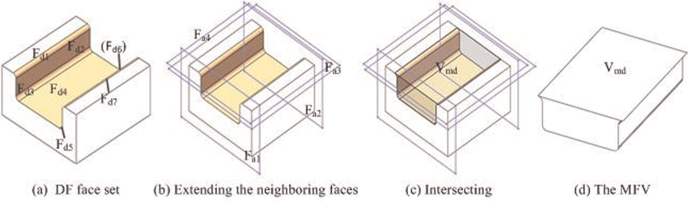
The mapping strategy from the DF to its MFV: (a) DF face set, (b) extending the neighboring faces, (c) intersecting and (d) the MFV.
The mapping strategy of TF
According to the location of the TF in machined parts, the TF is classified into two types. If the TF is seen as the subsidiary feature, it does not need to be dealt with; if it is alone, it needs to be handled by the specific mapping strategy as follows:
The TF faces and the neighboring faces are obtained by the elaboration methods in section “Recognizing the TF faces.” Let Ft = {Ft1,Ft2,Ft3,Ft4 } represent the TF faces as shown in Figure 10(a). Let Fa = {Fa1,Fa2,Fa3,Fa4,Fa5 } represent all the neighboring faces as shown in Figure 10(b).
The compact volume, which is surrounded by extending the neighboring faces and the TF faces, is known as the corresponding MFV as shown in Figure 10(c). Vmt is supposed to be the feature volume. Vmd = Ft ∩Fa is shown in Figure 10(d).
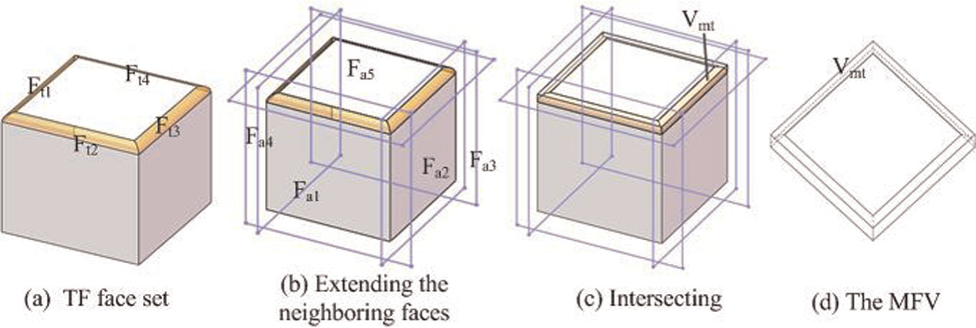
The mapping strategy from the TF to its MFV: (a) TF face set, (b) extending the neighboring faces, (c) intersecting and (d) the MFV.
The mapping strategy of the PF
Based on the generated process of the PF, it can be classified into two types and the corresponding mapping strategy is explained as follows:
If the PF is formed by casting, such as ribs (Figure 1(g)), it needs the simple operations to get the corresponding MFV. According to the processing requirements, only the constructional contact faces of this PF need to be machined. The corresponding MFV of these PF faces can be easy to be obtained by the basic modeling methods, which are provided by the commercial CAD software such as offset face.
If the PF is formed by removing the surrounding material, such as an island in pocket/slot (Figure 1(h)), it needs the specification mapping strategy. After the PF faces and its neighboring faces are recognized, the neighboring faces are extended until intersecting together, and a compact volume is formed by combining with the PF faces. The mapping strategy of this PF will be elaborated in the next section.
The mapping strategy of the intersecting feature
In machining, the intersecting feature is formed by multi-steps machining operations. Therefore, each intersecting feature can be decomposed into one or more primitive machining features. We take an island in the pocket as an example to show the mapping strategy. This intersecting feature is composed by the DF and PF based on the machining requirements. The schematic diagram for obtaining the corresponding MFV is represented in Figure 11. This intersecting feature corresponds with two MFVs as shown in Figure 11(g) and (h). The specific mapping strategy is described as follows:
The portion of the boss that is surrounded by the pocket wall is taken as the DF to be dealt with. The DF faces and its neighboring faces are obtained by using the elaboration method in section “Recognizing the DF faces.” Let Fd represent all the obtained faces as shown in Figure 11(a). Let Fa = {Fa1,Fa2 } represent the neighboring faces as shown in Figure 11(b).
The minimum volume that is surrounded by combining Fd with the extending Fa is known as the mapped MFV as shown in Figure 11(c). Vmd is supposed to be the MFV of this DF. Vmd = Ft ∩Fa is shown in Figure 11(g).
The rest of boss is taken as PF to be dealt with. The PF faces and its neighboring faces are obtained by using the elaboration methods in section “Recognizing the PF faces.” Let Fp = {Fp1,Fp2,Fp3,Fp4,Fp5,Fp6 } represent all the obtained faces as shown in Figure 11(d).
Obtain the point of the boss that is the maximum vertical distance to the support face. And then cross the point and make a plane parallel to the support face. Let Fa7 represent the parallel plane as shown in Figure 11(e). Let Fa = {Fa3,Fa4,Fa5,Fa6,Fa7 } represent the neighboring faces.
The compact volume, which is surrounded by extending the neighboring faces and the PF faces, is known as the mapped MFV as shown in Figure 11(f). Vmt is supposed to be the MFV of the PF. Vmt = Fp ∩Fa ∩Fa7 is shown in Figure 11(h).
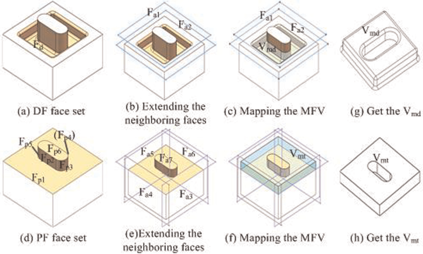
Flowchart of mapping strategy from the intersecting features to the MFV: (a) DF face set, (b) Extending the neighboring faces, (c) Mapping the MFV, (d) PF face set, (e) Extending the neighboring faces, (f) Mapping the MFV, (g) Get the Vmd and (h) Get the Vmt.
Case study
Based on the above-mentioned framework and presented key techniques, a prototype system has been implemented by using the Andy Charleslan’s System (ACIS) as the solid modeler, the Hoops as the display modeler and Visual Studio 2008 as the developing language to construct the WPMs. A large number of machined parts with different types of machining features are tested and analyzed based on the developed system. To demonstrate the proposed basic points, two different machined parts with complex intersecting features are chosen to be tested. The obtained results clearly show the capability of the presentation algorithm.
Illustrative case study 1
The implementation case is presented in detail for the WPMs’ construction of this machined part in machining evolution. The machining sequence of this part is shown in the Figure 3. The three-dimensional B-Rep model of this case is shown in Figure 12(C1). It contains three types of machining feature: DFs (pocket, slot and hole), PFs (boss) and transition features (chamfer). There are two types of intersecting features: two pockets intersecting together and a boss intersecting with a slot. Figure 12 shows the detailed processes of how to generate WPMs in the machining stages.
WPM-V. Select a pocket face as the seed face. The pocket faces and its neighboring faces are searched based on the proposed methods in section “Recognizing the DF faces.” The other pocket of this part is obtained. They are displayed in Figure 12(A6). Then, the MFVs are obtained based on the methods which are illustrated in section “The mapping strategy of DF.” The system interface diagram displays the generated WPM-Vas shown in Figure 12(C2).
WPM-IV. The generation process of WPM-Vis similar to the WPM-VI. The system interface diagram of generating the WPM-II is shown in Figure 12(C3).
WPM-III. The height of boss is equal to the height of slot wall. Therefore, this intersecting feature is seen as the DF to be dealt with. The contained chamfer is seen as the subsidiary feature, and it does not need a separate treatment. A slot face is selected as the seed face, the slot feature faces are obtained based on the approach supplied in section “Recognizing the DF faces” (see Figure 12(A4)). Figure 12(C4) shows the generated WPM-III with the system interface diagram.
WPM-II. One hole face is obtained and the same hole face is searched as shown in Figure 12(A3). Their corresponding MFVs are shown in Figure 12(B4).
WPM-I. A slot is formed in this machining stage. The approaches of obtaining feature faces and forming the corresponding MFV are provided in sections “Recognizing the DF faces” and “The mapping strategy of DF.” The generated WPM is displayed in Figure 12(C6).
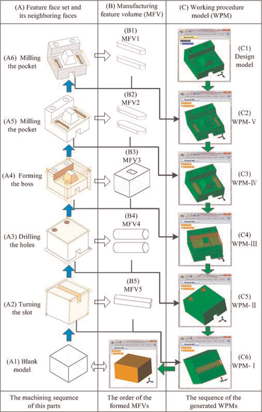
Constructing the WPMs of the machined part in the developed prototype system: (a) feature face set and its neighboring faces, (b) manufacturing feature volume and (c) working procedure model (WPM).
Illustrative case study 2
This illustrative case study is a complex prismatic part as shown in Figure 13, which is taken from the literature. 15 This prismatic part contains lots of interesting features, which are intersected by the DF and the PF. Based on the provided functions of the developed prototype system, the processes of obtaining machining feature faces and forming MFVs are shown in Figure 13(a) and (b), respectively. The recognized machining feature faces are shown with the yellow color in the left of each interface diagram and the face information is shown in the right of each interface diagram. All the MFVs of this prismatic part are indicated with transparent colors as shown in Figure 13(c).
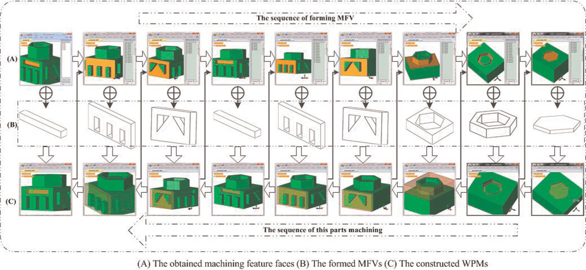
Flowchart of forming the MFVs and constructing the WPMs: (a) the obtained machining feature faces, (b) the formed MFVs and (c) the constructed WPMs.
According to the proposed algorithm, the machining feature faces are recognized by the selected machining feature. The MFVs are formed by using the provided method of section “Forming the MFV.” The WPMs are constructed by combining the formed MFVs with the machined part model.
Conclusion and future work
In this article, a new method to construct the three-dimensional WPMs for the dynamic evolution of the machined parts has introduced. Mapping the machining feature to its MFV is a critical factor in this proposed method. In order to get the MFVs expediently, a strategy of mapping the machining features to MFVs is proposed. The mapping strategy is performed in the following steps. In the first step, the edges and neighboring faces of the seed face are researched based on the selected seed face by the process planner. In order to recognize the machining feature faces, the geometric reasoning rules are formulated based on the topological relations of the machining features. In the second step, applied a closure to the machining feature faces, the MFV is formed by applying additional neighboring faces and their extensions. Finally, the WPM is generated by combining the obtained MFV with the finished part.
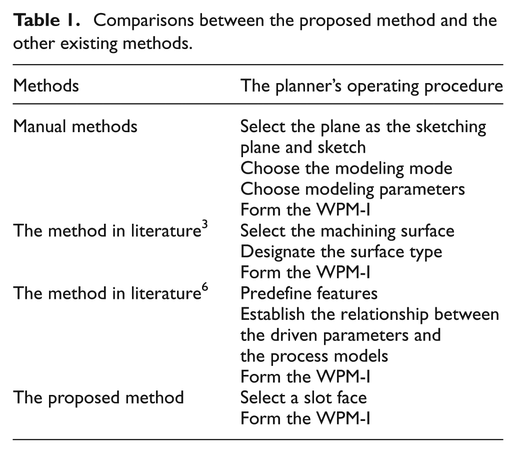
For the purpose of demonstrating the efficiency of the proposed method, we take the forming process of the WPM-I (as shown in Figure 12) as the example to explain the comparisons between the proposed method and the other existing methods listed in Table 1. These existing WPM construction methods can be applied in the three-dimensional manufacturing environment. When constructing the WPM, the planner can only select one machining face based on the proposed method in this article. Therefore, the efficiency of the process planning can be improved.
Comparisons between the proposed method and the other existing methods.
According to the feature recognition technology, the generation ideas and methodology of the WPM are proposed, which can shorten the modeling time and meet the planner’s custom by the comparisons. Some benefits of the proposed approach are described as follows:
Save the construction time of the WPMs. This proposed method avoids the unnecessary conversion from the two-dimensional drawing to three-dimensional model.
More direct and customary for planner. When forming the WPMs, the planner does not convert the process knowledge to the corresponding modeling knowledge.
Simulate the machining process. The constructed WPMs can dynamically and visually display the changes on geometric shapes and manufacturing information in each process.
The results obtained from the case study section clearly show the capability of the developed algorithms. Now, the developed algorithm as a module has been applied in the developed prototype CAPP system. The constructed WPMs can be used in other digital manufacturing processes, such as evaluating the generated process route by a visualized display, measuring the manufacturing information of the key process and designing the fixtures.
In general, the construction techniques and principles of the WPMs can be extended to other type parts. More efforts should be made to realize this expansion. The major challenges and possible solving ways could be summarized as follows and these will be the focus and direction of our future research.
The geometric reasoning rules of identifying the machining feature faces. This article only concerns the planar and its extension face, without considering the other types of face such as the curved surfaces, so the proposed recognition methods of the machining feature faces should be further extended.
The mapping strategy of the MFV. The proposed strategy only focuses on the machined parts, which are generated by removing the material volume in machining, but does not concern other parts which do not change the material volume in machining such as the sheet metal processing. So, the proposed mapping strategy needs further modification and creation.
As original work, this research primarily concerns the construction of the WPM for machining process planning. For most machined parts, the proposed method can work very well, but there are still some limitations. When the parts include freeform surfaces such as the spiral bevel gear and the impeller blades, it is necessary to find a new algorithm to map the MFV from the freeform surface.
Footnotes
Declaration of conflicting interests
The author(s) declared no potential conflicts of interest with respect to the research, authorship, and/or publication of this article.
Funding
The author(s) disclosed receipt of the following financial support for the research, authorship, and/or publication of this article: This work is funded by Certain Ministry of China under Grant Numbers 51318010103, 51318010102.