
Abstract
Undesirable vibrations that occurred in cold rolling mills, widely known as chatter, are studied in this article by considering the interaction of three types of vibrations, namely, the longitudinal vibration of the rolled strip and the torsional and vertical vibrations of the upper work roll. The dynamic component of rolling force is determined using the quasi-static model under the assumption that the changes in roll gap and strip tension produce the variation of rolling force. The coupled vibrations of the work roll and rolled strip are mathematically governed by a set of 3-degree-of-freedom non-linear equations. Under chatter conditions, a new variable is introduced to represent the motion of the quasi-neutral point. A stability criterion for the motion of the quasi-neutral point is developed by studying the eigenvalues of the corresponding characteristic equation of the linearized parts of the non-linear equations. The chatter stability can then be examined by evaluating the determinants of five matrices. Numerical examples are given to show the stable and unstable vibrations in the cold rolling process. The unstable vibration would lead to skidding phenomenon and even break the rolled strip. The results presented in this article provide new insights into the dynamic interaction of the coupled vibrations and the dynamics of the rolling process.
Introduction
Undesirable severe vibrations that occurred in cold rolling mills, generally referred to as chatter, have been one of the main concerns to mill operators. Excessive chatter may not only result in unacceptable gauge variations in strip thickness and chatter marks on strip surface but may also lead to a damage to mill components (such as backup rolls) and to undesirable operating conditions (such as high noise levels) for mill crews. For the vibrations of the work and backup rolls, basically there are three predominant types of oscillations in cold rolling mills, which are known as the torsional, third-octave-mode and fifth-octave-mode chatter in the literature. The corresponding resonant frequencies of these oscillations are approximately between 5 and 15 Hz for the torsional mode, 125 and 240 Hz for the third-octave mode, and 550 and 650 Hz for the fifth-octave mode. Roberts 1 noted that the actual resonant frequencies pertaining to a mill stand are directly related to the design of the stand such as roll size, screwdown design dimensions of the mill housing and so on.
Chatter has been an active topic in the literature of cold rolling process. Yun et al. 2 conducted a comprehensive review of the modelling of stand structure and rolling process for cold rolling. In studying the vertical vibration (which is regarded as the third-octave-mode and fifth-octave-mode chatter in the literature), the mill stand is typically modelled by a linear lumped parameter system with all the masses vibrating in the same direction and often assumed to be symmetrical with respect to the strip surface, which leads to a reduction in the number of degree of freedom by a factor of 2. In developing the roll gap model, Yun et al. 2 , and Ginzburg and Ballas 3 noticed that the resultant rolling force obtained from the rigorous modelling of the rolling process is strongly non-linear in nature and expressed approximately by the first-order terms in the Taylor series expansion when carrying out numerical simulations. To overcome the analytical intractability of the rolling force, a quasi-static model has been introduced to simplify the dynamics of the rolling process. The quasi-static model assumes that the variations in roll gap and vibrations engaged in the rolling process produce variations in rolling force, which are similar to those occurring under steady-state rolling conditions. It is widely believed that chatter is an action–reaction dynamic phenomenon in the sense that vibrations can lead to variations in roll gap and roll speed, which, in turn, result in further variations in the dynamic rolling force.
The existing research on the rolling chatter has focused on understanding the chatter phenomena and determining the stability conditions. For example, Gregorczyk 4 developed a mathematical model of a continuous rolling mill by considering the vertical vibration of roll stand, torsional vibration of rolling mill drives and roll gap dynamics. Hu and Ehmann 5 combined a linearized rolling process model and a structural dynamic model to study the fifth-octave-mode chatter. Meehan 6 utilized a discrete spring–mass–damper system to study the vertical vibration of a four-high stand and examined the instability of the third-octave-mode chatter. Swiatoniowski and Bar 7 simplified the transverse vibration of the strip linking two stands to a 1-degree-of-freedom non-linear equation. Kimura et al. 8 studied the effects of rolling speed and frictional coefficient on the stability of mill vibration and showed that the mill vibration tends to be self-excited with an increase in rolling speed. Lin et al. 9 presented a non-linear model describing the dynamic interaction between work rolls and metal sheets and studied the instability of strip rolling. Bar and Bar 10 derived 2-degree-of-freedom non-linear equations to study the vertical vibration of a rolling stand and the transverse vibration of the strip. Nizoil and Swiatoniowski 11 studied the vertical vibrations of rolling mills and their negative effect on the sheet quality. Hu et al. 12 examined the third-octave-mode chatter and its stability by combining a structural dynamics model and a linearized rolling process model.
Later, Brusa et al. 13 investigated the dynamic behaviour of a Sendzimir mill and examined the effects of roll unbalance, motor dynamic irregularities and bearing faults. Kim et al. 14 developed a mathematical model of a cold rolling mill by considering the driving system, the frictional forces between the rolls and the stiffness caused by the roller bearings and the contact between rolls. Niroomand et al. 15 used the Arbitrary Lagrangian–Eulerian (ALE) finite element method to simulate the chatter vibrations and compared two main chattering with those of the experimental measurements. Swiatoniowski and Bar 16 developed a model for the self-excited high-frequency vibrations and studied the effects of rolling stand and process parameters on vibrations. Kim et al. 17 considered the stiffness of roller bearings and contact between rolls in their model and studied the vertical and horizontal vibrations of work rolls. Zhao and Ehmann18,19 formulated the state-space models of single- and multi-stand chatter and investigated the negative damping and regenerative effects on the stability of tandem mills. Heidari et al. 20 developed a chatter model of the cold strip rolling by considering unsteady lubrication and studied the effect of rolling lubricant on the chatter critical speed.
The chatter phenomenon in a cold rolling mill can be considered as a complicated coupling between the roll stand chatter and the strip vibration, following the understanding of the vertical vibrations of the work and backup rolls. As Johnson and Qi 21 suggested, the interaction between the work roll and the rolled strip must be considered in order to develop an in-depth understanding of rolling chatter instability. The dynamic interaction between the work rolls and the metal sheet was studied by considering the transverse vibration of the strip coupled with the vertical vibration of the roll stand 7 and incorporating a work roll sub-model and a metal sheet roll-bite sub-model. 9 From a perspective different from the existing studies, this article considers the dynamic interaction of three types of vibrations, namely, the longitudinal vibration of the rolled strip and the torsional and vertical vibrations of the work roll. It should be noted that chatter vibrations can also occur in other manufacturing process including milling and grinding operations.22–27
In strip rolling, the location of neutral plane is very important in that it governs the condition of the cold rolling process. Ideally, the neutral plane does not move along the arc of the roll contact if no vibration is involved in the rolling process. In the presence of rolling chatter, the position of neutral plane may vary along the arc, either on or outside the arc of the roll contact. Thus, an important technical issue needed to be addressed is under what conditions the neutral plane remains on the arc of the roll contact. This research issue has prominent practical relevance to ensuring a stable rolling operation.
This article aims to study the stability of the coupled vibrations. This article is organized into six sections. The details on the modelling of the coupled vibrations are developed in section ‘The modelling of the coupled vibrations’. The dynamic component of the rolling force is analytically obtained in section ‘Dynamic component of the rolling force’. Section ‘Stability of the coupled vibrations’ presents the stability analysis for the coupled vibrations by introducing a new variable. The numerical results are discussed in section ‘Numerical examples’, and finally section ‘Conclusion’ is given.
Modelling of the coupled vibrations
In order to study the dynamic interaction of the coupled vibrations, the mathematical models to be developed in this article include the vertical and torsional vibrations of the upper work roll, the longitudinal vibration of the rolled strip and the dynamic component of the rolling force. Assumptions will be made to simplify the modelling of vibrations in this section, and the equations of motion governing the coupled vibrations will be derived by applying Newton’s second law of motion.
Assumptions and simplifications
Chatter vibrations in cold rolling mills are a complex dynamic problem and remain not fully understood, to the author’s best knowledge. In order to overcome the theoretical intractability of chatter phenomenon, the assumptions and simplifications to be made in this article are given below:
It is assumed that the work roll experiences vertical and torsional vibrations only and its horizontal vibration is ignored.
The lower and upper parts of a roll stand are assumed to be symmetrical with reference to the roll gap. The dynamic conditions of both parts of a roll stand are considered to be identical. Consequently, only the upper work roll will be considered in subsequent analysis. Then, the roll stand can be approximately simplified to be a two-high stand, as shown in Figure 1(a).
The backup roll is lumped with the stand and bearings. Their collective effect on the work roll is represented by linear stiffness
The resultant frictional force and rolling force acting in the roll bite are assumed to apply in the middle of the arc of roll contact. As shown in Ginzburg and Ballas, 3 the resultant frictional force can be considered to be proportional to the rolling force that is perpendicular to the strip surface.
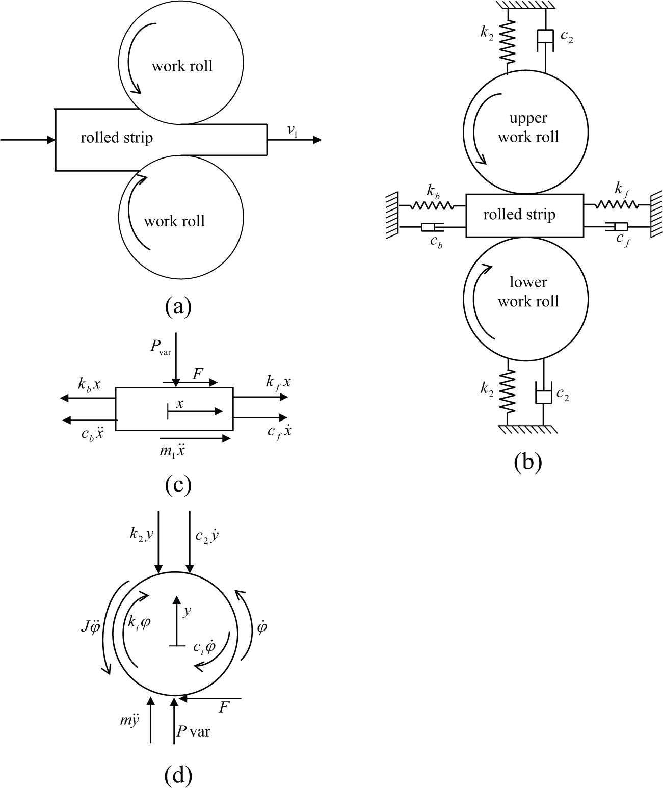
Dynamic modelling of the work roll and rolled strip: (a) simplified schematic diagram of a single two-high stand, (b) modelling of the work roll and strip segment as a lumped mass–spring–damper system, (c) free-body diagram of the strip segment and (d) free-body diagram of the upper work roll.
Equations of motion governing the coupled vibrations
Under the assumptions made in section ‘Assumptions and simplifications’, the structural dynamics of the mill stand can be modelled as a linear lumped parameter system with the upper work roll vibrating in vertical and torsional directions, and the dynamics of the rolled strip modelled as a mass–spring–damper system with the lumped mass vibrating in the horizontal direction, as shown in Figure 1(b). For simplification, the strip back and forward tensions are expressed by the corresponding equivalent back and front stiffness
Under steady-state normal rolling operation without vibrations engaged, the whole system is in the equilibrium state of static balance conditions including the normal rolling force and the frictional force. This is an ideal situation that may be rarely observed in industry. Once vibrations begin, the main source of excitation for vibrations comes from the variable part of the normal rolling force, while the corresponding static part is on the balance with its counterpart relevant to the initial conditions. Accordingly, it is the variable part of the frictional force that induces the torsional vibration of the upper work roll and the longitudinal vibration of the rolled strip. It should be noted that the vibrations can in turn change the variable component of the normal rolling force and then the variable part of the frictional force. For the horizontal vibration of the rolled strip, an application of Newton’s second law of motion leads to a second-order differential equation of the form

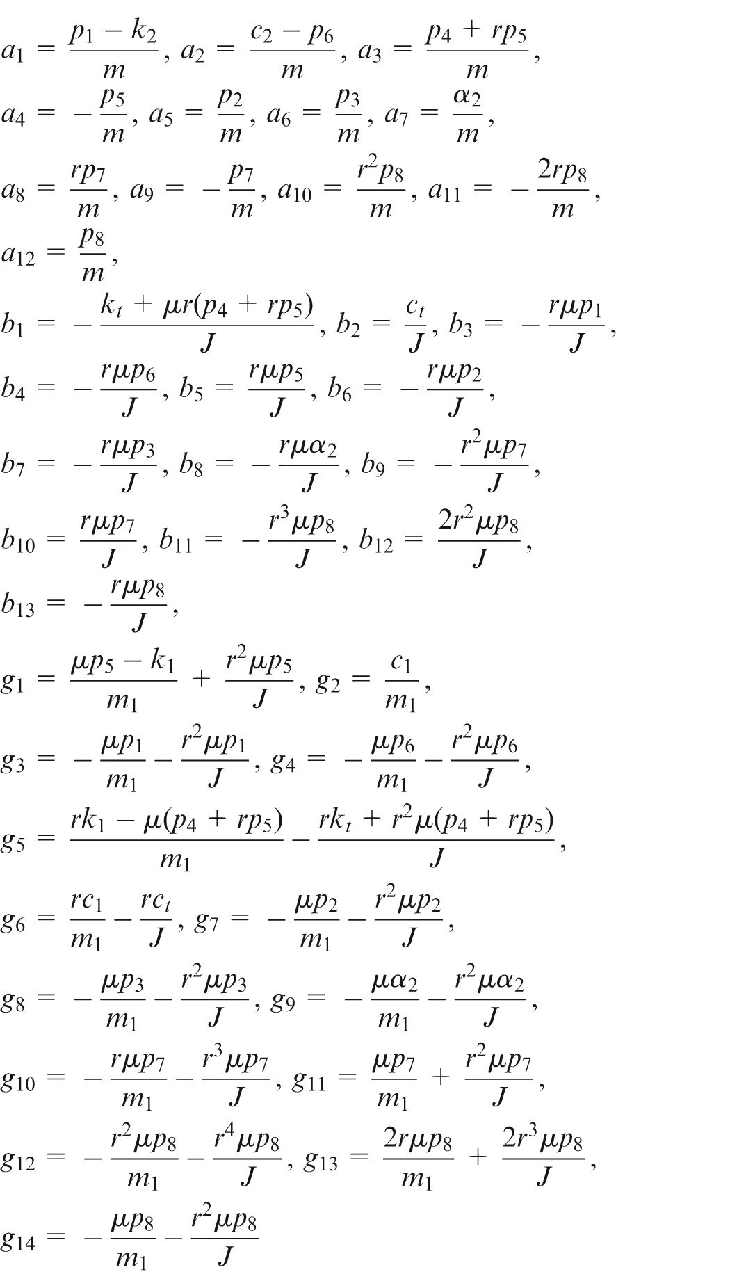
where
The torsional and vertical vibrations of the work roll are considered while the horizontal vibration is ignored in this article but will be pursued in the future. The symmetry assumption of the mill stand made in section ‘Assumptions and simplifications’ renders the vibration analysis of the two-high stand by considering one work roll only. The free-body diagram of the upper work roll is shown in Figure 1(d), where

where m is the lumped mass of the upper work roll, k
2 represents the stiffness resulting from the contact with backup roll and bearings,
For the torsional vibration of the work roll, the equation of motion can be written as

where J is the mass moment of inertia of the work roll,

where
Dynamic component of the rolling force
A number of different models for rolling force and roll torque have been developed over the past decades. Roberts
1
, Yun et al.,
2
and Ginzburg and Ballas
3
summarized several models developed in their text books and literature review article. Two of the widely used modelling methods are the slab analysis and the quasi-static model of the rolling process. The slab method is applicable to the steady-state rolling process only as it does not consider the dynamics of the rolling process induced by the vibrations of work rolls. A quasi-static model can incorporate the dynamics of the rolling process into the rolling models. Essentially, the quasi-static model method assumes that the dynamic component of the rolling force depends on the dynamic variations in roll gap and strip tension. Tlusty et al.
28
developed the dynamic model of the rolling force that consists of three variable components due to the variations of both strip tension and contact length. However, they assumed that the vertical vibration of sinusoidal function form is known beforehand in formulating the variable rolling force. Then they studied the vibrations of the work roll excited by the dynamic component of the rolling force. On the contrary, in this article, the coupled vibrations of the work roll and strip are assumed to be unknown before determining the variable rolling force using a quasi-static model. This assumption is more rational for studying the chatter problem because the vibrations engaged in the work rolls and strip will affect the rolling force exerting on the work roll and strip, and vice visa. Figure 2 shows a schematic of a rolled strip in a simple two-stand cold rolling mill for developing the quasi-static model. It is assumed that a strip of width
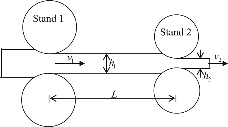
Schematic of a two-stand quasi-static model of the rolling process.
The dynamic component of the rolling force is assumed to have four parts

where
As suggested by Tlusty et al., 28 and Swiatoniowski and Bar, 7 the dynamic component of the rolling force due to the vertical vibration of the work roll can be expressed as

where
It should be noted that even in the presence of vibrations, the amplitude of the vertical vibration of the work roll is in practice far less than the thickness reduction of the strip, that is,
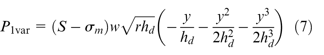
Equation (7) indicates that the first dynamic component of the rolling force is a non-linear function of the displacement of the vertical vibration of the work roll.
The contributions of the other two types of vibrations to the dynamic component of the rolling force will be studied by adopting some ideas introduced by Tlusty et al.
28
and Yun et al.
2
As shown in Figure 2, both the entry thickness

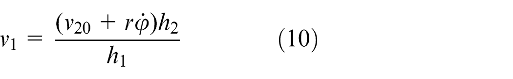
The exit speed

Here, the longitudinal vibration of the rolled strip is ignored at this stage, and its contribution to the interstand tension will be discussed in the component
If no torsional vibration happens, the nominal exit speed, denoted by
It is shown that the entry speed of the strip has a mean and variable component. It follows correspondingly that the variable entry speed is given by
where
The variable entry speed
where
Since the neutral point has been assumed to be at the exit of the roll bite, the contribution from the variable strip tension at the exit of Stand 2 to the dynamic component of the rolling force is negligible and thus ignored here. The stretch of the rolled strip produces a variable strip tension at the entry of Stand 2. The variation of the tension stress is given by
where
The dynamic component of the rolling force due to the variable interstand tension can be obtained by borrowing the formulation given by Tlusty et al. 28 and expressed as
The dynamic component
The presence of the vertical vibration of the work roll and the longitudinal vibration of the rolled strip produces the variation of the contact length at the exit of the strip. During an instant
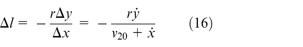
where the negative sign indicates the shortness of the contact length.
The dynamic component
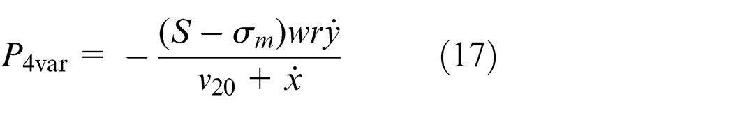
Applying Taylor series expansion about the nominal speed
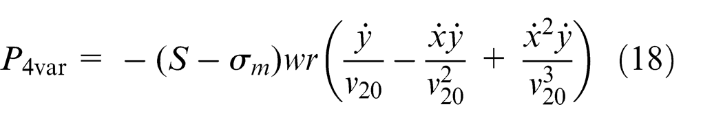
Here, only the first three terms are kept in the series.
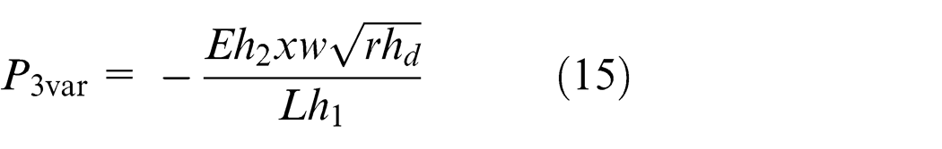
Substituting equations (7), (14), (15) and (18) into equation (5) leads to the resultant dynamic component of the rolling force
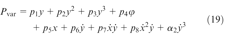
where
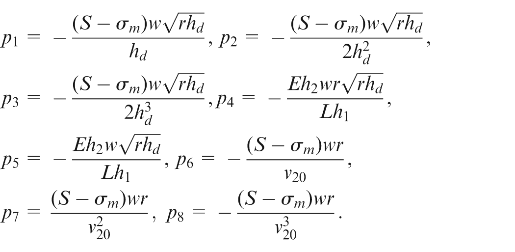
The term
Stability of the coupled vibrations
The dynamic behaviour of rolling chatter can be examined by studying equations (1)–(3). These three equations will be rewritten by introducing a new variable in section ‘Introduction of a new variable’. The stability of the coupled vibrations will then be examined in section ‘Stability analysis’.
It is known that the neutral plane (point) plays an important role in strip rolling. As discussed by Yuen et al., 30 when the neutral plane is at or beyond the roll-bite exit, there is not enough traction to pull the strip through the roll bite. This phenomenon is known as skidding. When the neutral plane is at or ahead of the roll-bite entry, the strip is drawn through the roll bite and moves faster than the roll throughout the entire contact region. This phenomenon, although rare, may occur under certain cold rolling conditions and is known as slipping. During the steady-state rolling process, the neutral plane is at a certain point on the arc of the roll contact. Ideally, the neutral plane does not move along the arc of contact if no vibration is involved. Practically, in the presence of rolling chatter, the neutral plane may either stay at or move forward and backward about its original position. A larger vibrational velocity of either work roll or strip has the potential to move the neutral plane out of the arc of contact.
Introduction of a new variable
In section ‘The modelling of the coupled vibrations’, the origin of the longitudinal displacement of the rolled strip and the torsional displacement of the upper work roll is assumed to be at the location of the neutral plane for the rolling operation without vibrations occurring. This origin will be referred to here as the original neutral plane (point). For the purpose of comparison, the neutral plane for the rolling operation involving vibrations will be referred to here as the quasi-neutral point. The vibrations of the work roll and strip can cause the quasi-neutral point moving forward and backward about the position of the original neutral plane, towards either the entry side or the exit side of the roll bite. The new position of the quasi-neutral plane is at best indicated by the displacement of motion from its origin. It is thus meaningful to introduce a new variable to represent the movement of the quasi-neutral plane in the rolling process. This new parameter can easily track the motion of the quasi-neutral point along the arc of roll contact.
When vibrations occur in the rolling process, the peripheral velocity of the work roll is given by

where
The surface velocity of the rolled strip in the presence of longitudinal vibration is

where
The velocity of the quasi-neutral point is the difference of the peripheral velocity and the strip velocity that are given by equations (20) and (21)

The first term vanishes under normal rolling conditions without vibrations engaged. The second term is related to the torsional vibration of the work roll and the longitudinal vibration of the rolled strip. The velocity of the quasi-neutral point is then expressed as

In the presence of vibrations, the speed of the quasi-neutral point may not be equal to 0. Only if the kinematic relation
A new variable
where
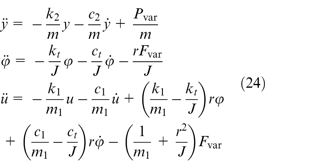
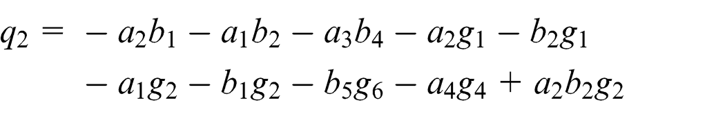
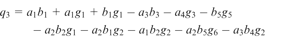
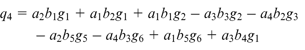
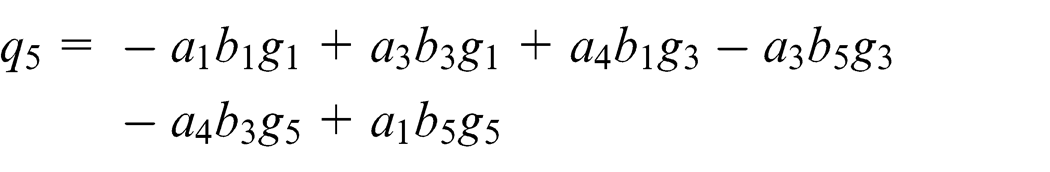
Substituting equations (4) and (19) into equation (24) and simplifying the resultant equations yield
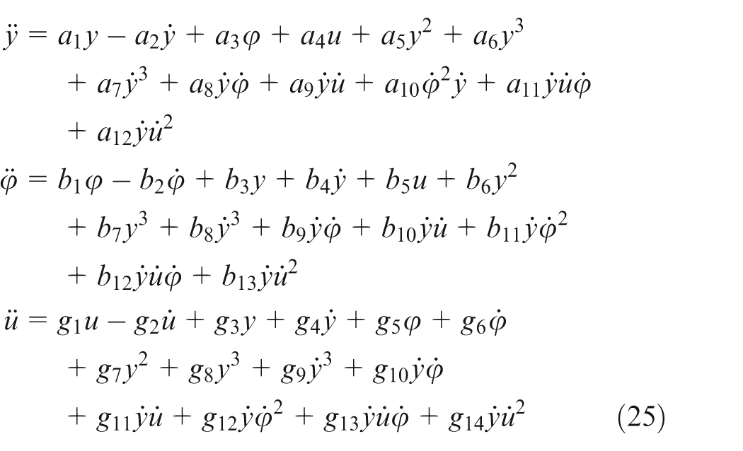
where
Here, the variable
Stability analysis
In order to study the stability and later perform numerical integration, the three second-order coupled differential equations given by equation (25) should be rewritten as a system of the first-order coupled differential equations. This can be achieved by introducing new variables
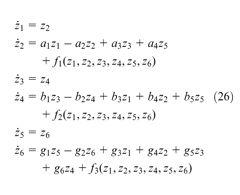
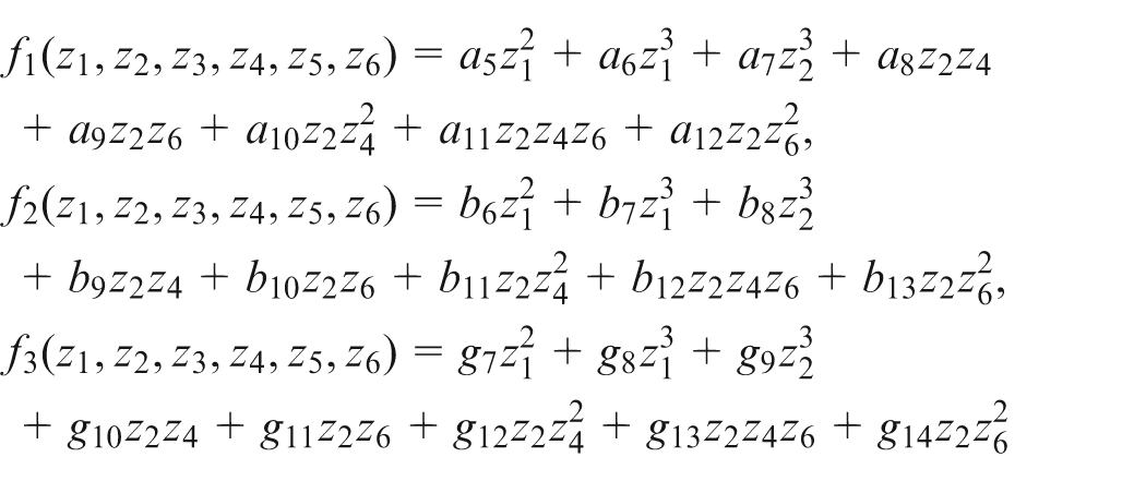
where the non-linear functions
The non-linear system given by equation (26) admits the trivial (zero) solution,
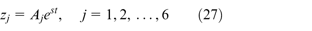
where

where


According to the criterion of Routh-Hurwitz,
32
all roots of the polynomial
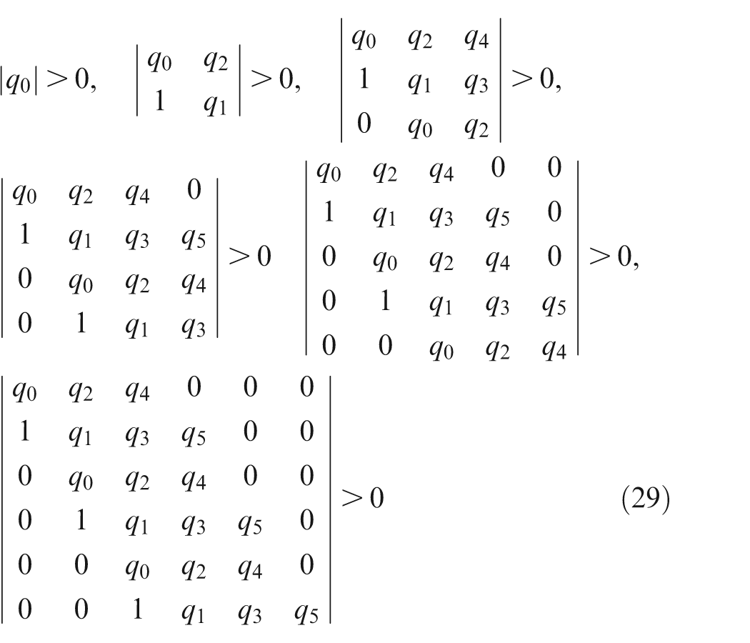
The first determinant simply states that the coefficient
Numerical examples
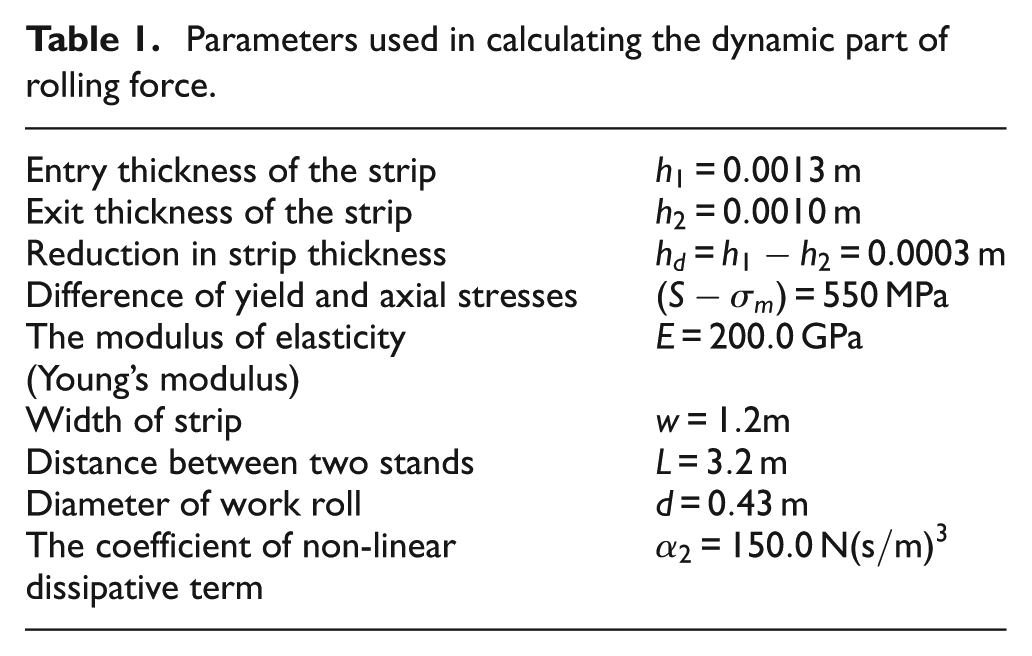
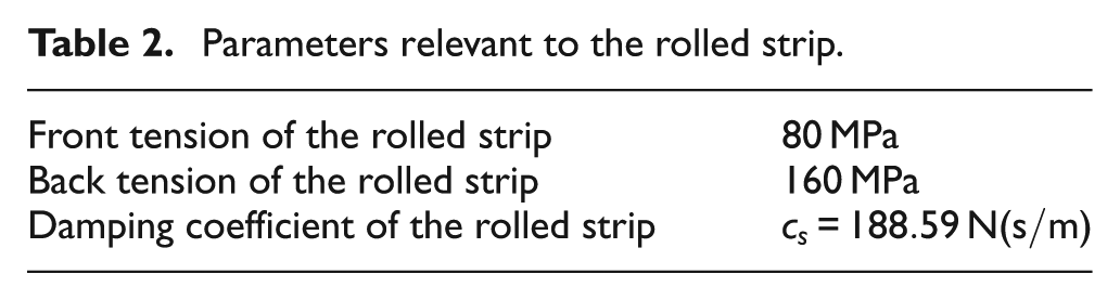
Numerical simulations using MATLAB are carried out to obtain the dynamic behaviour and stability boundary of the coupled vibrations by integrating equation (26) and evaluating the inequality equation (29). The values of system parameters used are given in Appendix 1, unless otherwise specified (Tables 1–3).
Parameters used in calculating the dynamic part of rolling force.
Parameters relevant to the rolled strip.
Parameters related to the work roll.
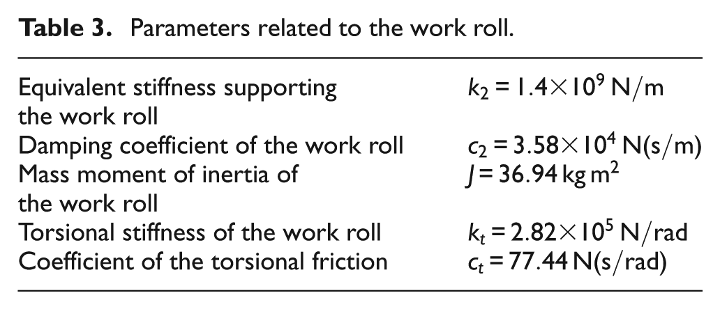
Figure 3(a) shows the variation of the strip front tension with the frictional coefficient
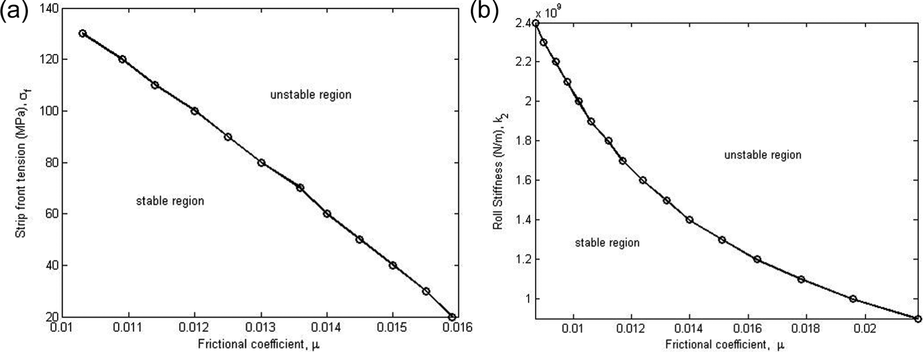
Stability boundary of the coupled vibrations: (a) variation of the front tension with the frictional coefficient and (b) variation of the roll stiffness with the frictional coefficient.
To validate these analytical results, numerical integrations are performed to equation (26). In carrying out numerical integration, the values of system parameters are picked up out of the regions above and below the stability boundary curve as shown in Figure 3(a). The results are illustrated in Figure 4 for two values of the front tension stresses σf = 60 and 210 MPa, respectively. The trivial solution is asymptotically stable when the front tension is less than the critical value and unstable when the front tension is greater than the critical value. As shown in Figure 4(a), the three types of vibrations decrease their amplitudes as time goes and eventually die out in a short period of time. The motion of quasi-neutral point also gradually converges to 0 as time goes, indicating that the quasi-neutral plane remains along the arc of roll contact and rests on its original position. On the contrary, the unstable vibration eventually goes to infinity after some periods of oscillation. As shown in Figure 4(b), the vibrations starting from a very small value of initial conditions increase their amplitudes very quickly. Within t=1.4 s, the amplitudes of the torsional and vertical vibrations increase from the order of
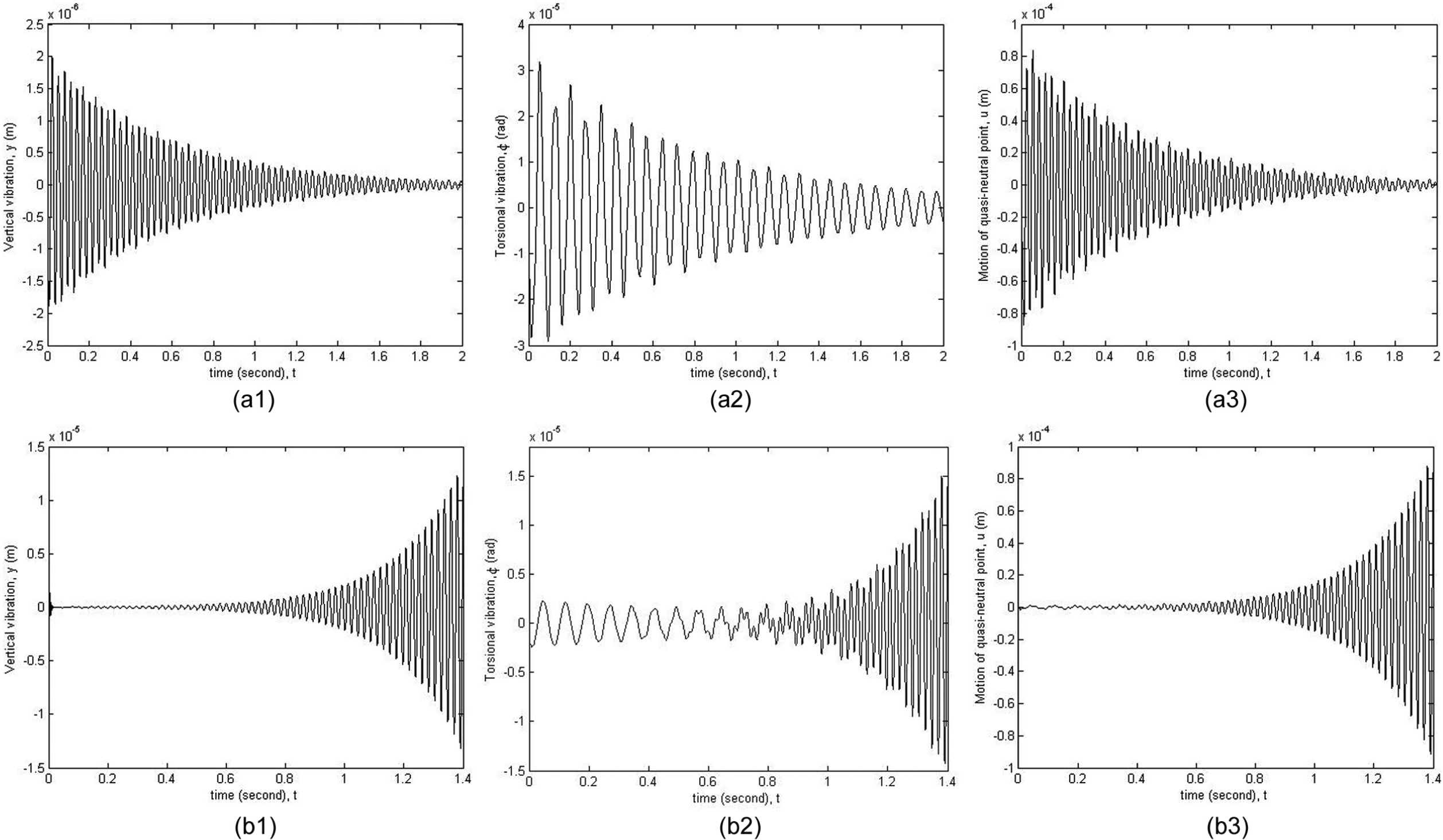
Stable and unstable coupled vibrations: (a) stable vibrations for the front tension stress σ f = 60 MPa and (b) unstable vibrations for the front tension stress σ f = 120 MPa.
The numerical simulations of stability condition (29) also suggest that the stability boundary is strongly dependent on the system parameters. For some combinations of system parameters, the stability boundary curves are different in terms of the curve shapes. It is also found by numerical simulations that the stability of the trivial solution is sensitive to the initial conditions of integration. Different sets of initial values can lead to distinct dynamic behaviour of the system, namely, stable and unstable vibrations. The underlying mechanisms would be the sensitivity of the rolling process on the rolling conditions. From the perspective of dynamic analysis, the dynamic system given by equation (26) is non-linear in nature and may have fractal basin of attraction. This indicates that the stability of rolling operation depends on the initial conditions. For some sets of initial conditions, the rolling chatter is stable, while for others the rolling chatter is unstable even if under the similar set of system parameters. This may be the reason for the fact observed in practice that chatter occurs in the same stand under similar operating conditions on different dates. Specifically, no chatter is observed on one day and chatter happens on another day when rolling the same materials under the nearly same conditions.
Conclusion
A chatter model incorporating the structural dynamics and roll gap dynamics has been developed in order to study the dynamic interactions of the longitudinal vibration of rolled strip and the vertical and torsional vibrations of the work roll. It was shown that these three types of vibrations are strongly coupled in a non-linear manner.
For the rolling process under chatter conditions, a stability criterion was obtained for the motion of the quasi-neutral point. The effects of the frictional coefficient on the stability of the coupled vibrations were studied under variations of the front tension and roll stiffness. A decrease in the forward tension requires increasing the frictional coefficient to ensure a stable rolling operation. A decrease in roll stiffness also requires an increase in the frictional coefficient to ensure the stability of the coupled vibrations. Stable vibrations indicate that the quasi-neutral plane moves towards the original position of the neutral plane and eventually locates at the original position. As a result, the peripheral speed of the work roll and roll surface speed have a tendency to be identical again, although their values may be changed due to vibrations engaged. An unstable vibration grows its amplitude quickly and leads to excessive tension fluctuation if no action is taken. Unstable vibrations imply the occurrence of skidding or slipping phenomena and may eventually damage the roll stand or break the rolled strip. To avoid unstable vibrations, the rolling process should be operated in the stability region. Rolling chatter is a complex dynamic phenomenon. The stability boundary and dynamic behaviour of the coupled vibrations strongly depend on the system parameters and rolling conditions. For some combinations of system parameters, different sets of initial conditions (rolling conditions) can lead to different dynamic behaviour, either stable or unstable vibrations.
Footnotes
Appendix 1
The values of system parameters that are used in numerical simulations are based on a four-stand cold rolling process, which is currently operating in a strip production company. Due to the commercially-in-confidential nature, the values of certain parameters are slightly changed from the industry data. Some data are obtained by performing finite element analysis of the stand and rolling process using the design parameters and operation conditions. For the sake of brevity, the detailed procedure is not reproduced here. The SI units of the system parameters are used here instead of the units that are preferred by the engineers and workers in the production company.
The front and back stiffness can be obtained using formulae
The damping coefficient of the work roll is equivalent to the non-dimensional coefficient of damping
Declaration of conflicting interest
The author(s) declared no potential conflicts of interest with respect to the research, authorship, and/or publication of this article.
Funding
The author(s) received no financial support for the research, authorship, and/or publication of this article.