
Abstract
Electrochemical honing is a hybrid finishing process combining advantages and simultaneously overcoming the individual limitations of electrochemical machining and mechanical honing. Finishing of conical gears by electrochemical honing is very complicated due their complex geometry. This article reports on the development of an innovative experimental setup and investigations on improving surface finish of straight bevel gears by electrochemical honing and its process productivity. A novel idea of using twin-complementary cathode gears was envisaged to ensure simultaneous fine finishing of all the teeth of straight bevel gear made of 20MnCr5 alloy steel. Effects of five important electrochemical honing parameters, namely, concentration, temperature and flow rate of electrolyte, rotary speed of workpiece gear, voltage on surface finish and material removal rate of the bevel gear were investigated. Improvement in the microstructure of electrochemical honing finished gear was studied using scanning electron microscopic images. To prove importance of hybridization in improving finishing capabilities of electrochemical honing, a comparative study of surface quality of a bevel gear finished by mechanical honing, electrochemical machining and electrochemical honing was done. The results revealed considerable improvements in the surface quality of the bevel gears finished by electrochemical honing. Electrolyte concentration of 7.5%, temperature of 32 °C, flow rate of 30 L/min, 8 V as voltage and speed of 40 r/min of the workpiece gear yielded the best combination of percentage improvements in average surface roughness (i.e. 58.5%), maximum surface roughness (i.e. 44.4%) and volumetric material removal rate (0.21 mm3/s). This work helps to establish electrochemical honing as a viable alternative bevel gear finishing process which has potential to overcome the limitations of conventional bevel gear finishing processes.
Introduction
Conical gears are used for transmitting power and/or motion between the intersecting shafts (i.e. straight and spiral bevel gears) or the nonparallel nonintersecting shafts (i.e. hypoid gears). Among these, straight and spiral bevel gears are extensively used in the automobiles, aerospace, marine, machine tools, construction machinery, wind turbine, equipment used in the process, cement, steel, oil and gas industries, and so on. The operating performance, service life, power transmission efficiency and noise and vibrations of a gear depend on its surface finish and geometric accuracy. Most of the gears are finished to remove their surface irregularities generated during the teeth cutting operation and to correct their geometric errors. Davis 1 mentions that the different modes of gear failure, namely, pitting, micro-pitting, adhesive wear, abrasive wear and scuffing, can be prevented by improving the surface finish of the gear tooth. Finishing of the bevel gears is very challenging and difficult due to complex geometry of their teeth. Gear grinding and lapping are the most commonly used conventional processes for finishing the bevel gears. But these processes have some inherent limitations. Gear grinding is expensive in terms of initial investments and regular maintenance of the grinding wheels. It requires highly skilled labor. Also, form grinding by a single formed wheel (or two single formed wheels) is time-consuming. Moreover, Karpuschewski et al. 2 highlight that gear grinding can also lead to undesirable effects such as (1) transverse grind lines on the finished surface which cause noise and vibration of the gears and (2) grinding burns which damage the surface integrity of the ground gears and can sometime lead to even gear failure through tooth breakage. Gear lapping is a very slow finishing process which finishes gears in a conjugate pair. It can rectify only minute deviations from the desired gear tooth profile. Moreover, longer lapping cycle may affect the tooth flank profile and thus require extensive care during the operation.
Electrochemical honing (ECH) is a hybrid fine finishing process which combines capabilities of electrochemical machining (ECM) and honing and at the same time overcomes their individual limitations. 3 Major limitation of ECM is passivation of anodic workpiece surface by metal oxides formed due to evolution of oxygen gas at anode during its electrolytic dissolution. This passivation prohibits further electrolytic dissolution of workpiece. Major limitations of mechanical honing include reduced tool life, slow process, incapability of finishing a hardened gear and possibility of mechanical damage to the workpiece (i.e. micro-cracks, hardness alternation and plastic deformation). ECH combines the capabilities of ECM (i.e. capability to machine material of any hardness, production of stress-free surface and higher material removal rate (MRR)) with the capabilities of honing (e.g. correction of geometric errors and controlled generation of functional surfaces). This makes ECH as an ideal choice to explore for alternative superior process for gear finishing. ECH has capability of producing surface finish up to 50 nm with extra care, and simultaneously, it can significantly reduce the geometric inaccuracy of the gears. 3
Jain et al. 3 comprehensively reviewed the past work done on finishing of internal cylinders and gears using ECH. Capello and Bertoglio 4 first time explored use of ECH for finishing the hardened helical gear of involute profile using a specially designed helical gear as the cathode tool. They used voltage in the range of 10–15 V, NaNO3 as electrolyte and an inter-electrode gap (IEG) of 0.4 mm. Their results were not good in terms of the improvement in profile of the finished gear, but it confirmed the possible use of ECH for finishing the gears. Chen et al. 5 developed an experimental setup for finishing the spur gears by ECH and reported improvement in the surface finish, teeth profile accuracy and reduction in noise level. He et al. 6 used slow-scanning field controlled (SSFC) ECH as the time-control method to correct profile errors of the spur gears. Yi et al. 7 used electrochemical tooth-profile modification for the carburized hypoid gears on real-time control basis and developed artificial neural network (ANN)-based model. They mentioned that the gear tooth-profile modification is one of the methods for improving the load-carrying capacity of the gears. Naik et al. 8 used ECH for finishing the spur gears made of EN8 material using different combinations of NaNO3 and NaCl and reported up to 80% and 67% improvement in average surface roughness and maximum surface roughness values, respectively. Misra et al. 9 used ECH for finishing the helical gears made of EN8 and investigated the effects of voltage, electrolyte concentration and rotary speed of the workpiece gear on surface finish using an aqueous solution of NaCl and NaNO3 in a ratio of 3:1 as electrolyte. They reported that electrolyte concentration and voltage have more significant effects on ECH process performance. Pang et al. 10 had used pulse electrochemical finishing for finishing the cylindrical gears using the scanning cathode; they reported improvement in tooth surface finish from Ra value 3.9 to 0.35 μm, and modification in tooth profile is achieved using an uneven IEG, and profile–lead modification can be achieved using a variable moving cathode tool. Ning et al. 11 used pulsed electrochemical finishing (PECF) to finish only one tooth of a spiral bevel gear at a time using a cathode cutter and an indexing mechanism. They reported improvements in maximum surface roughness value from 7.13 to 4.32 μm and reduction in maximum tooth spacing index error and total tooth spacing index error. They also developed a mathematical model for material removal and surface roughness and validated it with the experimental results. Misra et al. 12 used pulsed ECH (PECH) for finishing the spur gears and studied the effects of composition and temperature of electrolyte on the surface finish. They reported aqueous solution of 75% NaCl+25% NaNO3 (by weight) as optimum electrolyte composition and 30 °C as optimum electrolyte temperature. Shaikh and Jain 13 had developed theoretical models of MRR and maximum roughness depth (Rz) of the bevel gear finished by ECH and experimentally validated them.
From the review of the past work, it can be concluded that ECH has not been developed for simultaneous fine finishing of bevel gear teeth. This is probably due to the complex conical geometry of the bevel gears which does not allow the reciprocation of the cathode gear which is required to finish its entire face width. This makes development of an experimental setup for finishing the bevel gear by ECH very challenging. This article reports on surface finish enhancement of straight bevel gears by ECH with an objective to develop ECH as a better, productive and economic alternative process for fine finishing of bevel gears. It was done by
Conceiving a novel idea of twin-complementary cathode gears in which workpiece, cathode and honing gears are arranged in such a manner that the entire face width of the bevel gear teeth is finished without giving it reciprocating motion and also maintaining a constant IEG between the workpiece and cathode gears;
Developing an innovative experimental setup based on this concept for simultaneous fine finishing of all the teeth of a straight bevel gear;
Studying the effects of five ECH parameters, namely, concentration, temperature and flow rate of the electrolyte, rotary speed of the workpiece gear, voltage on the surface finish and MRR of the finished gears and studying microstructure of the best finished gears;
Comparative analysis of a gear finished by ECM, honing and ECH to prove importance of hybridization in improving the finishing capabilities of ECH.
Experimental setup
Simultaneous finishing of all the teeth of a gear by ECH requires (1) the workpiece gear to be made as anode and mesh it with a specially designed cathode gear and honing gear simultaneously. The electrolytic dissolution takes places between the anode and cathode gears in the presence of a suitable electrolyte and supply of direct current (DC), whereas the honing gear scraps the passivating metal oxide layer formed on the anodic workpiece gear due to evolution of oxygen; (2) designing the cathode gear in such a way that there is no contact between the electrically conducting portions of the cathode gear with the workpiece gear to avoid short-circuiting between them; and (3) imparting a suitable combination of rotary and reciprocating motion (along the axis of rotation) to the workpiece gear to ensure finishing of the entire face width of all teeth of the workpiece gear.
Reciprocation of a conical gear (i.e. bevel and hypoid gears) along its axis of rotation during its finishing by ECH is not possible due to continuously varying module along its face width. This problem was solved in this work by envisaging a novel concept of using twin-complementary cathode gears and their meshing arrangement with the workpiece and honing gears (Figure 1(a)). It ensured finishing of the entire face width of the bevel gear without requiring reciprocating motion and simultaneously maintained the IEG required for the electrolytic dissolution. In this arrangement, one of the cathode gears (3) has an insulating layer of metalon sandwiched between two conducting layers of copper, whereas the other complementary cathode gear (4) has a conducting layer of copper sandwiched between two insulating layers of metalon. The conducting layer is undercut by 1 mm as compared to the insulating layers to maintain the IEG between the cathode and anode gears which is required for the anodic dissolution by the electrolytic action. The workpiece gear (1), honing gear (2) and cathode gears (3 and 4) are mounted in such a way that their axes of rotation are perpendicular to each other. The photographs of the designed and developed cathode gears are shown in Figure 1(b). The workpiece gear is given rotary motion by the spindle of a drilling machine, while other gears rotate due to tight meshing with it. The electrolyte (5) is supplied to IEG, and a DC voltage is applied across it. The electrolytic dissolution takes place between the workpiece and cathode gears while honing action occurs simultaneously between the workpiece and honing gears. During the electrolytic dissolution process, evolution of oxygen takes place at the anode forming a passivating metal oxide layer on the workpiece gear surface prohibiting its further electrolytic dissolution. The honing gear removes this passivating layer and exposes fresh surface for further finishing by the electrolytic dissolution. This synchronous finishing by electrolytic dissolution and honing results in enhancement in surface quality of the workpiece gear with high productivity.
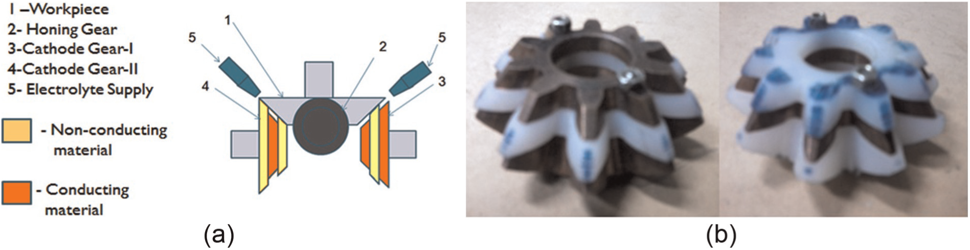
(a) Concept of twin-complementary cathode gear for bevel gear finishing by ECH and (b) photograph of the complementary cathode gears.
An innovative experimental setup for finishing the bevel gears by ECH was designed and developed whose schematic diagram is depicted in Figure 2(a) and its photograph in Figure 2(b). This setup has four subsystems, namely, (1) DC power supply system; (2) electrolyte supply, cleaning and recirculating system; (3) machining chamber housing workpiece, cathode and honing gears; and (4) a machine frame to support the machining chamber and to provide motion to the workpiece gear. DC power supply system had capacity of an output voltage in the range of 0–100 V and current in the range of 10–110 A, and it can be operated either as a constant current source or as a constant voltage source. Positive terminal of the power supply was connected to the stainless steel shaft supporting the workpiece bevel gear, while negative terminal was connected to the two complementary cathode gears through carbon brush and slip ring assembly. The electrolyte supply, cleaning and recirculating system was designed to supply the filtered electrolyte to the machining chamber and recirculate it back to the storage tank. A rotary pump made of stainless steel and capable of developing a wide range of pressures and flow rates was used to supply an aqueous mixture of NaCl and NaNO3 as the electrolyte. Filtration was achieved using two double-stage magnetic and stainless steel mesh filters provided in the electrolyte flow path. Electrolyte pressure and flow rate measuring devices and flow control valve were employed at the pump outlet. The electrolyte temperature was maintained by a heating element fitted with a precise temperature controller. Rotary motion to the workpiece gear is provided by a DC motor fixed on the frame of a drilling machine of 38-mm drilling capacity. This motor has a controller to vary the rotary speed continuously in the range of 30–1500 r/min. The machining chamber, depicted in Figure 2(c), was fabricated using perspex sheets to provide better visualization of the ECH process and better strength-to-weight ratio. Pedestal-type ball bearings were used to mount and support the stainless shafts on which honing and two cathode gears were mounted. Metalon blocks were used to support and mount the bearings due to its corrosion resistance, electrical insulation and higher strength-to-weight ratio. The work-table of the drilling machine (size 400 mm × 400 mm) was used to mount the machining chamber. The workpiece, cathode and honing gears used in this work were the straight bevel gears having 4.83 mm as module. The workpiece gear had 16 teeth, while the cathode and honing gears had 10 teeth each. The most commonly used alloy steel used for commercial applications of the bevel gear (i.e. 20MnCr5 whose composition mentioned in Table 1) was chosen as workpiece and honing gear material. Surface hardness of the workpiece and honing gears were in the range of 50–54 and 58–62 HRC, respectively. All the gears were manufactured on a bevel gear generator based on the Gleason method.
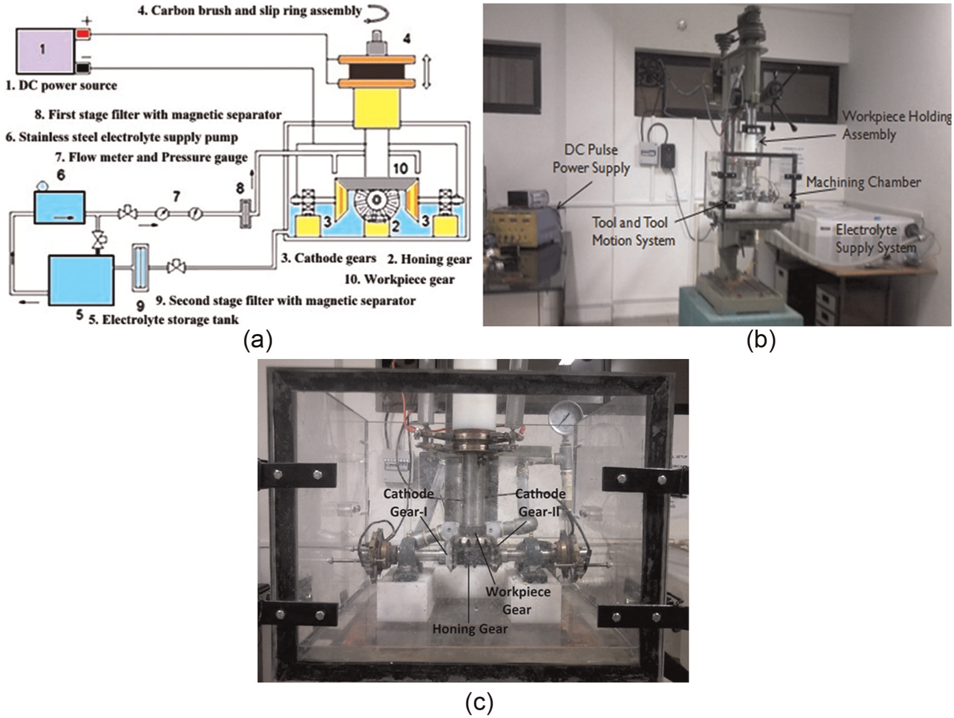
Experimental setup for finishing of straight bevel gears by ECH: (a) schematic diagram, (b) photograph and (c) photograph of machining chamber.
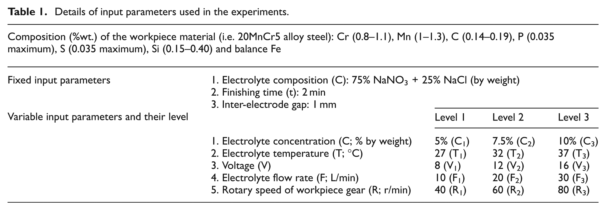
Details of input parameters used in the experiments.
Experimentation
The experimental investigations were planned in different stages, namely, pilot experiments, main experiments and experiments for comparative study of ECM, honing and ECH. The details of experimental methodology are available in Shaikh and Jain. 14 In total, 12 pilot experiments were conducted using full factorial approach to find the optimum electrolyte composition and finishing time. During the pilot experiments, electrolyte composition was varied at four levels (i.e. 100% NaNO3, 50% NaNO3+50% NaCl, 25% NaNO3+75% NaCl and 75% NaNO3+25% NaCl by weight) and finishing time at three levels (i.e. 2, 4 and 6 min) for each electrolyte composition. Electrolyte composition of 75% NaNo3+25% NaCl (by weight) and finishing time of 2 min yielded the best improvements in surface finish. 15 Therefore, this combination was identified as optimum combination for the main experiments.
Different approaches for fractional factorial design of experiments were compared. On the basis of this comparison, Taguchi’s method was selected for the main experiments because it offers advantage such as (1) it gives more reliable estimate of the effects of the variable parameters, (2) it emphasizes on minimizing the effect of noise factors on the responses, (3) it identifies the optimum levels of parameters that optimizes the response through signal-to-noise (S/N) ratio with fewer experiments and (4) it provides insight into effects of interaction among the input process parameters on response which is not available in other methods. 16 Therefore, main experiments were designed and performed according to Taguchi’s L27 (313) orthogonal array to study the effects of electrolyte concentration, electrolyte temperature, electrolyte flow rate, rotary speed of the workpiece gear and voltage on the average and maximum surface roughness (Ra and Rmax) values and MRR. The electrolyte composition, finishing time and IEG were kept constant during these experiments based on the pilot experiment results. Table 1 gives details of fixed and variable parameters used in the experiments.
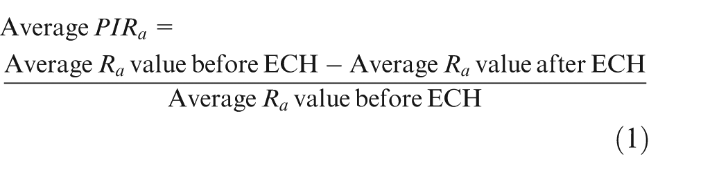
Values of Ra and Rmax were measured before and after finishing by ECH using the contracer-cum-surface roughness tester from KOSAKA, Japan. For analysis of surface roughness parameters, two gear teeth were selected randomly. For each tooth, two measurements, one on left-hand profile and the other on right-hand profile, were done. The arithmetic mean of these four values was used to calculate the average value of concerned parameter. The average percentage improvement in average surface roughness “Ra” values (PIRa) or maximum surface roughness “Rmax” values (PIRmax) was calculated using equation (1). Higher values of average PIRa or average PIRmax indicate the smaller value of final Ra or Rmax
Average value of the volumetric MRR was calculated by dividing the mass loss of the workpiece gear during its finishing by the product of finishing time and density of the workpiece material. The mass of the workpiece gear was measured on a precision weighing balance (Essae-Teraoka Ltd, India) having a least count of 0.01 g.
Results and analysis
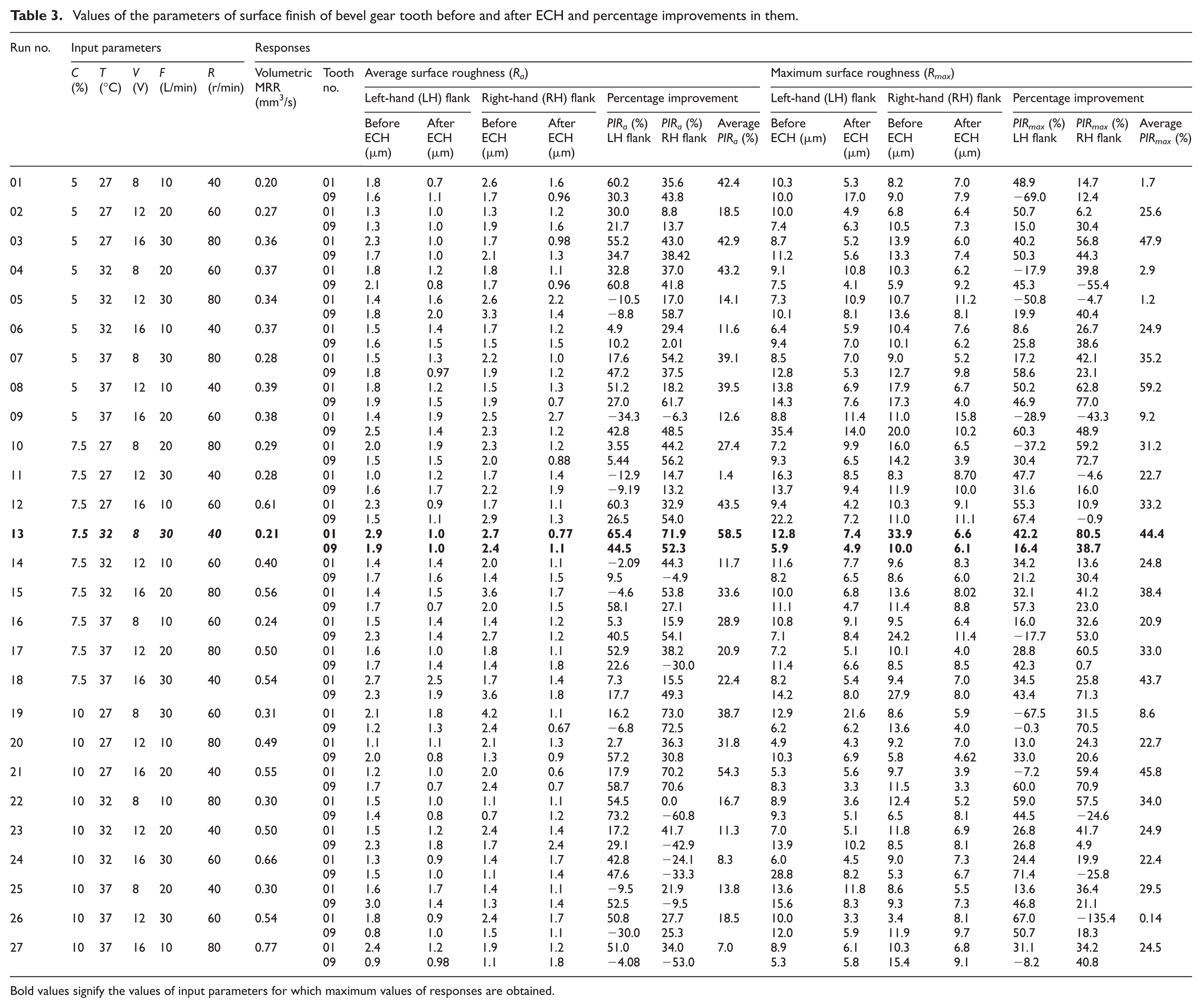
Table 3 presents the experimental results mentioning the values of input parameters and the responses (PIRa, PIRmax and MRR) for the different experimental runs. It can be observed from this table that experiment no. 13 having parametric combination of electrolyte concentration as 7.5%, electrolyte temperature as 32 °C, applied voltage as 8 V, electrolyte flow rate as 30 L/min and rotary speed as 40 r/min yields the maximum value of PIRa (58.54%) and second best value of PIRmax (44.44%).
Figures 3 and 4 graphically depict the variation of average values of PIRa, PIRmax and MRR for different values of the five input parameters. Average value of a response at a particular value of an input parameter was calculated by taking arithmetic mean of all the experimental values of the response at that particular value of the input parameter (i.e. average value of PIRa at electrolyte concentration 5% was calculated by taking average of its values for the experiments from 1 to 9 from Table 3 and so on). It can be seen from Figure 3(a) that middle value of electrolyte concentration, that is, 7.5%, and lower values of electrolyte temperature, that is, 27 °C, resulted in the highest average values of PIRa and PIRmax. Increase in electrolyte temperature leads to more evolution of oxygen at the anode and selective dissolution (for an alloy) which deteriorates surface finish. Figure 3(b) depicts the variation in average values of PIRa and PIRmax with voltage and electrolyte flow rate. It can be seen that electrolyte flow rate does not significantly affect the roughness. The maximum value of average PIRa was observed at lower value of the applied voltage while maximum value of average PIRmax was observed to occur at its higher level. This is due to the fact that at lower values of applied voltage, the higher peaks on the workpiece surface are truncated to a smaller extent along with some material removed from all the other peaks present on the workpiece surface depending upon their distances from the cathode surface resulting in small improvement in PIRmax and more improvement in PIRa, whereas at higher values of applied voltage, the higher peaks on the workpiece surface are truncated by a larger amount with more material removal from all the other peaks as well as valleys present on the workpiece surface resulting in more improvement in PIRmax and small improvement in PIRa. Figure 3(c) depicts the variation of average values of PIRa and PIRmax with the rotary speed of the workpiece gear, and it can be seen that the lower rotary speed provides more exposure to the workpiece surface for electrolytic dissolution to take place resulting in increased value of average PIRa and average PIRmax.
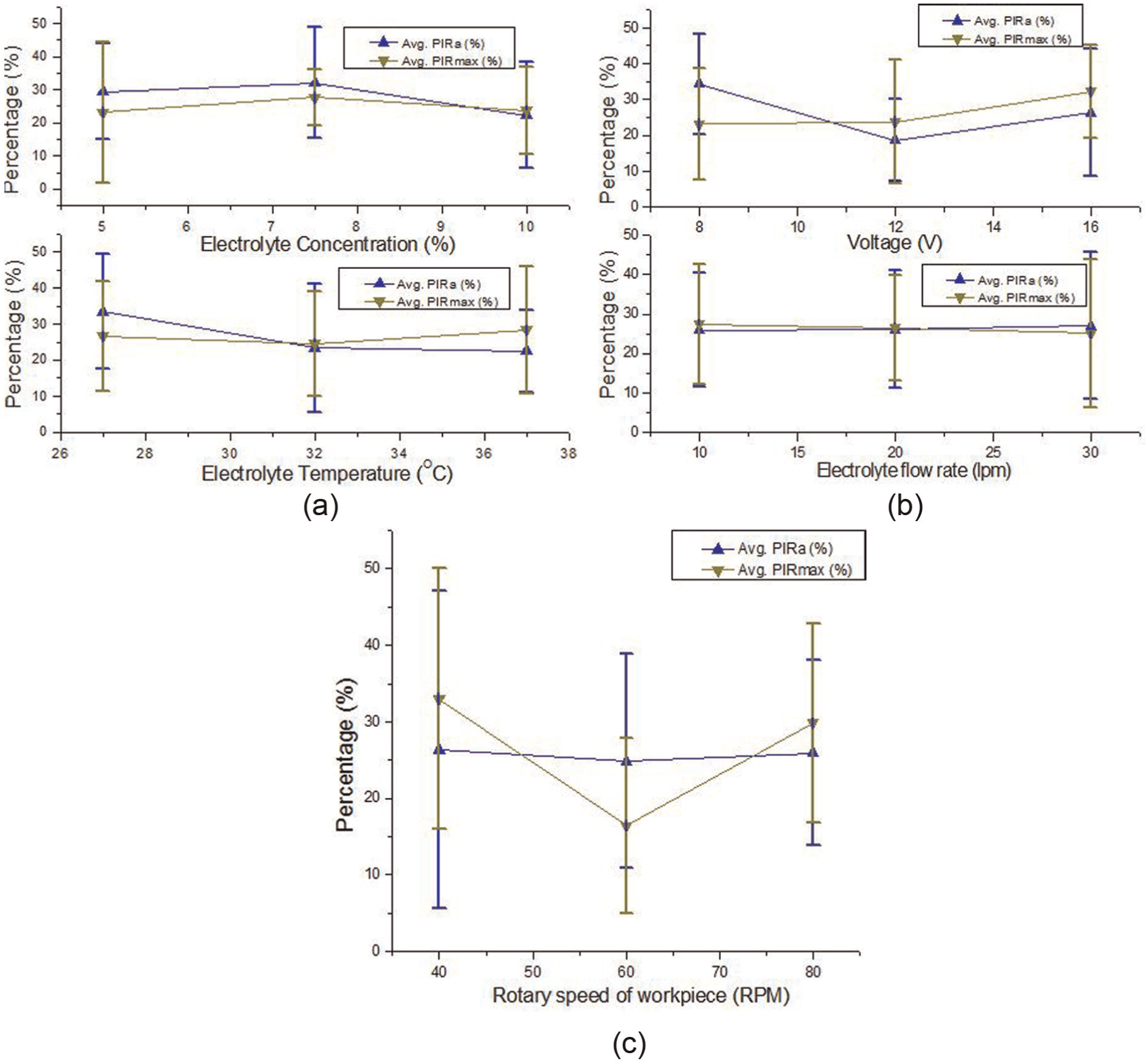
Variations in the values of average PIRa and average PIRmax with (a) electrolyte concentration and electrolyte temperature, (b) applied voltage and electrolyte flow rate and (c) rotary speed of the workpiece gear.
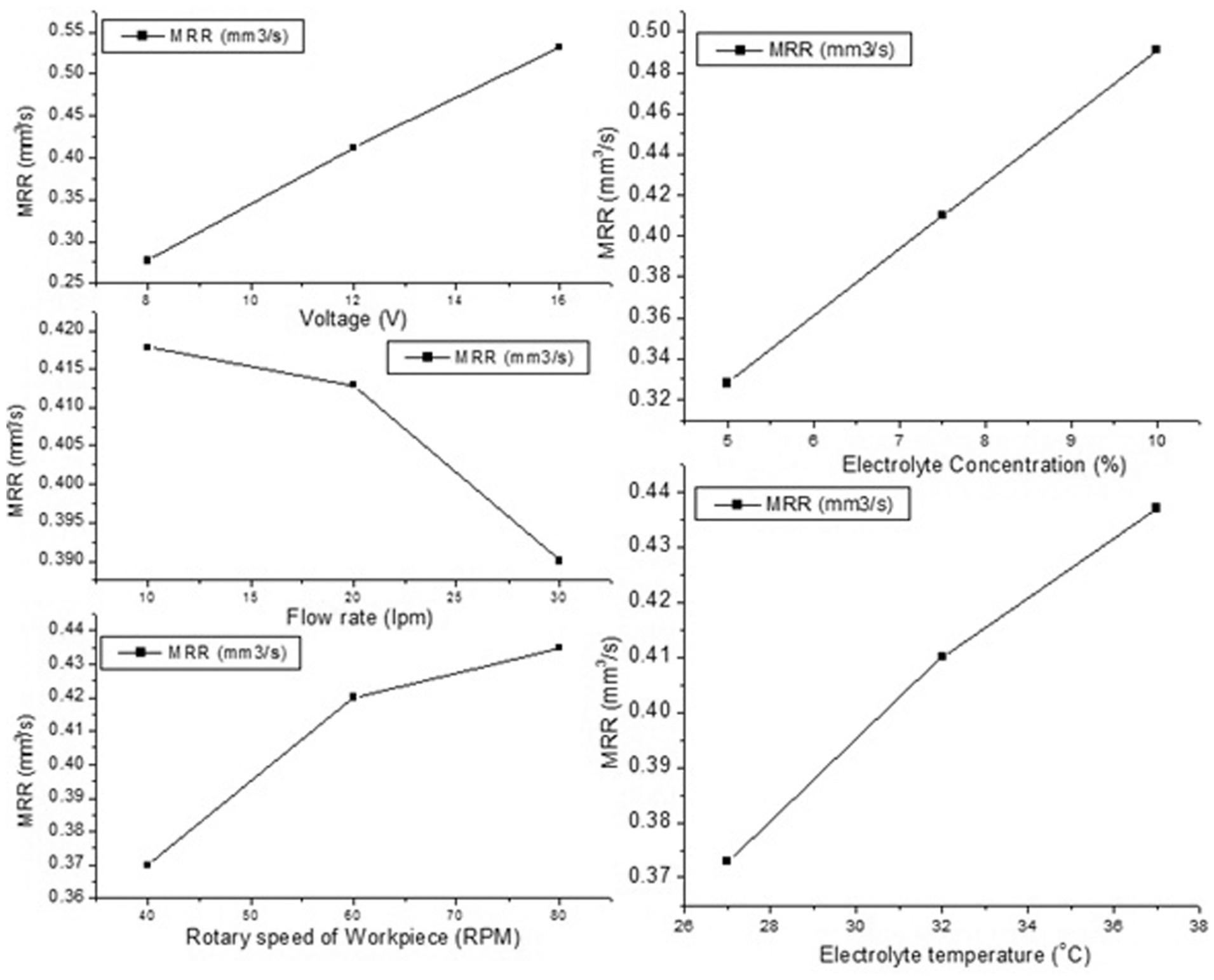
Variation in the average values of material removal rate (MRR) with electrolyte concentration, electrolyte temperature, applied voltage, electrolyte flow rate and rotary speed of the workpiece gear.
It is clear from Figure 4 that MRR increases with the increase in the electrolyte concentration, applied voltage, electrolyte temperature and rotary speed of the workpiece and decreases with the increase in the electrolyte flow rate. The obtained trends in MRR can be explained with the help of following points: (1) increase in the voltage and electrolyte concentration increases the amount of current and the number of free ions available for the conduction of current through IEG, respectively, thus increasing MRR; (2) increase in electrolyte temperature increases the electrolyte conductivity which results in higher MRR; (3) evolution of oxygen at the anode and possibility of change in valency of dissolution (for the workpiece material having multiple valency of dissolution); (4) higher rotary speed provides more number of cycles of electrolytic action and tends to give higher values of MRR; and (5) higher electrolyte flow rate decreases the MRR because it makes more amount of fresh electrolyte available for electrolytic action. This does not allow the electrolyte temperature to increase and also decrease ion concentration consequently reducing MRR.
Study of microstructure
The microstructure of the unfinished and ECH finished gears (using the parameters of experiment no. 13 of Table 3) was studied through scanning electron microscopic (SEM) images as shown in Figure 5(a) and (b). The surface roughness generated from the gear manufacturing operation is clearly visible in the SEM image of the unfinished gear (Figure 5(a)). This leads to noise and vibrations and reduces service life of the gears. Smoothening of the surface peaks present on unfinished gear tooth flank by the ECH process is visible as the white regions can be seen in the SEM image of the finished gears (Figure 5(b)). This smoothening results in quieter operation as well as enhanced service life of the bevel gears.
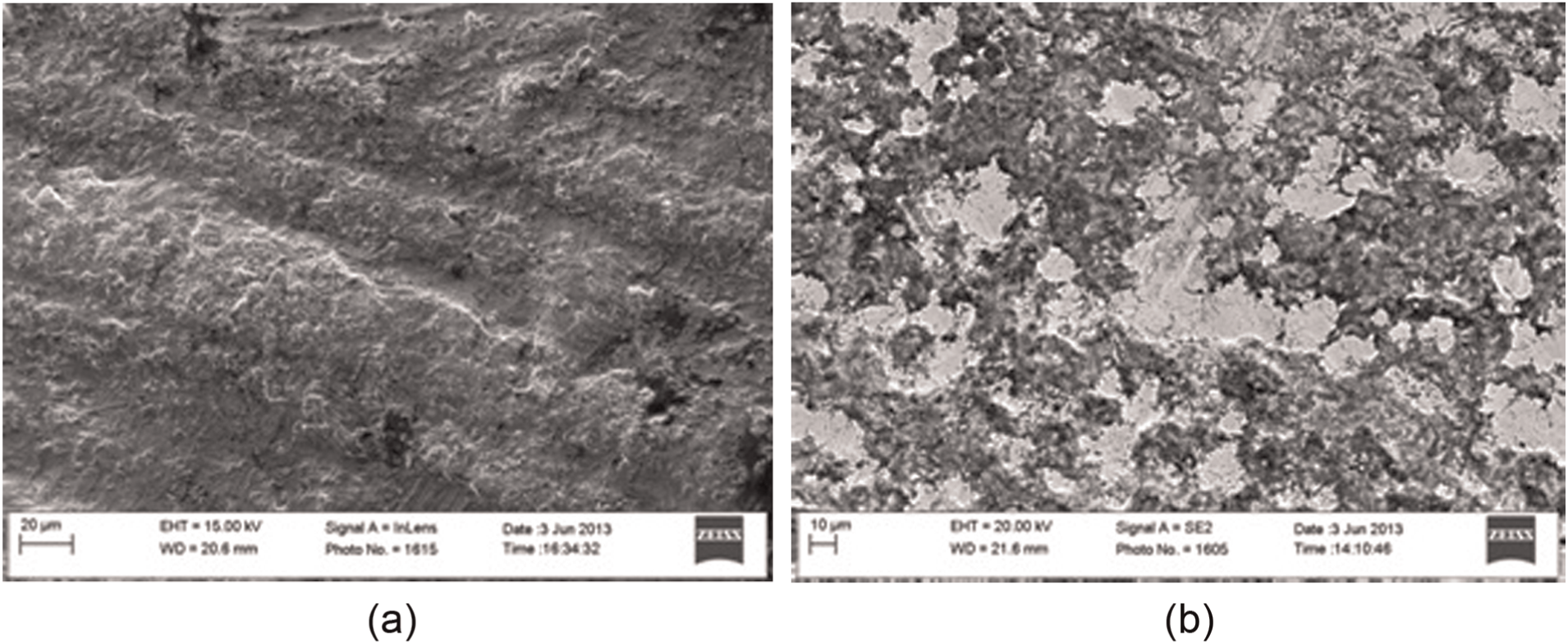
SEM images at 1000× of (a) an unfinished gear and (b) a gear finished by ECH.
Comparative study of ECM, honing and ECH
Table 2 presents the results of the comparative study of ECM, honing and ECH for finishing the bevel gear. Three different gears having same average and maximum surface values on the selected teeth were used for finishing by ECM, mechanical honing and ECH.
Comparison of bevel gear finishing by ECM, honing and ECH.
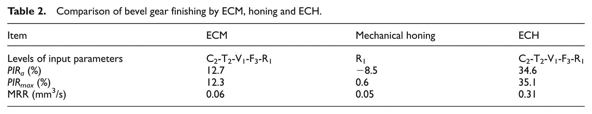
It is clear from this table that gear finishing by honing deteriorates average surface roughness (i.e. PIRa being −8.5%), while improvement in maximum surface roughness is insignificant (i.e. PIRmax being 0.6%) and very less MRR. ECM improves both average and maximum surface roughness (i.e. PIRa and PIRmax being 12.7% and 12.3%, respectively) with MRR being similar to honing. ECH gives much higher improvement in average and maximum surface roughness (PIRa and PIRmax being 34.6% and 35.1%, respectively) with much higher MRR. This can be explained by the fact that the honing action without using abrasives removes very less material from the workpiece surface, thus resulting in insignificant improvement in the surface finish. ECM gives more MRR which results in slight improvement in the surface finish, whereas ECH being combination of honing and ECM gives better surface finish and removes more material as compared to its constituent processes.
Figure 6(a)–(c) depicts the SEM images of the similar surfaces of the gear tooth flank finished by honing, ECM and ECH, respectively, at 1000× magnification. It can be seen from Figure 6(a) that the surface roughness produced on the gear tooth flank surface during the gear manufacturing operation and the surface defects are not smoothened by mechanical honing. The gear tooth flank surface finished by ECM (Figure 6(b)) shows more surface roughness due to etching and selective dissolution and presence of the metal oxide layer as compared to the similar gear flank surface finished by ECH (Figure 6(c)). It can be concluded from microstructure of the gear flank surfaces finished by ECM, honing and ECH and the data of Table 2 that the hybridization of ECM with honing enables ECH to give better surface quality as compared to its constituent processes.
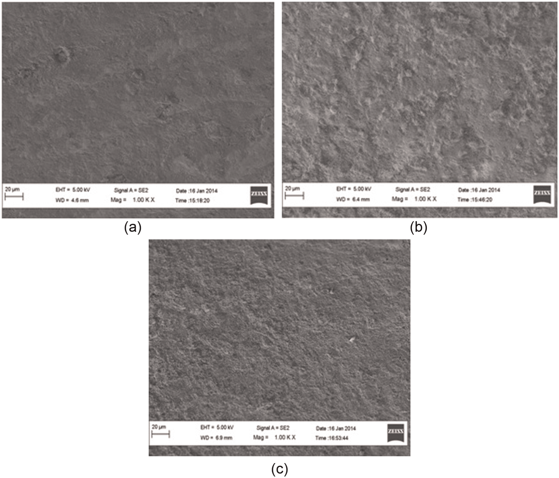
SEM images of bevel gear tooth flank surface at 1000× after finishing by (a) honing, (b) ECM and (c) ECH.
Conclusion
This article reported on improvement of surface finish of straight bevel gears by ECH process with an objective to develop ECH as an alternative productive and economical finishing for straight bevel gears. An experimental setup based on the principle of innovative concept of twin-complementary cathode gears was designed and developed. Effects of ECH parameters on the surface quality of the bevel gears and on ECH process productivity were investigated. Comparative study of ECM, honing and ECH was done to show the importance of hybridization of ECM and honing in improving the finishing capabilities of ECH. Following conclusions can be drawn from this study:
From the experimental results, maximum values of percentage improvement in maximum surface roughness (PIRmax) and MRR were obtained at higher values of electrolyte temperature and voltage, at middle level of electrolyte concentration and at lower value of rotary speed. Operating life of those components whose failure is either hazardous or very costly can be improved by attaining highest value of percentage improvement in maximum surface roughness since higher values of peak to valley distances are prone to crack propagation and consequently fatigue failure of the component.
Maximum value of percentage improvement in average surface roughness (PIRa) was achieved at lower values of electrolyte temperature and voltage and at middle level of electrolyte concentration. Rotary speed of workpiece gear did not affect PIRa significantly. Operating performance of those components whose breakdown is not a major problem can be improved by attaining highest value of percentage improvement in average surface roughness since smoother surface reduces the noise and vibration during the operation.
Electrolyte flow rate does not have any significant effect in improving the surface finish of bevel gears by ECH but MRR decreases with the increase in it.
Rotary speed significantly affects percentage improvement in maximum surface roughness.
The combination of ECH parameters identified from the experimental results giving the best combination of PIRa, PIRmax and MRR is 7.5% as electrolyte concentration; 32 °C as electrolyte temperature; 8 V as applied voltage; 30 L/min as electrolyte flow rate; and 40 r/min as rotary speed of the workpiece gear.
Comparative analysis proved usefulness of the hybridization of ECM and honing process because the values of PIRa, PIRmax and MRR obtained by ECH are far better than those achieved using ECM and honing individually.
This study helps to establish ECH as a viable alternative bevel gear finishing process which has potential to overcome the limitations of conventional bevel gear finishing processes.
Footnotes
Appendix 1
Values of the parameters of surface finish of bevel gear tooth before and after ECH and percentage improvements in them.
| Run no. | Input parameters | Responses | |||||||||||||||||||
|---|---|---|---|---|---|---|---|---|---|---|---|---|---|---|---|---|---|---|---|---|---|
| C (%) | T (°C) | V (V) | F (L/min) | R (r/min) | Volumetric MRR (mm3/s) | Tooth no. | Average surface roughness (Ra) | Maximum surface roughness (Rmax) | |||||||||||||
| Left-hand (LH) flank | Right-hand (RH) flank | Percentage improvement | Left-hand (LH) flank | Right-hand (RH) flank | Percentage improvement | ||||||||||||||||
| Before ECH (µm) | After ECH (µm) | Before ECH (µm) | After ECH (µm) | PIRa (%) LH flank | PIRa (%) RH flank | Average PIRa (%) | Before ECH (µm) | After ECH (µm) | Before ECH (µm) | After ECH (µm) | PIRmax (%) LH flank | PIRmax (%) RH flank | Average PIRmax (%) | ||||||||
| 01 | 5 | 27 | 8 | 10 | 40 | 0.20 | 01 | 1.8 | 0.7 | 2.6 | 1.6 | 60.2 | 35.6 | 42.4 | 10.3 | 5.3 | 8.2 | 7.0 | 48.9 | 14.7 | 1.7 |
| 09 | 1.6 | 1.1 | 1.7 | 0.96 | 30.3 | 43.8 | 10.0 | 17.0 | 9.0 | 7.9 | −69.0 | 12.4 | |||||||||
| 02 | 5 | 27 | 12 | 20 | 60 | 0.27 | 01 | 1.3 | 1.0 | 1.3 | 1.2 | 30.0 | 8.8 | 18.5 | 10.0 | 4.9 | 6.8 | 6.4 | 50.7 | 6.2 | 25.6 |
| 09 | 1.3 | 1.0 | 1.9 | 1.6 | 21.7 | 13.7 | 7.4 | 6.3 | 10.5 | 7.3 | 15.0 | 30.4 | |||||||||
| 03 | 5 | 27 | 16 | 30 | 80 | 0.36 | 01 | 2.3 | 1.0 | 1.7 | 0.98 | 55.2 | 43.0 | 42.9 | 8.7 | 5.2 | 13.9 | 6.0 | 40.2 | 56.8 | 47.9 |
| 09 | 1.7 | 1.0 | 2.1 | 1.3 | 34.7 | 38.42 | 11.2 | 5.6 | 13.3 | 7.4 | 50.3 | 44.3 | |||||||||
| 04 | 5 | 32 | 8 | 20 | 60 | 0.37 | 01 | 1.8 | 1.2 | 1.8 | 1.1 | 32.8 | 37.0 | 43.2 | 9.1 | 10.8 | 10.3 | 6.2 | −17.9 | 39.8 | 2.9 |
| 09 | 2.1 | 0.8 | 1.7 | 0.96 | 60.8 | 41.8 | 7.5 | 4.1 | 5.9 | 9.2 | 45.3 | −55.4 | |||||||||
| 05 | 5 | 32 | 12 | 30 | 80 | 0.34 | 01 | 1.4 | 1.6 | 2.6 | 2.2 | −10.5 | 17.0 | 14.1 | 7.3 | 10.9 | 10.7 | 11.2 | −50.8 | −4.7 | 1.2 |
| 09 | 1.8 | 2.0 | 3.3 | 1.4 | −8.8 | 58.7 | 10.1 | 8.1 | 13.6 | 8.1 | 19.9 | 40.4 | |||||||||
| 06 | 5 | 32 | 16 | 10 | 40 | 0.37 | 01 | 1.5 | 1.4 | 1.7 | 1.2 | 4.9 | 29.4 | 11.6 | 6.4 | 5.9 | 10.4 | 7.6 | 8.6 | 26.7 | 24.9 |
| 09 | 1.6 | 1.5 | 1.5 | 1.5 | 10.2 | 2.01 | 9.4 | 7.0 | 10.1 | 6.2 | 25.8 | 38.6 | |||||||||
| 07 | 5 | 37 | 8 | 30 | 80 | 0.28 | 01 | 1.5 | 1.3 | 2.2 | 1.0 | 17.6 | 54.2 | 39.1 | 8.5 | 7.0 | 9.0 | 5.2 | 17.2 | 42.1 | 35.2 |
| 09 | 1.8 | 0.97 | 1.9 | 1.2 | 47.2 | 37.5 | 12.8 | 5.3 | 12.7 | 9.8 | 58.6 | 23.1 | |||||||||
| 08 | 5 | 37 | 12 | 10 | 40 | 0.39 | 01 | 1.8 | 1.2 | 1.5 | 1.3 | 51.2 | 18.2 | 39.5 | 13.8 | 6.9 | 17.9 | 6.7 | 50.2 | 62.8 | 59.2 |
| 09 | 1.9 | 1.5 | 1.9 | 0.7 | 27.0 | 61.7 | 14.3 | 7.6 | 17.3 | 4.0 | 46.9 | 77.0 | |||||||||
| 09 | 5 | 37 | 16 | 20 | 60 | 0.38 | 01 | 1.4 | 1.9 | 2.5 | 2.7 | −34.3 | −6.3 | 12.6 | 8.8 | 11.4 | 11.0 | 15.8 | −28.9 | −43.3 | 9.2 |
| 09 | 2.5 | 1.4 | 2.3 | 1.2 | 42.8 | 48.5 | 35.4 | 14.0 | 20.0 | 10.2 | 60.3 | 48.9 | |||||||||
| 10 | 7.5 | 27 | 8 | 20 | 80 | 0.29 | 01 | 2.0 | 1.9 | 2.3 | 1.2 | 3.55 | 44.2 | 27.4 | 7.2 | 9.9 | 16.0 | 6.5 | −37.2 | 59.2 | 31.2 |
| 09 | 1.5 | 1.5 | 2.0 | 0.88 | 5.44 | 56.2 | 9.3 | 6.5 | 14.2 | 3.9 | 30.4 | 72.7 | |||||||||
| 11 | 7.5 | 27 | 12 | 30 | 40 | 0.28 | 01 | 1.0 | 1.2 | 1.7 | 1.4 | −12.9 | 14.7 | 1.4 | 16.3 | 8.5 | 8.3 | 8.70 | 47.7 | −4.6 | 22.7 |
| 09 | 1.6 | 1.7 | 2.2 | 1.9 | −9.19 | 13.2 | 13.7 | 9.4 | 11.9 | 10.0 | 31.6 | 16.0 | |||||||||
| 12 | 7.5 | 27 | 16 | 10 | 60 | 0.61 | 01 | 2.3 | 0.9 | 1.7 | 1.1 | 60.3 | 32.9 | 43.5 | 9.4 | 4.2 | 10.3 | 9.1 | 55.3 | 10.9 | 33.2 |
| 09 | 1.5 | 1.1 | 2.9 | 1.3 | 26.5 | 54.0 | 22.2 | 7.2 | 11.0 | 11.1 | 67.4 | −0.9 | |||||||||
|
|
|
|
|
|
|
|
|
|
|
|
|
|
|
|
|
|
|
|
|
|
|
|
|
|
|
|
|
|
|
|
|
|
|
|
|
|||||||||
| 14 | 7.5 | 32 | 12 | 10 | 60 | 0.40 | 01 | 1.4 | 1.4 | 2.0 | 1.1 | −2.09 | 44.3 | 11.7 | 11.6 | 7.7 | 9.6 | 8.3 | 34.2 | 13.6 | 24.8 |
| 09 | 1.7 | 1.6 | 1.4 | 1.5 | 9.5 | −4.9 | 8.2 | 6.5 | 8.6 | 6.0 | 21.2 | 30.4 | |||||||||
| 15 | 7.5 | 32 | 16 | 20 | 80 | 0.56 | 01 | 1.4 | 1.5 | 3.6 | 1.7 | −4.6 | 53.8 | 33.6 | 10.0 | 6.8 | 13.6 | 8.02 | 32.1 | 41.2 | 38.4 |
| 09 | 1.7 | 0.7 | 2.0 | 1.5 | 58.1 | 27.1 | 11.1 | 4.7 | 11.4 | 8.8 | 57.3 | 23.0 | |||||||||
| 16 | 7.5 | 37 | 8 | 10 | 60 | 0.24 | 01 | 1.5 | 1.4 | 1.4 | 1.2 | 5.3 | 15.9 | 28.9 | 10.8 | 9.1 | 9.5 | 6.4 | 16.0 | 32.6 | 20.9 |
| 09 | 2.3 | 1.4 | 2.7 | 1.2 | 40.5 | 54.1 | 7.1 | 8.4 | 24.2 | 11.4 | −17.7 | 53.0 | |||||||||
| 17 | 7.5 | 37 | 12 | 20 | 80 | 0.50 | 01 | 1.6 | 1.0 | 1.8 | 1.1 | 52.9 | 38.2 | 20.9 | 7.2 | 5.1 | 10.1 | 4.0 | 28.8 | 60.5 | 33.0 |
| 09 | 1.7 | 1.4 | 1.4 | 1.8 | 22.6 | −30.0 | 11.4 | 6.6 | 8.5 | 8.5 | 42.3 | 0.7 | |||||||||
| 18 | 7.5 | 37 | 16 | 30 | 40 | 0.54 | 01 | 2.7 | 2.5 | 1.7 | 1.4 | 7.3 | 15.5 | 22.4 | 8.2 | 5.4 | 9.4 | 7.0 | 34.5 | 25.8 | 43.7 |
| 09 | 2.3 | 1.9 | 3.6 | 1.8 | 17.7 | 49.3 | 14.2 | 8.0 | 27.9 | 8.0 | 43.4 | 71.3 | |||||||||
| 19 | 10 | 27 | 8 | 30 | 60 | 0.31 | 01 | 2.1 | 1.8 | 4.2 | 1.1 | 16.2 | 73.0 | 38.7 | 12.9 | 21.6 | 8.6 | 5.9 | −67.5 | 31.5 | 8.6 |
| 09 | 1.2 | 1.3 | 2.4 | 0.67 | −6.8 | 72.5 | 6.2 | 6.2 | 13.6 | 4.0 | −0.3 | 70.5 | |||||||||
| 20 | 10 | 27 | 12 | 10 | 80 | 0.49 | 01 | 1.1 | 1.1 | 2.1 | 1.3 | 2.7 | 36.3 | 31.8 | 4.9 | 4.3 | 9.2 | 7.0 | 13.0 | 24.3 | 22.7 |
| 09 | 2.0 | 0.8 | 1.3 | 0.9 | 57.2 | 30.8 | 10.3 | 6.9 | 5.8 | 4.62 | 33.0 | 20.6 | |||||||||
| 21 | 10 | 27 | 16 | 20 | 40 | 0.55 | 01 | 1.2 | 1.0 | 2.0 | 0.6 | 17.9 | 70.2 | 54.3 | 5.3 | 5.6 | 9.7 | 3.9 | −7.2 | 59.4 | 45.8 |
| 09 | 1.7 | 0.7 | 2.4 | 0.7 | 58.7 | 70.6 | 8.3 | 3.3 | 11.5 | 3.3 | 60.0 | 70.9 | |||||||||
| 22 | 10 | 32 | 8 | 10 | 80 | 0.30 | 01 | 1.5 | 1.0 | 1.1 | 1.1 | 54.5 | 0.0 | 16.7 | 8.9 | 3.6 | 12.4 | 5.2 | 59.0 | 57.5 | 34.0 |
| 09 | 1.4 | 0.8 | 0.7 | 1.2 | 73.2 | −60.8 | 9.3 | 5.1 | 6.5 | 8.1 | 44.5 | −24.6 | |||||||||
| 23 | 10 | 32 | 12 | 20 | 40 | 0.50 | 01 | 1.5 | 1.2 | 2.4 | 1.4 | 17.2 | 41.7 | 11.3 | 7.0 | 5.1 | 11.8 | 6.9 | 26.8 | 41.7 | 24.9 |
| 09 | 2.3 | 1.8 | 1.7 | 2.4 | 29.1 | −42.9 | 13.9 | 10.2 | 8.5 | 8.1 | 26.8 | 4.9 | |||||||||
| 24 | 10 | 32 | 16 | 30 | 60 | 0.66 | 01 | 1.3 | 0.9 | 1.4 | 1.7 | 42.8 | −24.1 | 8.3 | 6.0 | 4.5 | 9.0 | 7.3 | 24.4 | 19.9 | 22.4 |
| 09 | 1.5 | 1.0 | 1.1 | 1.4 | 47.6 | −33.3 | 28.8 | 8.2 | 5.3 | 6.7 | 71.4 | −25.8 | |||||||||
| 25 | 10 | 37 | 8 | 20 | 40 | 0.30 | 01 | 1.6 | 1.7 | 1.4 | 1.1 | −9.5 | 21.9 | 13.8 | 13.6 | 11.8 | 8.6 | 5.5 | 13.6 | 36.4 | 29.5 |
| 09 | 3.0 | 1.4 | 1.3 | 1.4 | 52.5 | −9.5 | 15.6 | 8.3 | 9.3 | 7.3 | 46.8 | 21.1 | |||||||||
| 26 | 10 | 37 | 12 | 30 | 60 | 0.54 | 01 | 1.8 | 0.9 | 2.4 | 1.7 | 50.8 | 27.7 | 18.5 | 10.0 | 3.3 | 3.4 | 8.1 | 67.0 | −135.4 | 0.14 |
| 09 | 0.8 | 1.0 | 1.5 | 1.1 | −30.0 | 25.3 | 12.0 | 5.9 | 11.9 | 9.7 | 50.7 | 18.3 | |||||||||
| 27 | 10 | 37 | 16 | 10 | 80 | 0.77 | 01 | 2.4 | 1.2 | 1.9 | 1.2 | 51.0 | 34.0 | 7.0 | 8.9 | 6.1 | 10.3 | 6.8 | 31.1 | 34.2 | 24.5 |
| 09 | 0.9 | 0.98 | 1.1 | 1.8 | −4.08 | −53.0 | 5.3 | 5.8 | 15.4 | 9.1 | −8.2 | 40.8 | |||||||||
Bold values signify the values of input parameters for which maximum values of responses are obtained.
Acknowledgements
The authors acknowledge their gratitude toward SnH Gears, Dewas, Madhya Pradesh, India, for providing their facilities for fabrication of the bevel gears and VE Commercial Vehicles, Pithampur, Madhya Pradesh, India, for allowing to use their facilities for surface roughness measurements.
Declaration of conflicting interests
The authors declare that there is no conflict of interest.
Funding
This study was supported by CSIR, New Delhi, India, through project no. 22/(0468)/09/EMR-II.