
Abstract
The coexistence of high levels of strength and toughness is necessary for the microalloyed steels used in natural gas pipelines. The welding thermal cycle can significantly change the microstructures and therefore the mechanical properties of the girth welded pipelines. Thus, the experimental investigation on the welded material properties is required for assessing the structural integrity of the pipelines. In this article, the metallurgical characteristics of the multi-pass girth welds on API X70 steel pipes with 56 in outside diameter and 0.780 in wall thickness were determined for the first time using chemical analysis and standard metallography. The chemical analysis showed different chemical compositions in different weld passes. The amount of carbon in the weldment increased in comparison with the base metal, although the microalloy elements in the weld gap decreased by increasing the pass number. The metallographic investigation by optical microscope demonstrated the different microstructures in different sub-zones of the welded joint. The images obtained from scanning electron microscope also presented the dendritic and acicular structures in the root and cap passes, respectively. The observed hard phases in the weldment, such as martensite, had direct effects on the mechanical properties of the weldment and heat-affected zone.
Keywords
Introduction
The girth welds are critical zones in natural gas transmission pipelines. 1 The most common joining method of gas transmission pipelines is girth welding, conducted automatically or manually. 2 Welding includes about 25% of the pipeline construction project, which requires the highest degree of welding skill. 3 Sometimes, during welding, a large amount of the main alloying elements of the base metal will burn. 4 Due to the high importance of the welded zone in welded pipelines, its quality should be controlled by non-destructive testing and standard microstructural examinations. 5 In order to assess the structural integrity of the pipelines, the mechanical and microstructural properties of the weld zone must be examined completely.
The mechanical properties of the microalloy steels reported by the pipe manufacturers are too conservative, although some differences in the reported properties of different manufacturers were observed. Therefore, the experimental examination of the mechanical and microstructural properties of the welded joint in these steels has attracted much attention.6,7 In API X70 steel, the microalloy elements such as titanium, vanadium and niobium have a great propensity to combine with carbon and nitrogen during welding.8,9 These combinations such as nitrides, carbides and carbo-nitride particles increase the strength of the weldment significantly. On the contrary, high temperature of welding process may lead to the non-uniform distribution of these particles which consequently decrease the weld strength. 10
Research background
In spite of great development in computational hardware and software, employment of experimental methods for investigation on the welding matters is still the first choice. Several studies have been done in recent years in order to evaluate the mechanical and metallurgical properties of the circumferential pipe welding joints due to their large applications.11–13 In a comprehensive study, Hammond and colleagues14,15 examined the properties of girth weld in gas transmission pipelines. In 2009, Hashemi et al. 16 investigated the relationship between microstructure and impact strength of X70 steel in spiral weld gap. In 2012, Hashemi and Mohammadyani 17 studied hardness and impact strength of the spiral welds in X70 steel with regard to its microstructures. They reported large increases in hardness and decreases in impact strength of the weld zone. In 2007, Cao et al. 18 investigated the effect of niobium on isothermal austenite to ferrite transformation in high-strength low alloy (HSLA) steels. They investigated the kinetics of the isothermal austenite-to-ferrite transformation in two different HSLA steels with different amounts of niobium. They concluded that NbC precipitation and the presence of solute niobium could influence the transformation of austenite to ferrite. In 2013, Al-Abbasi 19 predicted the deformation behavior of ferrite–perlite steels using micro-mechanical modeling of cells. He developed a model based on micro-mechanical modeling of cells to capture the mechanical behavior of the dual phase ferrite–perlite steels. The model developed was employed to capture the deformation behavior, both in terms of the stress–strain trend and the deformation fields of the constituents with increase in the volume fraction of the second phase. In 2005, Paniagua-Mercado et al. 20 investigated the influences of the flux chemical composition on the microstructure and tensile strength of the submerged-arc welds (SAW). In this research, microstructure and macrostructure of the weldment were studied using optical and scanning electron microscopes (SEMs). The acicular ferrite (AF) microstructure was observed in the welds with fluxes which contain titanium oxide. They reported that the yield and ultimate tensile strengths were influenced by the presence of AF. They also observed that elongation and area reduction percentages were affected by the inclusion volume percentage. In 2008, Vega et al. 21 investigated the effects of multiple repairs on the mechanical properties of the girth welds of pipelines. They reported insignificant changes in the microstructural constituents of the weld heat-affected zone (HAZ), but the grain size was increased in each weld repair pass. In 2008, Kolhe and Datta 22 studied the microstructure and mechanical properties of multi-pass SAW. They reported spheroidizing, partial transformation, grain refinement and grain growth in different parts of the weld and its HAZ. In 2009, Wang et al. 23 investigated the high-strength pipeline steels with different microstructures. They studied the mechanical properties of a commercial X70 grade polygonal ferrite (PF) dominated pipeline steel and a laboratory developed X90 grade AF dominated pipeline steel obtained by optimum thermomechanical controlled processing (TMCP). Charpy impact test results indicated that the upper shelf energy of the AF pipeline steel was a little bit higher, but its energy transition temperature was extremely lower than that of the PF pipeline steel.
In this article, the metallurgical characteristics and chemical properties of the multi-pass girth weld in API X70 steel pipes with 56 in outside diameter and 0.780 in wall thickness were determined in different portions of the weld and HAZ. These experimental studies are useful in order to evaluate the structural integrity of the gas transmission pipelines.
X70 steel pipes
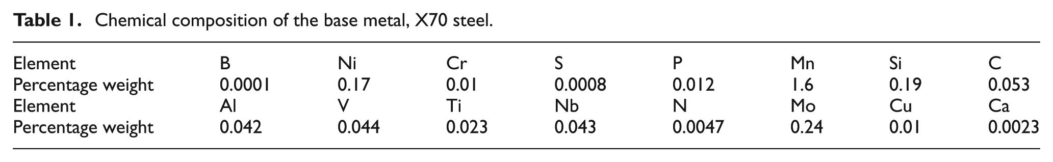
The tested pipe in this study is a spiral seam welded pipe made from X70 steel which was formed and welded in Sadid Pipe and Profile Company. These pipes were employed in the high-pressure national gas transmission pipelines of Iran. X70 is a kind of high-strength, low-alloy steel which has significant amounts of microalloy elements such as titanium, vanadium and niobium. Table 1 shows the chemical composition of this steel.
Chemical composition of the base metal, X70 steel.
Specimen preparation and welding
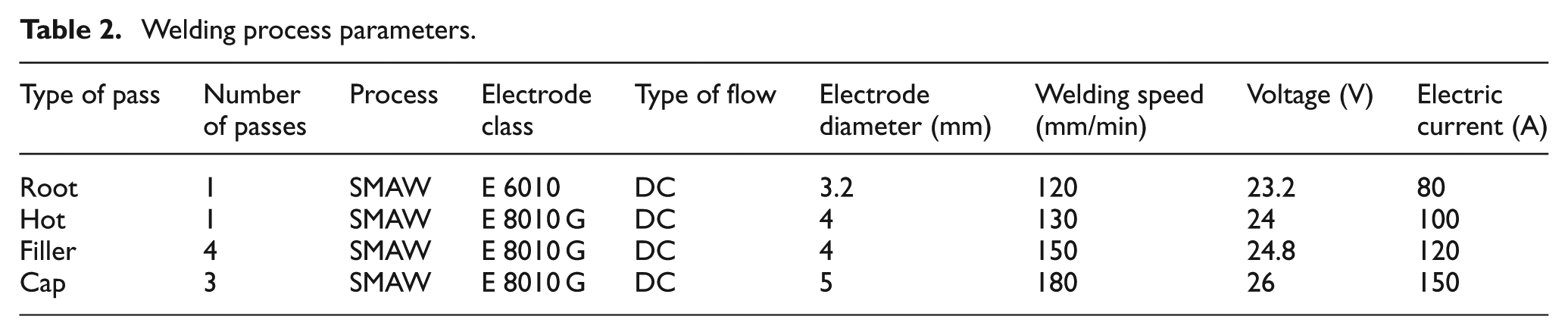
Two pieces of 50 cm length of spiral steel pipes from API X70 were welded together in nine passes. In Table 2, the welding process parameters for each pass are reported. As specified in Table 2, the electrode diameter and the welding current were increased from the root pass to the cap passes. The welding procedure specification for these pipes was based on AWS standard. The preheat temperature of 100 °C and the inter-pass temperature of about 100 °C–250 °C were considered.
Welding process parameters.
According to the standard, no tack weld was used for setting up the pipes for welding. So in order to position and fix the pipes during the welding, two sides of the pipes were welded to steel columns as shown in Figure 1(a). The distance between two pipes was adjusted to be 3.2 mm (Figure 1(c)). The beveling was implemented by machining according to the AWS standard. The schematic view and geometrical dimensions of the weld groove are presented in Figure 1(b).
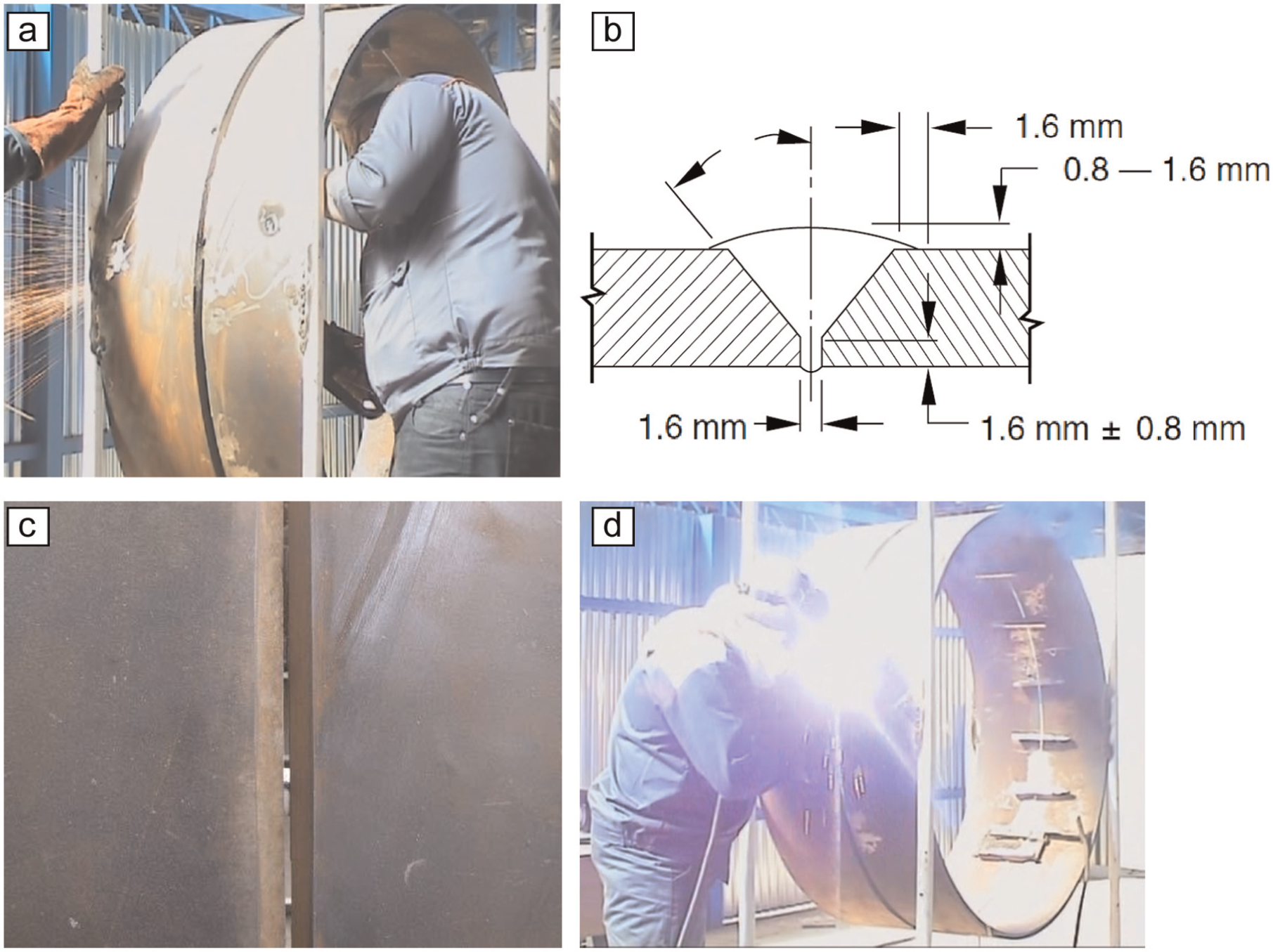
(a) Jig and fixture for girth welding, (b) schematic view and dimensions of the weld groove, (c) pipes positioning before welding and (d) girth welding.
After cleaning the weld cap and removing the chips and contamination, welding was performed as shown in Figure 1(d). Figure 2 shows the initial and cap passes of the girth welded joint. The welding procedure was approved by conducting the Procedure Qualification Record (PQR) tests.
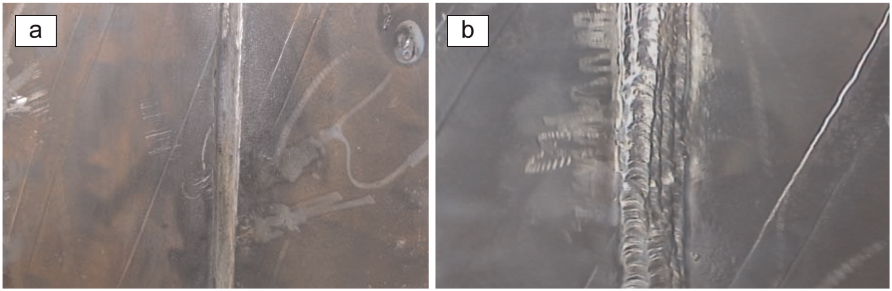
Welding different passes: (a) initial pass and (b) cap passes.
After each pass, welding slags were removed by grinding machine. In order to check the quality of the welded joint, visual inspection was performed after each pass. Liquid penetrant and radiographic test were also used to ensure the quality of the weld joint.
Metallurgical investigation
Quantometery
In order to investigate the chemical properties of each pass, the chemical composition for weldment and HAZ areas were obtained using spark alloy elements quantometer. The surface preparation and testing were done according to ASTM A415-08. Figure 3 represents the spark zone for each test. The average chemical composition for each spark zone was obtained.
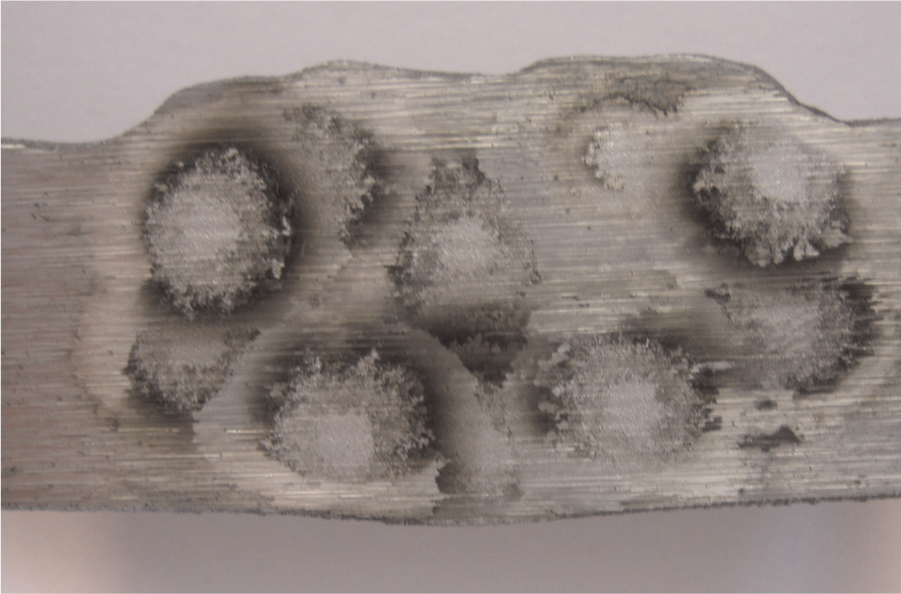
Spark zone in quantometery for weldment and HAZ.
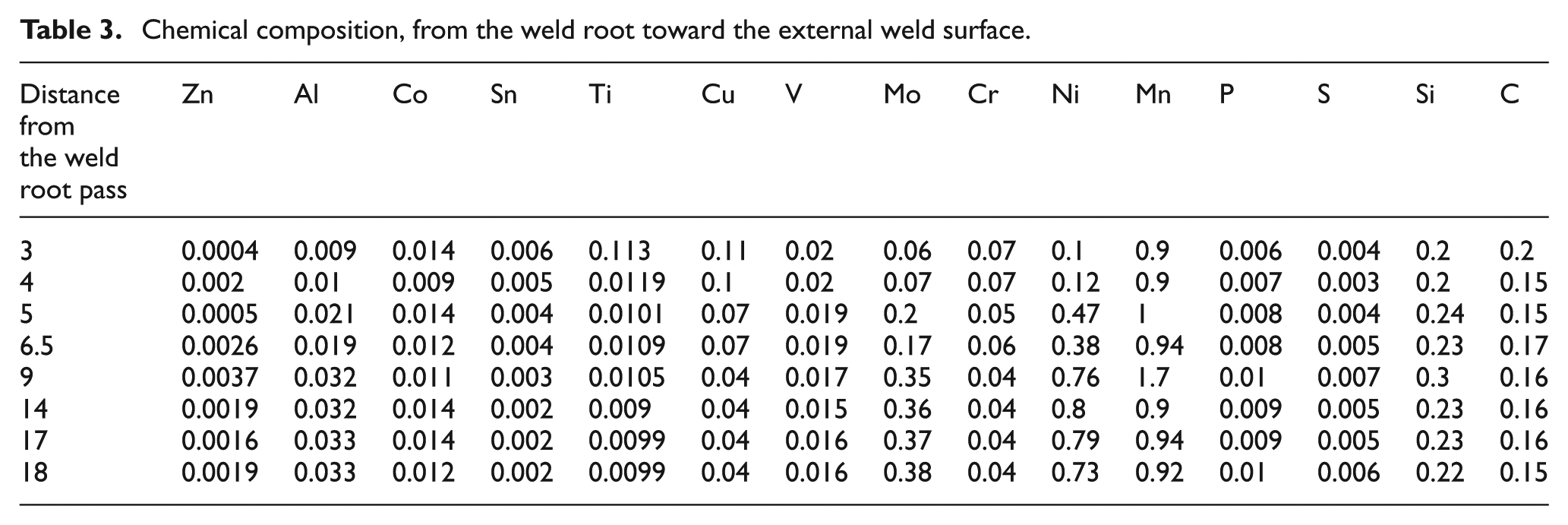
Table 3 shows the quantometer test results for the weldment, from the weld root toward the external weld surface. It was observed that the microalloy element content, especially vanadium, decreased from root pass to cap passes.
Chemical composition, from the weld root toward the external weld surface.
Metallography
The specimen for metallography was prepared according to ASTM E 3. First, the surface of the specimen was finished by sandpapers of P600, P800 and P1000 grades. Then 1-μm diamond paste and 0.05-μm alumina powder were employed for polishing; 3% natal etching solution was used for etching according to ASTM E 407. Different weld zones are shown in Figure 4.
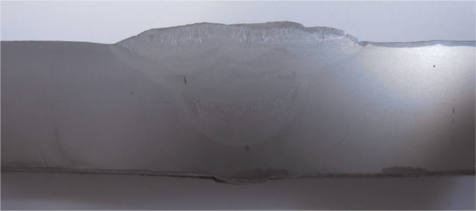
Different weld zones after etching.
An optical microscope of type ECLIPSEE 200 MVR with 1000 times magnification was used for metallographic study. The obtained images from the root, hot, filler and cap passes are presented in Figure 5. The subscript numbers 1, 2, 3 and 4 are related to root, hot, filler and cap passes, respectively. The boundaries between the weldment and the base metal, especially for the root pass, are quite obvious in Figure 5(b).
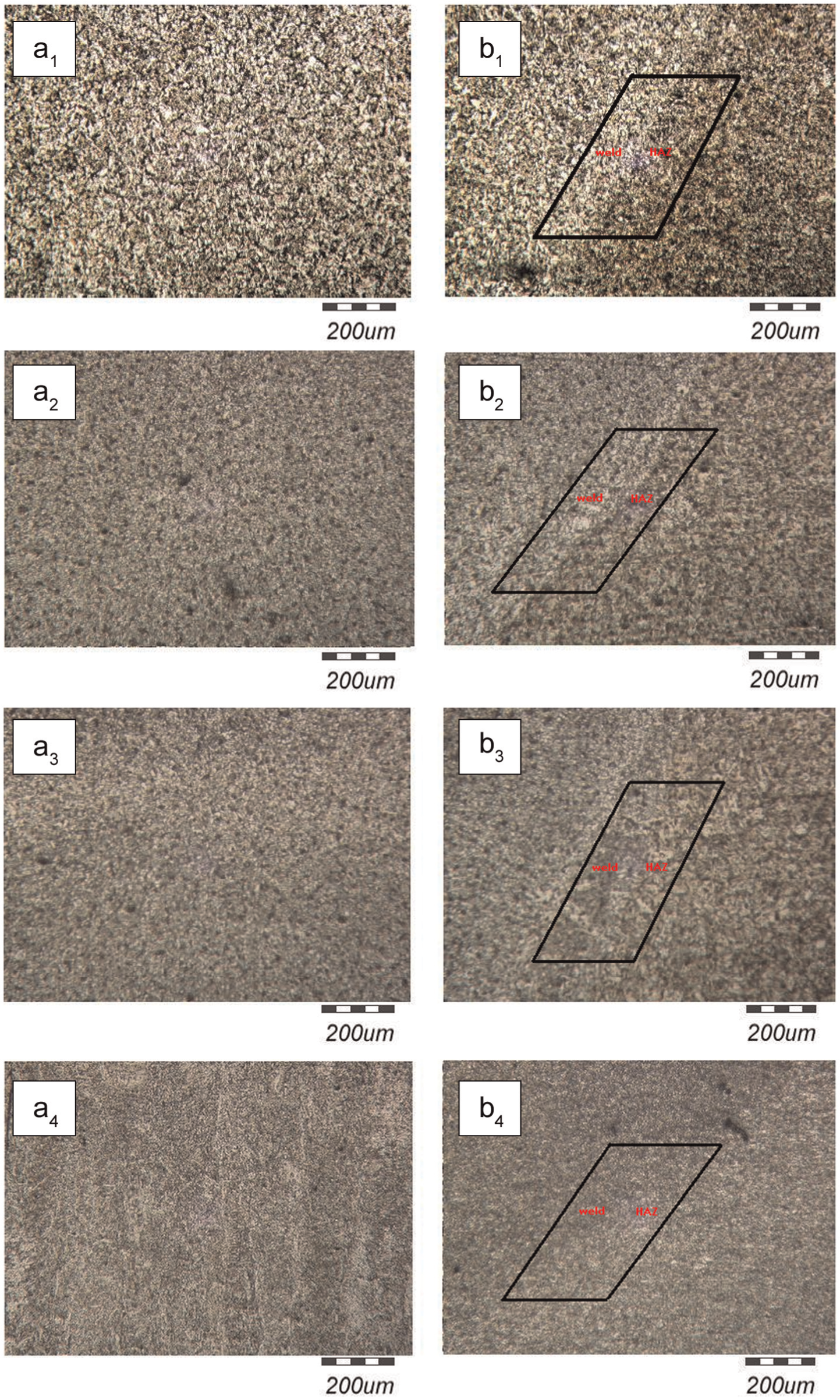
Optical microscope images from the root (1), hot (2), filler (3) and cap (4) passes: (a) weld metal and (b) weld metal at right side and HAZ at left side.
In order to identify the metallurgical phases and the grain size in different weld zones, optical microscope images with 500× magnification were captured (Figure 6). The pictures depict the different microstructures in different weld zones.
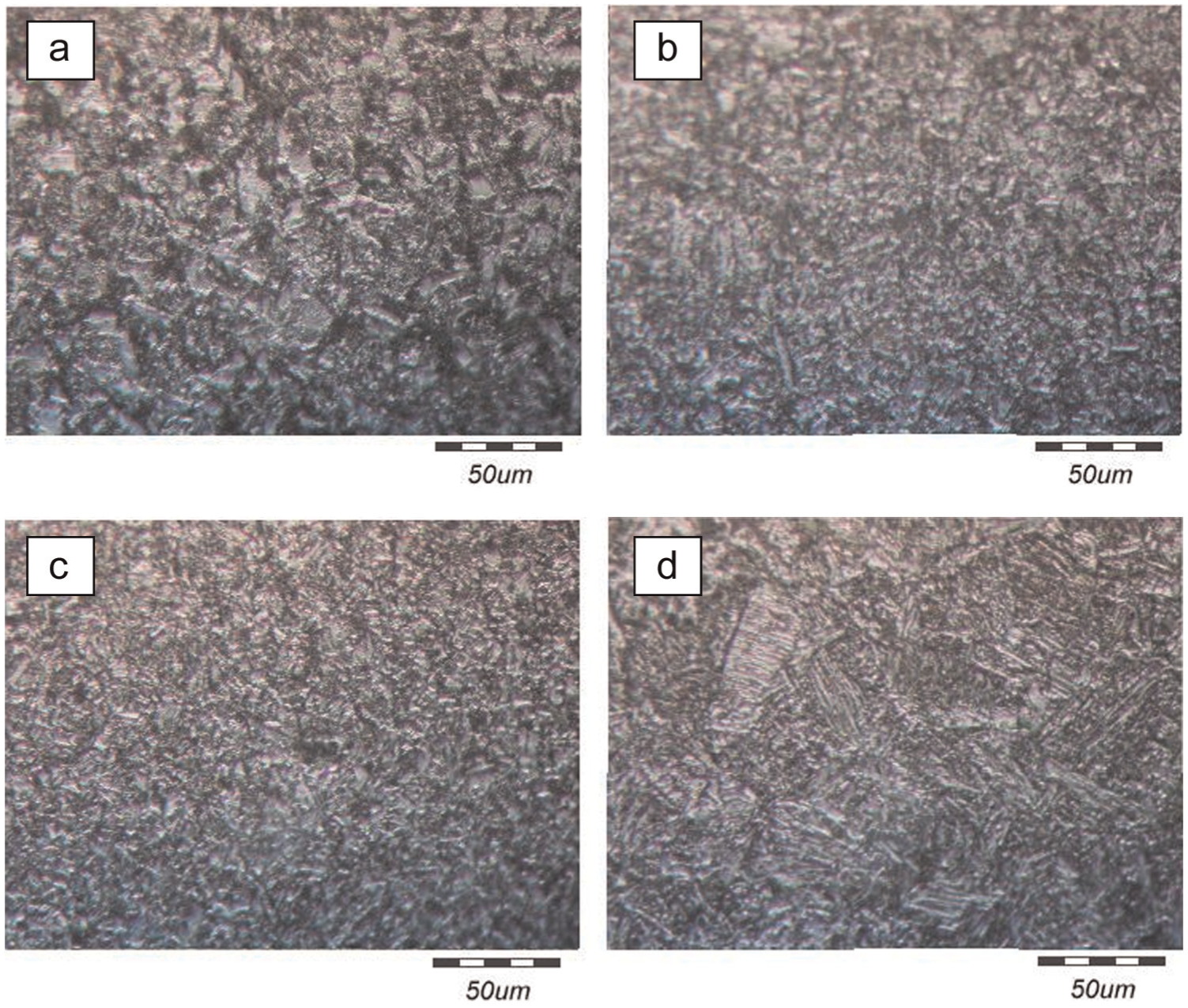
Weld-zone microstructure: (a) root pass, (b) hot pass, (c) filler pass and (d) cap pass.
For more evaluation and morphology observation, the SEM images were also made. Figure 7 shows the base metal microstructure with 3000× magnifications. The cementite colonies in the ferrite are apparent in this image.
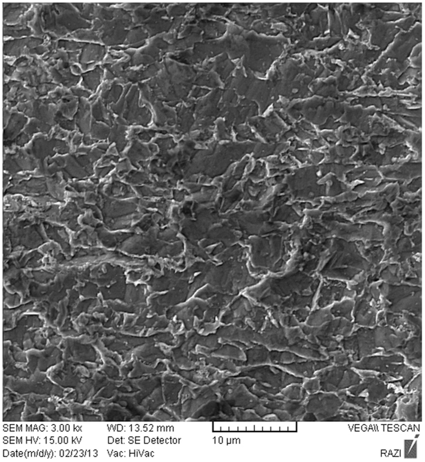
SEM image of the base metal, magnification 3000×.
The obtained SEM images from the root, hot, filler and cap passes are presented in Figure 8. The subscript numbers 1, 2, 3 and 4 are related to root, hot, filler and cap passes, respectively. Labels “a” and “b” are used for HAZ and weld metal images, respectively. The obtained results from SEM images were in accordance with optical microscopy results.
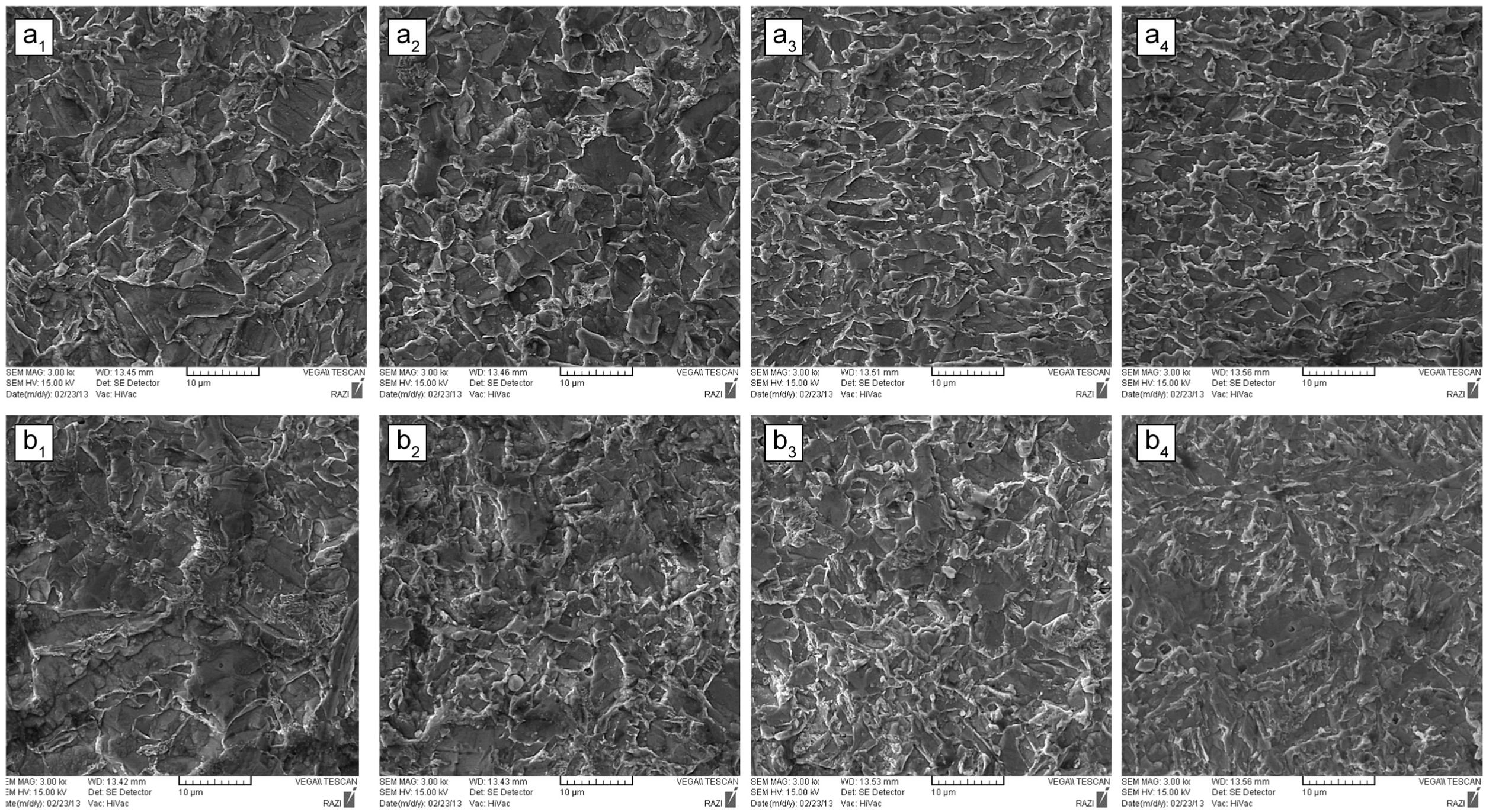
SEM images with 3000× magnification, from the root (1), hot (2), filler (3) and cap (4) pass: (a) HAZ and (b) weld metal.
Discussion
Quantometery results
The chemical composition of the base metal and weldment are reported in Tables 1 and 3, respectively. The differences in chemical composition led to differences in mechanical and metallurgical properties. The chemical composition in different weld passes were also changed significantly.
Changes in welding current, electrode size and welding speed resulted in different welding heat input. Different welding heat input in different passes changed the amount of melted base metal which mixed with the melted electrodes during the welding. So different chemical compositions in different weld passes were observed. Surface contaminations that remained on the joint surface and slag that remained from previous passes could also make these differences.
The different chemical composition of the root pass can be explained by the different electrode types used in this pass. Microalloy elements such as titanium and vanadium decreased from the root pass toward the final pass. These microalloy elements might be burned by the severe welding heat input or withdrawn from the weld zones as the slag.
Metallography results
Microstructure analysis presented in Figures 5, 6 and 8 revealed some useful results. Studying the microstructure was performed using CLEMEX, a specialized software which used the point count approach for estimating the phase percentage.
Root pass microstructures
As observed in Figures 6 and 8, the weld root contained the layered tempered martensite with complex carbides (M7C3). Martensite transformation occurred as a result of high cooling rate after root pass welding. Martensite has a body centered tetragonal (BCT) crystal structure. This martensite structure was tempered due to thermal cycle applied during the next passes. The alloying elements such as chrome, manganese and molybdenum were coming out from the retained austenite. These elements generated some complex carbide with the exited carbon atoms from the martensite lattices. These carbides are apparent as some small bright spots in metallography images in Figure 6.
The CLEMEX software calculated 44% of dark phases of layered tempered martensite, 56% of white ferrites and little amounts of perlite and complex carbide for the root pass. The grain size was measured according to the ASTM standard. The average grain sizes in the root weldment and root HAZ are about 64 and 128 μm, respectively. The root HAZ also had 60% of perlite, 40% of retained austenite and peritectoid ferrite and limited amount of complex carbides and layered martensite. It must be noted that due to less amount of carbon, the hardenability of the weld metal is not much. The Grade 60 electrodes used for the root pass welding have chemical composition similar to the base metal. Due to high cooling rate during the welding and consequently limited time for diffusion, small amount of ferrite was created. As observed in Figure 8 (a1 and b1), the morphology of the root pass and its HAZ is dendritic, and few co-axis grains were observed.
Hot passes microstructures
The amount of observed phases in hot passes is very different from the root pass. The metallography images presented about 65% of dark areas of tempered martensite and perlite colonies; 35% of white peritectoid ferrite and a little amount of Widmanstätten ferrite, and some austenite phases were also observed. The average of measured grain size in this zone is about 128 μm.
An electrode of Grade 80 was used for hot passes. Different electrode type and electrode size, different heat inputs due to current changes and different heat sink due to geometry changes in hot passes changed the obtained phases as welding.
Perlite colonies in this area are more evident. Martensite grains were also tempered. Some of the remaining austenite grains were transformed into peritectoid ferrite due to applied heat during the next passes. About 67% of bright grains of austenite and peritectoid ferrite, 33% of dark layered martensite and perlite colonies and little amount of complex carbides were observed in the HAZs beside the hot passes. The measured grain size in this area was approximately 64 μm.
Filler pass microstructures
In filler pass zone, 62% of dark martensite, 38% of perlite colonies and also a small amount of retained austenite and complex carbide were observed. The microstructures of filler pass were similar to hot pass, and only a small reduction in dark martensite phases was observed. Due to high welding speed for filler and cap passes and consequently less welding heat input in these passes, the martensite phases in this zone remained untempered. As observed in Figures 8 (b2 and b3), by increasing the pass number, dendrite grains were decreased and more co-axis structure was observed in the weld structure.
In HAZs beside filler passes, about 47% of dark layered martensite and perlite colonies, 53% of bright retained austenite and peritectoid ferrite and small amount of complex carbides were observed. The differences in the amounts of observed phases can be explained by the difference in applied heat from the previous and the next passes in this zone. The average grain size in the weld and HAZ of this area was similar to the hot pass zone.
By increasing the pass number, the dendrite grains of the HAZ were decreased and the stretched grains were observed, as shown in Figures 8 (a2 and a3)
Cap passes microstructures
About 75% of dark layered martensite, 25% of white retained austenite and small amount of complex carbides were revealed in the cap passes. Increase in martensite and the disappearance of perlite can be explained by the larger electrode size and the higher welding current which led to higher welding heat input in these passes. Completing the weld geometry led to more heat sink in these passes, which causes the higher quenching rate. More martensite phases were created as a result of intense heating and cooling cycle in this zone. Martensite transformation leads to increase in grain volume, which reduces the welding residual stresses.
As there were no more welding passes over this zone, the martensite phases were not tempered. The cap passes had needle-shaped morphology, which are presented in Figure 8 (b4). In Figure 8 (a4), some co-axis grains were also observed in this zone. The HAZ beside these passes contained about 59% of dark layered martensite and perlite colonies, 41% of peritectoid ferrite and retained austenite and small amount of complex carbides.
Conclusion
In this article, the metallurgical characteristics and chemical properties of the multi-pass girth weld in API X70 steel pipes with 56 in outside diameter and 0.780 in wall thickness were determined in different parts of the weld and HAZ. These experimental findings are useful in the evaluation of the structural integrity of the gas transmission pipelines. The obtained results show various metallurgical properties of the weld and HAZ of the API X70 steel welded pipes. The significant results of this study are listed as follows:
The carbon content of the weldment was higher than the base steel.
The microalloy elements such as titanium, vanadium and curium decreased from the root pass toward the cap passes. But the molybdenum and nickel had a reverse changing trend in general.
The root pass contained the highest amount of ferrite and retained austenite phases.
The main phases in the cap passes were martensite and perlite. Martensite is a brittle non-equilibrium phase, which is susceptible to corrosion in gas transmission pipelines buried beneath the soil. Therefore, it should be considered carefully in future researches.
The difference between the martensite content of the root pass and the final pass was more than 30%.
SEM images showed that the morphology in welding early passes was in the form of dendrite, which changed to needle shape in cap passes.
Footnotes
Declaration of conflicting interests
The author(s) declared no potential conflicts of interest with respect to the research, authorship, and/or publication of this article.
Funding
The author(s) received no financial support for the research, authorship, and/or publication of this article.