
Abstract
Laser cladding by cold-wire feeding is known as an efficient cladding method due to its advantages, such as near 100% material utilization, high deposition rate, and flexible adaptation to the cladding position. However, it has very stringent requirements on the operative conditions, such as a small range of wire feeding rate and precise wire feeding position. The aim of this work was to investigate the laser hot-wire cladding technique, which improved the productivity and stability of the process significantly with respect to laser cold-wire cladding. The external preheating of the filler wire resulted in reduction in required laser power, a low dilution, and a higher deposition rate. A comparison was made between laser cold-wire cladding and laser hot-wire cladding of Inconel 625 on mild steel, with respect to the clad characteristics, microstructure, and hardness. An optimization of the main processing parameters in laser hot-wire cladding, such as the laser power, laser spot size, laser scanning speed, wire feeding orientation and position, wire preheating voltage, and wire feeding rate, was performed. The optimal parameters were used to create a multi-track deposit.
Introduction
Cladding is a surface modification technique in which materials with specific properties are bonded to the surface of a substrate. Several conventional techniques, such as flame spraying, 1 plasma spraying, 2 and arc welding, 3 are used for surface modification. Common problems among these techniques are a poor bond of the applied material to the substrate, the occurrence of porosity, the thermal distortion of the substrate, the large dilution of the clad into the substrate, and the inability to realize a localized treatment. One of the techniques that overcomes these problems is laser cladding, which is characterized by a strong fusion bond with a minimal dilution of added material into the substrate. 4 This technique has received significant attention in recent decades. A number of efforts have been conducted to explore and extend its diversified capabilities in material processing such as metallic coating, high-value component repair, and rapid manufacturing.
Inconel 625 is a nickel-based superalloy combining corrosion resistance, oxidation resistance, and high strength with an outstanding weldability and fabricability. 5 Moreover, the superior properties of Inconel 625 coupled with the low dilution of the laser cladding technique have extended its application into the aerospace, chemical, oil and gas, and marine sectors. 6 Laser cladding is performed typically using the powder injection method. However, usually the production efficiency of this technology is low, primarily due to the low powder catchment efficiency. Zekovic et al. 7 reported that the powder catchment efficiency was even less than 20%.
In comparison, laser cladding with a filler wire, as a less common but potentially more efficient method, has some advantages with respect to the powder injection method. It is a clean process with almost 100% efficiency in utilization of the feeding material and has demonstrated high deposition rates. 8 Another advantage of the wire feeding method is its flexibility with regard to the cladding position which increases the potential for in situ deposition. 9 Only a few applications of laser cladding by wire feeding have been reported, most of which involve laser cold-wire cladding (LCWC), that is, without preheating of the wire in the cladding process. Kim and Peng 10 found that difficulty in the melting of the feeding wire and the transferring of melted droplets into the molten pool could be solved by adopting the correct wire feeding orientation and position. Syed and Li 11 did a more detailed investigation on the effects of wire feeding orientation and position including the direction, incident angle, and wire tip position with respect to the molten pool. They found that the critical factor in achieving a clad with good surface finish was the minimal disturbance of the molten pool by wire feeding. Kim et al. 12 reported that Hastelloy was successfully deposited on a marine propeller by the wire feeding method. Borges et al. 13 investigated the clad geometrical characteristics such as the contact angle and the clad quality, including dilution ratio and pores and cracks with different wire materials. All the research results indicate that LCWC is a complex and demanding process; for example, it requires strict control of the wire feeding rate and accurate feeding position. 14
Laser hot-wire cladding (LHWC) as an alternative to LCWC can effectively increase the productivity and improve the stability of the deposition process. 15 In LHWC, the current flows from the torch through the wire which is heated up to near melting temperature by resistance between the conductive torch and the “grounded” substrate. 16 “Arcing events” caused by the over applied voltage should be eliminated. 17 In this case, laser energy as a precision heating source is mainly used to melt the substrate surface to enable formation of a metallurgical bond. This process greatly reduces the required laser power by efficient use of electrical energy. Especially due to the increased interest in depositing large structures, this technique has been attracting more attention. Nurminen et al. 15 compared three laser cladding methods with powder, cold wire, and hot wire and found that LHWC had the highest deposition rate. Nurminen et al. 8 also studied the effects of material properties and electrical parameters on the preheating power. It was found that the applied voltage had a linear relationship with the current before arcing was generated. Lincoln Electric Company and Alabama Laser17–19 jointly developed an LHWC technique and the corresponding system. A hot power source with a feedback control on the applied voltage was built to suppress arc generation in the process.
In this study, Inconel 625 wire was deposited on A36 mild steel plates by the LHWC method. In the deposition process, a large number of parameters were involved, such as those concerning the laser system (i.e. laser power P l, laser spot size d l, and laser scanning speed Vs ) and those concerning the hot-wire system (i.e. wire feeding speed Vf , voltage of wire preheating U, wire feeding position, wire feeding angle α, and wire stick-out distance L). The aim of this work was to define the operating window of the processing parameters, to achieve a clad with favorable properties, such as high clad quality (including a smooth surface, without pores or cracks, low dilution) and preferable geometrical characteristics (including width-to-height aspect ratio and contact angle).
Experimental setup and procedures
Experimental setup
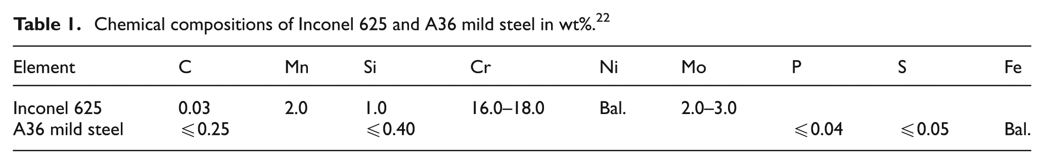
Samples were prepared on A36 mild steel plates with the dimensions of 50 mm × 30 mm × 9.25 mm. The wire was Inconel 625 with a diameter dw of 0.89 mm. The chemical compositions of the substrate A36 and the wire Inconel 625 are listed in Table 1.
Chemical compositions of Inconel 625 and A36 mild steel in wt%. 22
The schematic diagram of LHWC is shown in Figure 1(a). The heat sources in the cladding process included both laser energy and electrical resistance heating. An IPG YLS-4000 fiber laser of a maximum power of 4000 W and a wavelength of 1070 nm was used. A laser beam was guided through an optical fiber of 400 mm in diameter into a laser head equipped with a collimating and focusing lens of 150 mm in focal lengths. The diameter of the focused laser beam was 0.6 mm. The laser head was moved up by 8, 18, and 28 mm to generate a spot size of 2, 4, and 6 mm, respectively. The laser spot size was measured using the Coherent’s beam viewer. First, the scale factor of beam viewer was calibrated. After calibration, a neutral filter was installed. Energy density, beam uniformity, and laser spot size can be recorded. The measurements of spot size were taken by projecting the laser onto the substrate at different defocused distances. The hot-wire system (Jetline, model HWP-50E) consisted of an alternating current (AC) power supply, a wire feeder, and a hot-wire torch with a microprocessor controller. The Inconel 625 wire was fed at an angle β of 55°±°3° to the horizontal direction with a contact-tip-to-substrate distance L of 25 mm ± 2 mm. A hot-wire current loop was formed when the wire contacted the substrate. The current flowed through the wire and the wire was heated up to a soft stage. 19 In order to shield the molten pool from oxidation, argon gas with a flow rate of 10 L/min was supplied coaxially through the wire torch that had an orifice diameter of 12.5 mm. Since the relative position of the laser beam and the wire was fixed, the difference of the wire feeding direction (front and rear) was based on the scanning direction. In the front feeding, the substrate moved along the wire fed direction, as shown in Figure 1(b). In the rear feeding, the substrate moved against the wire fed direction, as shown in Figure 1(c). The tip of the wire was placed at the front, in the center, and at the rear of the molten pool in each feeding direction.
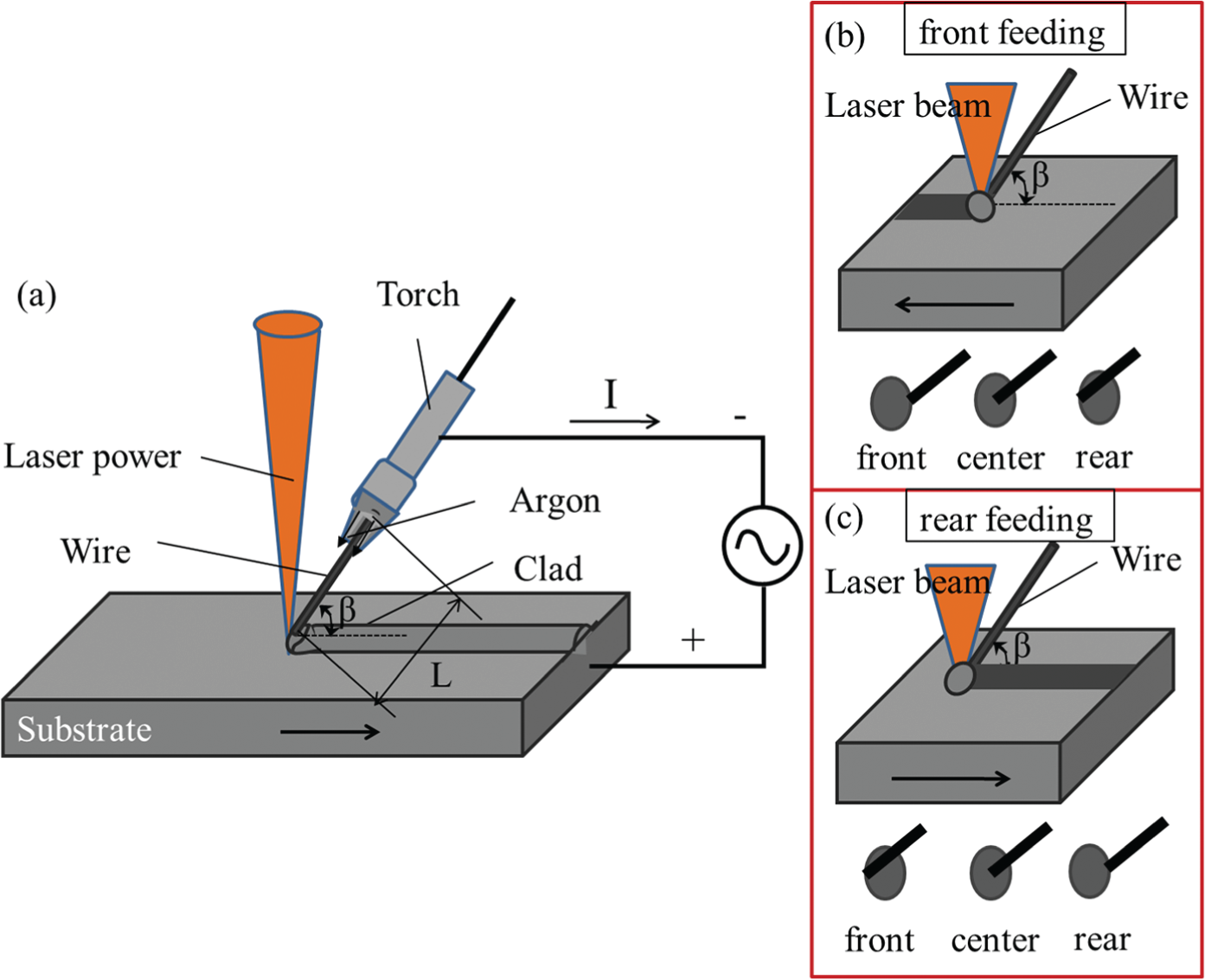
Schematic diagram of (a) the experimental setup for LHWC, (b) front wire feeding, and (c) rear wire feeding.
Single clads were deposited at various processing parameters, and the phenomena of the molten pool behavior during cladding were visually monitored by an in situ observation using a high-speed charge-coupled device (CCD) camera. A 6 W green laser with a wavelength of 532 nm was used to illuminate the molten pool, while a narrow band filter with a wavelength of 532 nm was installed with the optical lens. The images were captured at a frame rate of 250 fps and a shutter speed of 1/500 s.
Experimental procedures
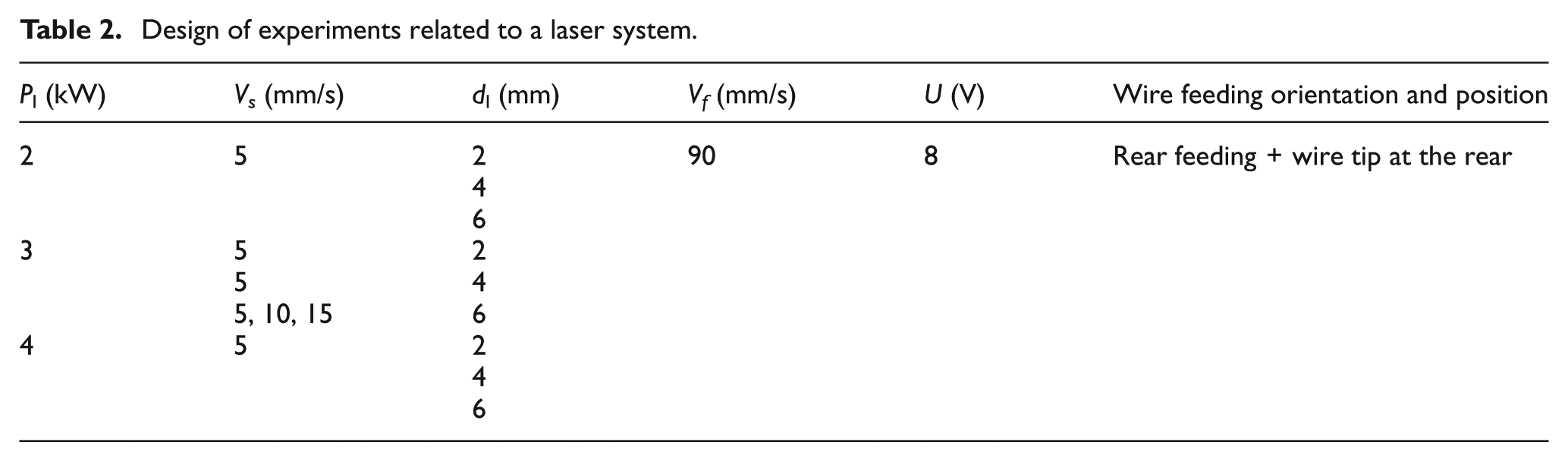
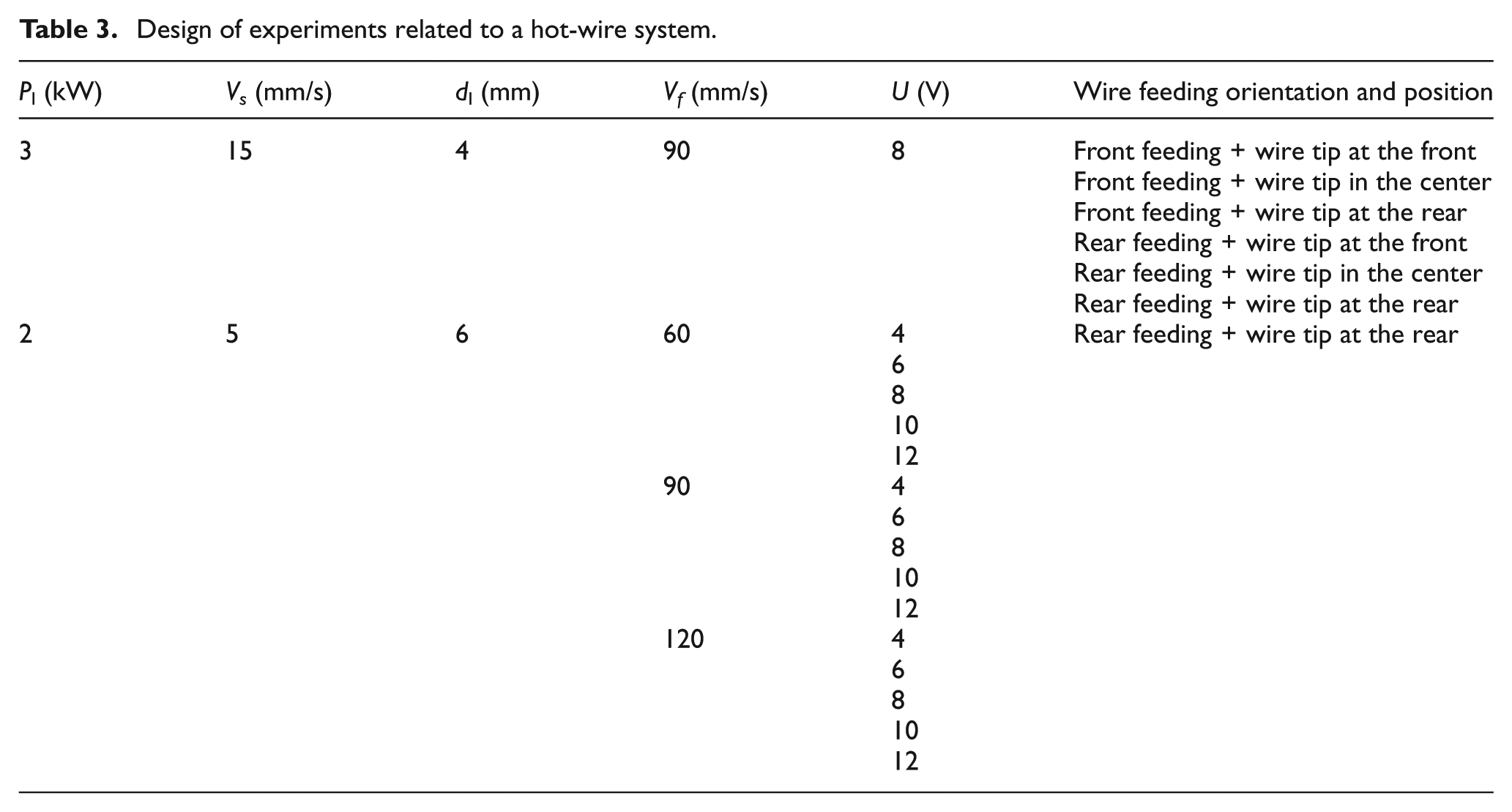
At first, the comparison of LCWC and LHWC was made with respect to the deposition rate, microstructure, and hardness distribution. Optimization of the LHWC processing parameters could be divided into two stages. The first stage of the parameters was dealing with the laser system. The effects of P l, d l, and Vs were investigated, while keeping the hot-wire processing parameters constant: Vf = 90 mm/s, U = 8 V, and rear feeding with the wire tip at the rear of the molten pool, as listed in Table 2. The second stage of the parameter development was related to the hot-wire system. The effects of wire feeding orientation and position were investigated, with the parameters of P l = 3 kW, d l = 4 mm, Vs = 15 mm/s, U = 8 V, and Vf = 90 mm/s. The wire feeding rate Vf and applied voltage U were investigated, while keeping the laser processing parameters constant: laser power P l = 2 kW, laser spot size d l = 6 mm, and laser scanning speed Vs = 5 mm/s, as listed in Table 3. The laser system and hot-wire system were considered to be independent of each other. The optimized parameters were selected to deposit multi-track clads with an efficient overlap ratio.
Design of experiments related to a laser system.
Design of experiments related to a hot-wire system.
In order to reveal the microstructure of the clad, the specimens were cut along the cross section, mounted in epoxy resin, etched by 10% HNO3, and then examined under an optical microscope (OM). The hardness profile of the clad was measured using a Vickers hardness tester with a load of 0.2 kg and a loading time of 15 s. The cross-sectional profile of the clad was measured by a Nanovea profilometer.
Definition of terms
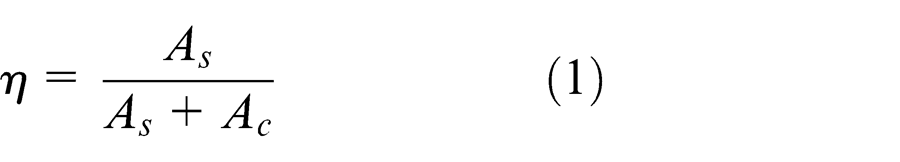
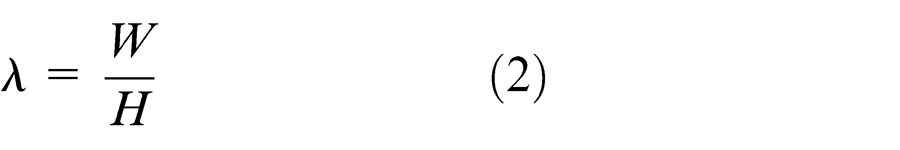
The schematic geometry of a typical single clad is shown in Figure 2. It is defined by its height H, depth D, width W, and contact angle α. The dilution ratio η is defined as a ratio between the penetration area (As ) and the total fusion area (As + Ac ) in equation (1). 20 The geometrical parameters of the clad include the width-to-height aspect ratio λ, which are defined by equation (2) 20
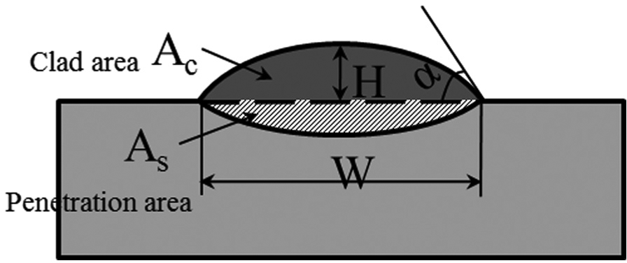
Schematic diagram of the single clad geometry.
The heating power of the wire Inconel 625 Pw is described by Ohm’s law
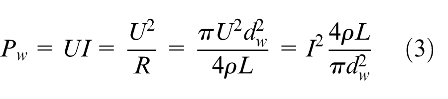
where ρ is the resistivity of Inconel 625, L is the stick-out distance, and dw is the diameter of the wire.
Results and discussion
Comparison between LCWC and LHWC
Cold wire means that there is no preheating of the wire before cladding. The cold wire and hot wire were deposited under the same experimental conditions: the laser spot diameter d l = 4 mm, laser power P l = 3 kW, laser scanning speed Vs = 15–20 mm/s, wire feeding rate Vf = 60–120 mm/s, and the rear feeding with the wire tip at the rear of the laser beam. The surface appearance and the cross section of the clads are listed in Table 4.
Cross sections of the hot-wire and cold-wire clad at varied laser scanning speeds and wire feeding rates.
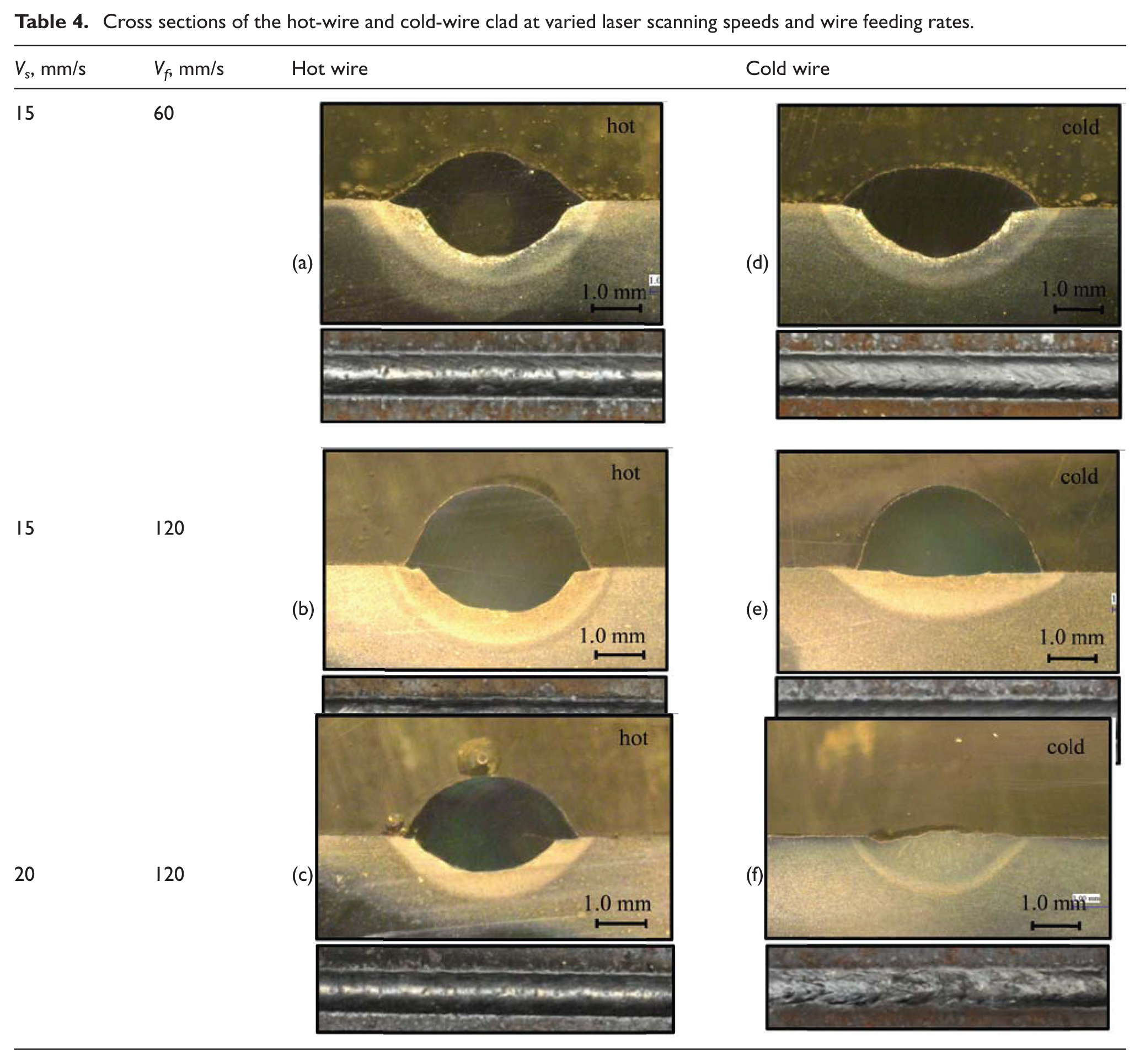
At the wire feeding rate Vf = 60 mm/s and the scanning speed Vs = 15 mm/s, both the cold wire and the hot wire could be deposited on the substrate. In the LHWC process, due to the resistance heating of the wire, which brings more energy into the puddle, which was beneficial for the convection of the molten pool. As a result, the clad appeared smoother and glossier compared to the clad deposited by cold wire. When the wire feeding rate Vf was increased to 120 mm/s, for the LCWC the filler material absorbed a large amount of energy from the molten pool. As a result, the melting depth into the substrate was small, which indicated that the laser energy had reached the critical value to melt the wire and bond it onto the substrate. Whereas for the LHWC, the melting depth was only decreased when the wire feed rate Vf was increased from 60 to 120 mm/s. This result indicates that the primary energy source for melting the material was supplied by the resistance heat. When the scanning speed Vs was increased to 20 mm/s, for the LCWC the laser energy per unit length was decreased. The laser energy was sufficient to melt the wire. The wire was very stiff and was pushed back by the substrate surface. Consequently, the wire stuck out from the molten pool and the deposition failed, as shown in Figure 3. The solution was either to increase the laser power or decrease the deposition rate, neither of which was desirable. However, for the LHWC case, there was still room to increase the scanning speed or wire feeding rate.
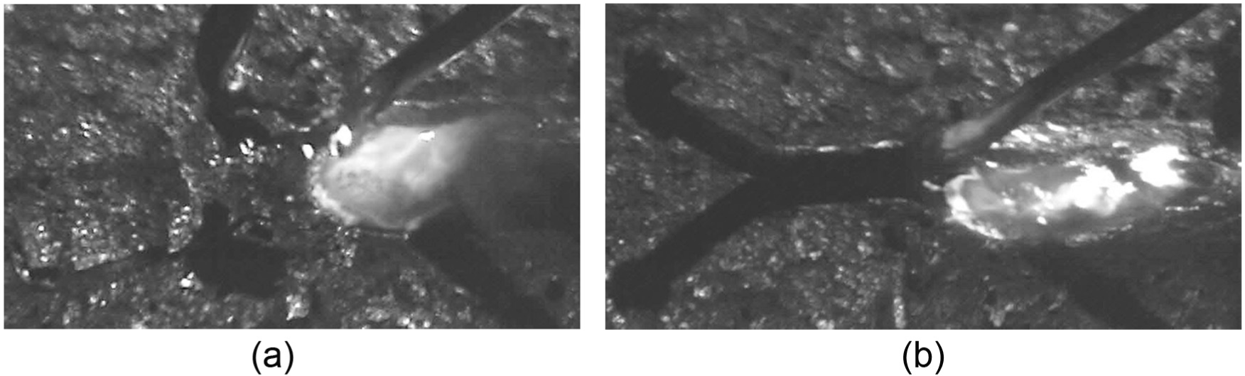
Failure of the cold-wire deposition at (a) t = 2 s and (b) t = 2.2 s.
The microstructure and hardness of LHWC and LCWC deposited clads were also studied. The area marked with a dash-line square shown in Table 4(b) (hot-wire cladding) and Table 4(e) (cold-wire cladding) was selected for the analyses. The microstructure in LHWC clad was dendritic structure with primary and secondary arms, while the microstructure in LCWC clad was slimmer with primary arm, as shown in Figure 4. Due to the extra energy brought into the molten pool by resistance heating in the LHWC, the solidification rate was lower than in the LCWC process. As a result, the hot-wire clad had a coarser microstructure. Combining with the effect of the high dilution in LHWC, in consequence, the hardness in the hot-wire clad (about 230 HV0.2) was lower than in the cold-wire clad (about 260 HV0.2), as shown in Figure 5. The maximum hardness was located in the heat-affected zone, which was about 420 HV0.2 for the hot-wire clad and about 440 HV0.2 for the cold-wire clad.
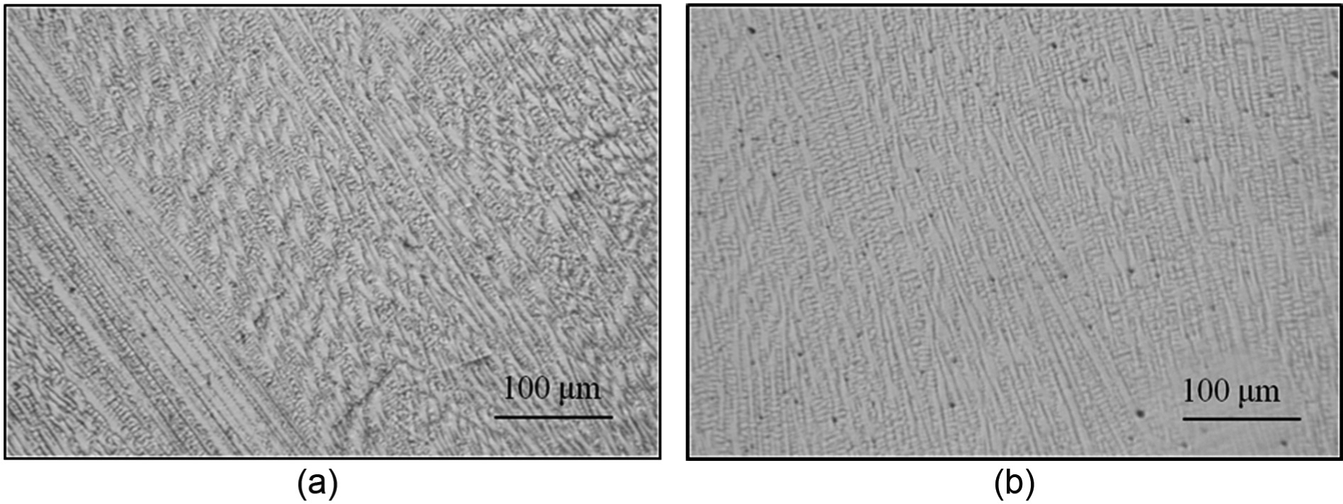
Microstructure of (a) hot-wire cladding and (b) cold-wire cladding.
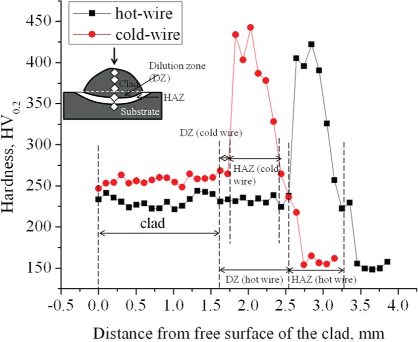
Hardness distribution along vertical centerline.
Optimization of laser hot-wire processing parameters
A primary objective of the parameter optimization of LHWC was to stabilize the deposition process and achieve porosity-free layers with smooth surfaces and low dilution. In addition, due to the requirement of producing a consistent clad over a large area with a required thickness, the single clad usually needed to have a suitable shape in order to provide a smooth overlapping. The aspect ratio (W/H) and the contact angle α (see Figure 2) played an important role in determining the subsequent deposition without porosity. 20
Optimization of laser processing parameters
In order to study the effects of laser processing parameters, 11 experiments were performed according to Table 2, with a variation in laser spot size d l from 2 to 6 mm, scanning speed Vs from 5 to 15 mm/s, laser power P from 2 to 4 kW, and rear feeding with the wire tip at the center of laser beam. Among the laser processing parameters, the laser spot size had the most significant impact on the quality of the clad, as shown in Figure 6. The power density was extremely high for a small laser spot size and the molten pool was too narrow to absorb the amount of feeding material. As a result, a clad with a nearly spherical shape and a large penetration depth was formed. Although the laser power density could be effectively decreased by increasing the scanning speed, the quality of the deposited clad was low due to the low fluidity of the molten wire. Enlarging the laser spot by defocusing the laser beam could be used to widen the track, which decreased the laser power density and improved the capacity to form a robust molten pool.
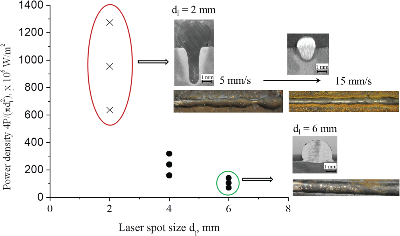
Power intensity at different laser spot sizes and power levels.
At laser spot size d l = 6 mm, the effects of laser power P and scanning speed Vs on the dilution ratio were investigated. Figure 7(a) shows that the dilution ratio increased with the laser power. Due to the characteristics of LHWC, the melting of the substrate was mainly done by the laser beam. Therefore, when the laser power was increased, more substrate material was melted, resulting in a higher dilution.
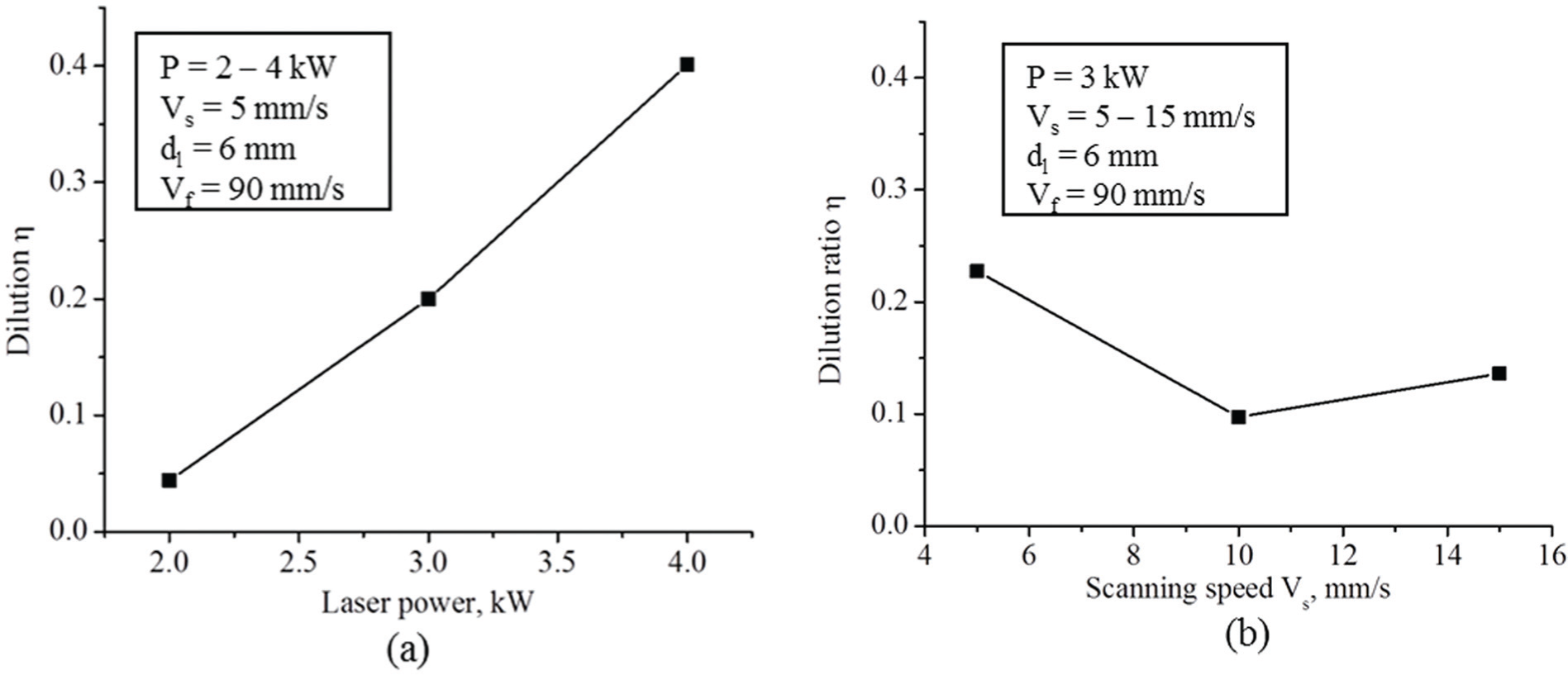
Dilution ratios with respect to (a) laser power and (b) scanning speed.
Figure 7(b) shows the variation of dilution ratio η versus the laser scanning speed Vs at laser power P = 3 kW. The dilution ratio first decreased with an increase in the laser scanning speed Vs from 5 to 10 mm/s and then increased with an increase in the scanning speed. As Vs was increased, the energy per unit length (P/Vs ) and the deposition volume per unit length (Vf /Vs ) were decreased. The reduced energy per unit length generated the shallower molten pool into the substrate. The reduced deposition volume per unit length produced a clad with a lower height. The dilution ratio indicated the relative change between the melting area into the substrate and the total fusion area. When Vs was increased from 5 to 10 mm/s, the reduction in the penetration area from 3.82 to 0.8 mm2 was more significant than the reduction in the total fusion area from 16.62 to 7.15 mm2, resulting in a decreased dilution ratio. When Vs kept increasing to 15 mm/s, the change in the clad area became more dominant (the penetration area is 0.65 mm2 and the total fusion area is 4.16 mm2), resulting in an increase in the dilution ratio. With the variation in laser power (2–4 kW) and laser scanning speed (5–15 mm/s), the dilution ratio changed from 0.05 to 0.4.
Optimization of hot-wire processing parameters
Through our experimental work on the LHWC, the wire feeding orientation and position were investigated as one of the critical factors for a successful deposition. The effect of wire feeding orientation (front and rear feeding, seen in Figure 1(b) and (c)) and its corresponding wire tip position regard to the molten pool (front, middle and rear) were investigated. There were six experiments performed as presented in Table 3. The molten pool images with the consequent clad images are shown in Figure 8.
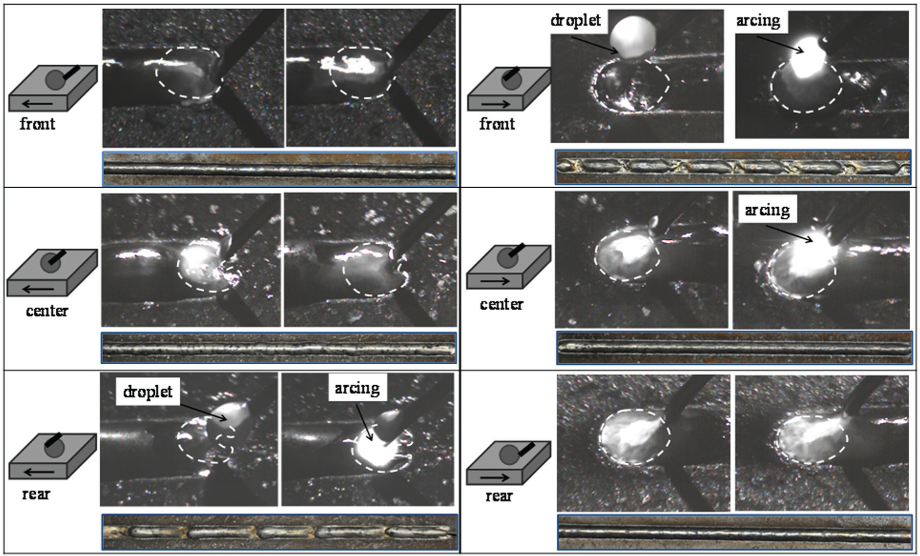
Front feeding orientation with wire tip (a) at the front, (b) in the middle, (c) at the rear of the molten pool and rear feeding orientation with wire tip (d) at the front, (e) in the middle and (f) at the rear of the molten pool.
For the wire front feeding, in Figure 8(a), the wire tip was placed in front of the molten pool. There was no intersection of the laser beam with the filler wire. A smooth clad was obtained. However, the tolerance of the wire tip position in this situation was very narrow. Any disturbance, which might have caused the wire to move away from the front of the molten pool edge or to draw closer to the center of the molten pool, would have resulted in an unstable or even failed deposition. In Figure 8(b) and (c), it could be seen that there was an indentation in the rear of the molten pool because of the shading effect of the laterally fed wire from the laser beam. The presence of the wire under the laser beam not only affected the full development of the molten pool but also reflected a considerable part of the laser energy. 23 In Figure 8(b), although part of the upper surface of the wire tip was melted by the laser beam, the continuous contact with the molten pool ensured a continuous flow of current without arcing. However, the clad width was not uniform. The reason for the non-uniform clad was that the fluid flow in the molten pool was not well developed and was unstable. In Figure 8(c), the wire tip was completely melted by the laser beam, and the conductive contact between the wire and the molten pool was interrupted, resulting in arcing and discontinuous transferring of the filler material.
In the wire rear orientation, for Figure 8(d), the wire tip crossed the laser beam and was positioned in front of the laser spot. The tip of the wire was melted. The droplets were created periodically and the arc was generated, causing spatters and a discontinuous clad. In Figure 8(e), the wire tip was placed in the middle of the laser spot. The intersection of the wire with the laser beam did not affect the full development of the molten pool. Due to the high temperature at the rear of the molten pool and the irradiation of the laser beam, the wire tip was melted and the arcing occurred. Regardless, a clad with a smooth surface was still obtained. In Figure 8(f), the wire tip was placed at the rear of the laser spot. There was no intersection between the laser beam and the wire. The laser beam created a molten pool, and the molten wire smoothly flowed into the molten pool, producing a clad with a smooth surface. The wire was in contact with the molten pool during the entire process, and the transfer of material was very steady. Since there was a long trail of the molten pool, a small displacement of the wire tip did not affect the stability of the deposition process.
In order to ensure a closed loop of hot-wire current, continuous conductive contact between the wire and the substrate is necessary. A stable and fully developed molten pool is required for a uniform clad. The intersection of the wire with laser beam should be minimized and the tolerance against the disturbance of the wire tip position should be enlarged. Therefore, the rear wire feeding orientation with the wire tip at the rear of the molten pool was considered as the best wire feeding orientation and position in the LHWC process.
In the LHWC process, arcing occurred occasionally and should be avoided. The arc was much hotter than the resistance heat. It generated a large amount of spatters, excessively melted the substrate material into the clad, and affected the stability of the cladding process. As per Table 3, 15 experiments were performed with the applied voltage U from 4 to 12 V and a wire feeding rate Vf from 60 to 120 mm/s. Figure 9 shows the recorded profiles of the applied voltage U and the corresponding current I at Vf = 90 mm/s at a sampling frequency of 20 Hz. It was found that the current fluctuated strongly when the voltage exceeded 8 V, which indicated instability in the cladding process. The reason for this result was that the wire was melted at a high voltage, forming a gap between the wire tip and the substrate and a large step-change increase in resistance. The current from the power supply system continued to flow in an attempt to remain at constant voltage and resulted in generation of an arc. According to Ohm’s law in equation (3), the heating power depends on the current and the wire resistance. Since the resistance of Inconel 625 was only slightly changed by the increase in temperature, the calculated current changed almost linearly with the applied voltage, which was also reported by Nurminen et al. 8 Figure 10 shows the calculated current at different applied voltages, with the assumption of the mean wire temperature of 1000 K. 8 However, the measured current stayed around 85 A when the voltage was larger than 8 V. Peters 19 noted that the current decreased even when the voltage exceeded the threshold value. The reason for this result could be explained by the formation of a gap between the wire tip and the substrate at high voltage, which contributed primarily to the circuit resistance.
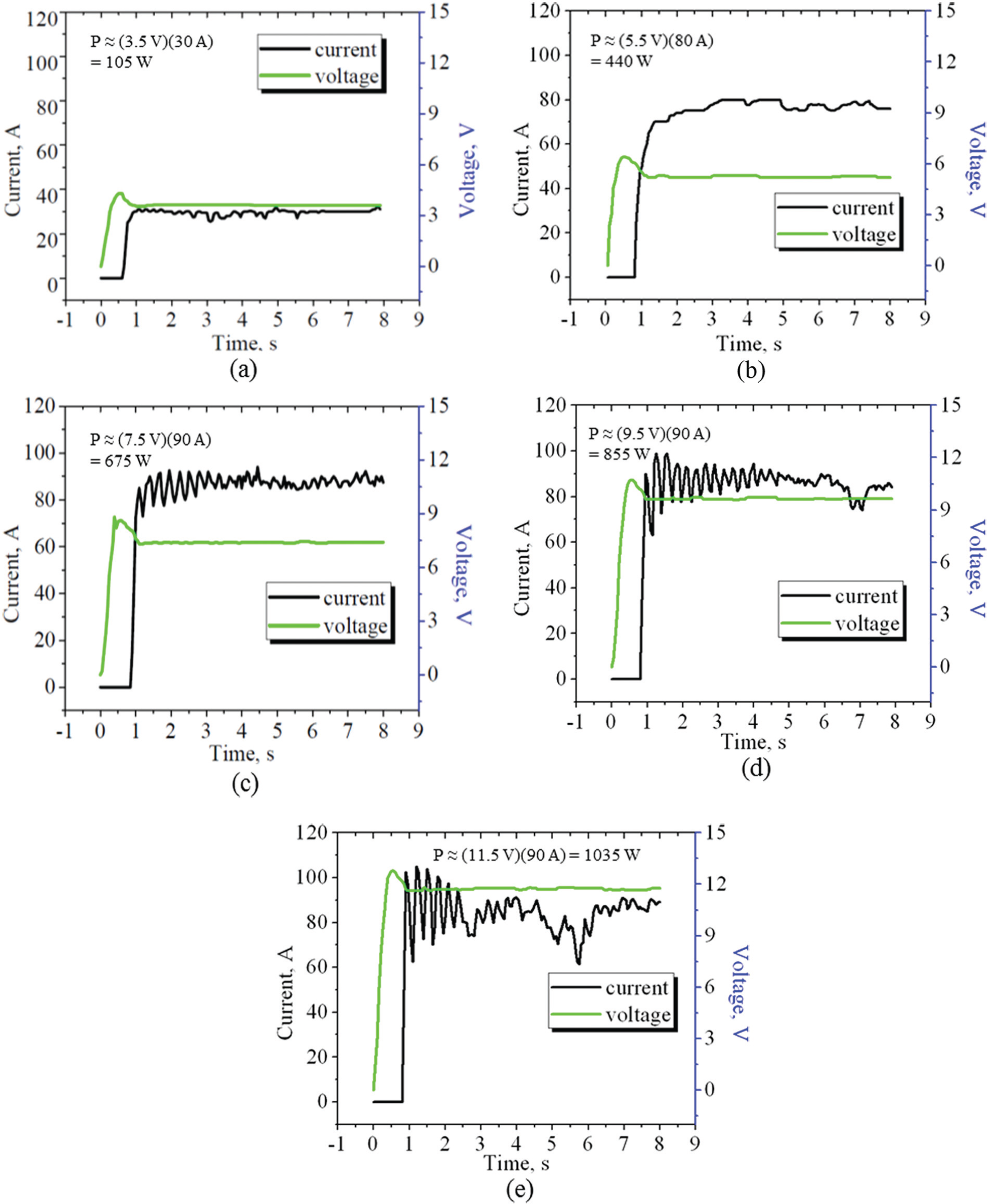
Recorded profiles of current as a function of the applied voltage of (a) U = 4 V, (b) U = 6 V, (c) U = 8 V, (d) U = 10 V, and (e) U = 12 V.
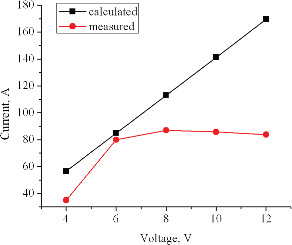
Calculated and measured currents at different voltages.
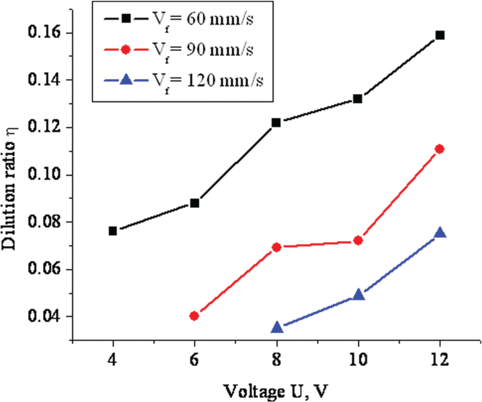
The generate rate of the resistance heat in the wire
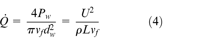
In order to supply an adequate heat, the applied voltage must be increased with the wire feeding rate. A desirable range of the applied voltage at different wire feeding rates was interpolated and plotted in Figure 11. At a given wire feeding rate, when the applied voltage exceeded the upper limit, the generated arc affected the stability of the process and consequently decreased the clad quality. However, at the voltage below the down limit, the energy was not sufficient to preheat the wire high enough before it entered the molten pool, causing wire stubbing or glancing off the substrate.
Desirable voltage range at different wire feeding rates.
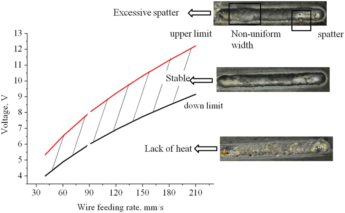
At the experimental conditions P = 2 kW, Vs = 5 mm/s, d l = 6 mm, and rear feeding with wire tip at the rear of the molten pool, the dilution ratio η, the width-to-height aspect ratio λ, and the contact angle α were investigated at varied voltages and wire feeding rates. Figure 12 shows that the dilution ratio η was increased with the applied voltage U and decreased with the wire feeding rate Vf . The increased voltage generated more heat by resistance, and this heat was conducted into the substrate. At an increased wire feeding rate, more material was deposited onto the substrate, resulting in a decrease in the dilution ratio. With the variations in the wire preheating voltage (4–12 V) and the wire feeding rate (60–120 mm/s), the dilution ratio changed from 0.01 to 0.1. The laser processing parameters had a more significant influence on the dilution ratio than the hot-wire processing parameters.
Variation in dilution ratios with the main hot-wire processing parameters.
The width-to-height aspect ratio λ of the deposited clad was calculated from the measured clad width and height. Figure 13 shows that the aspect ratio λ increased with the voltage U and decreased with the wire feeding rate Vf . The higher voltage generated more heat by resistance and arcing and decreased the viscosity of the molten pool. This enhanced the spreading of the filler material. Consequently, the clad width increased and the clad height decreased, resulting in a higher aspect ratio. The increase in the wire feeding rate mainly built up the height of the clad, which lead to a lower aspect ratio.
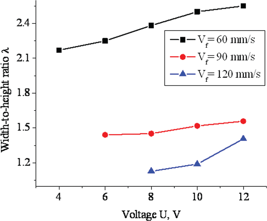
Variation in width-to-height ratios with the main hot-wire processing parameters.
Figure 14 shows that the contact angle α decreased with the voltage U and increased with the wire feeding rate Vf . As mentioned before, the higher voltage improved the fluidity of the molten pool and it was easier for the deposited material to be spread over the substrate surface. At a lower deposition rate, the clad was formed with a contact angle smaller than 90°. At a higher wire feeding rate, the clad was approaching a spherical shape, which was characterized by a higher contact angle.
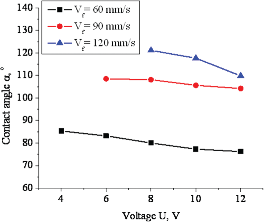
Variation in contact angle with the main hot-wire processing parameters.
Multi-track deposition
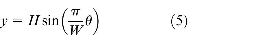
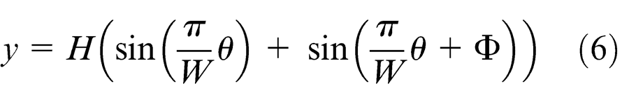
In order to produce a large clad area with the required thickness, the single-track clad has to be repeated and overlapped with a certain increment. Desirable conditions for a multi-track deposition are a clad with good surface quality, low contact angle (<80°) 24 and low dilution ratio (≤0.1). 25 According to the above discussion, the optimal processing parameters of LHWC were as follows: P = 2 kW, Vs = 5 mm/s, d l =6 mm, Vf = 60 mm/s, U = 8 V, and rear feeding with wire tip at the rear of the molten pool. To achieve a smooth multi-track, the overlapped area is desired to be close to the concave area of the adjacent tracks. The surface profile of the single clad measured by the profilometer shown in Figure 15(a) could be approximated by a sinusoid, which is described by equation (5)
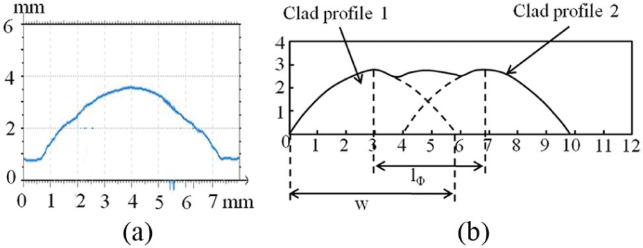
(a) Measured profile of the single clad. (b) Schematic diagram of the profile of the overlapped clads. 26
where θ is the phase of the sinusoid.
The sinusoid function describing the profile of the adjacent clad is given as
where Φ is the equivalent phase difference maintained between the two adjacent clads. The Φ could be determined by 26
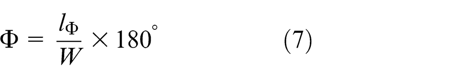
where l Φ is the distance between the adjacent clads, as shown in Figure 15(b).
The overlap profiles of double-tracks with overlap ratios of 20%, 30%, and 40% are plotted in Figure 16(a)–(c), respectively. It shows that at overlap ratios of 20% and 30%, the overlapping area was too small to compensate for the deficit, while an overlap ratio of 40% was too much. Therefore, the optical overlap ratio should be between 30% and 40%. In the experiments, the overlap ratio of 35%, where the equivalent phase Φ was 117°, could provide the smoothest surface for the clad. Therefore, a sound clad with an area of 35 mm × 35 mm was deposited with an overlap ratio of 35%. Its appearance and cross section are shown in Figure 17.
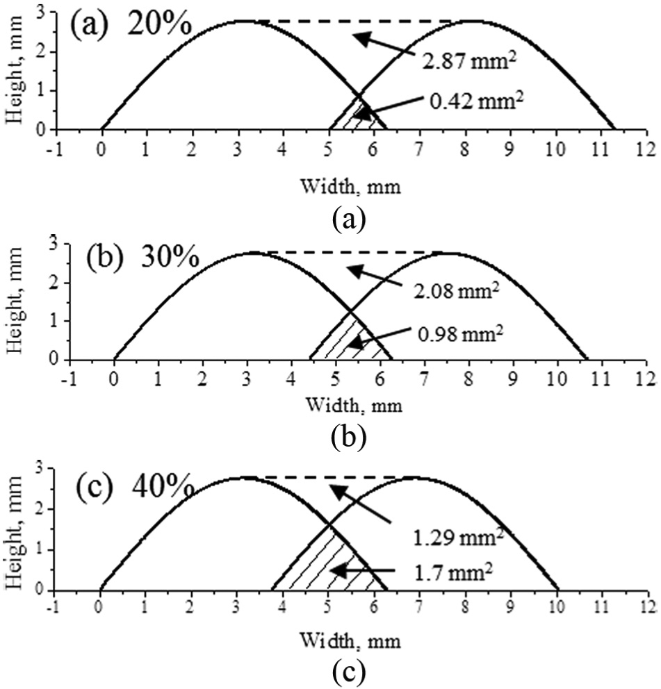
Overlap profile with overlap ratios of (a) 20%, (b) 30%, and (c) 40%.
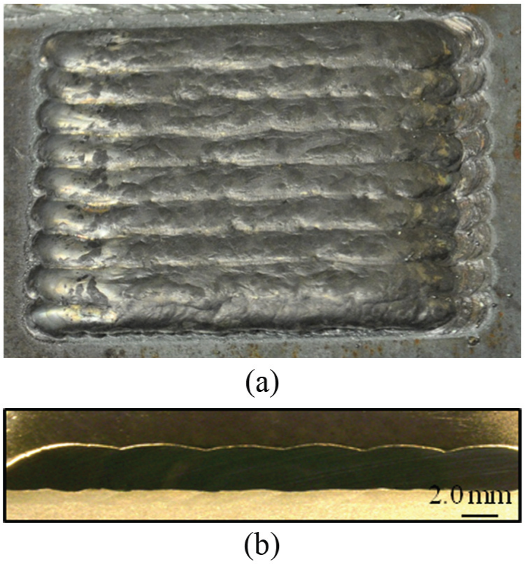
Multi-track: (a) clad appearance and (b) cross section.
Conclusion
In this study, the LHWC technique was used to deposit Inconel 625 on A36 mild steel. In LHWC, the wire was heated by resistance and the laser was used to create a molten pool for fusing the wire material on the substrate. The effects of different processing parameters on the clad characteristics were investigated.
Several conclusions could be drawn as follows:
Compared to the LCWC, preheating of the wire by resistance reduced required laser power. With the same processing parameters, the microstructure of the clad by LHWC was coarser than the clad by LCWC. As a consequence, the hardness of the clad by LHWC was lower. The high dilution may also contribute to the lower hardness of the clad by LHWC.
Among the laser processing parameters, the laser spot size had the most significant impact on the clad quality. A larger laser spot size was beneficial for obtaining a sound clad at a higher deposition rate. The dilution ratio was increased with laser power. The effect of laser scanning speed on the dilution ratio was not linear, depending on the relative change of the laser energy per length and the deposition volume per length. Laser processing parameters had more significant influence on the dilution ratio than hot-wire processing parameters.
In the LHWC process, the wire feeding orientation and the wire tip position regard to the molten pool were the critical parameters in the LHWC. A continuous conductive contact between the wire and the molten pool was necessary, and a full and stable development of the molten pool was required. It was found that the rear wire feeding with the wire tip placed at the rear of the molten pool is the optimal position.
The applied voltage should prevent arcing but also be high enough to heat the wire near its melting temperature. The strong fluctuation of the current indicated the instability of the process at a high voltage. The generated arcing caused excessive spatters and affected the clad quality. The applied voltage should be increased proportionally to the wire feeding rate in order to supply adequate resistance heating.
The width-to-height ratio increased with an increase in the voltage, but decreased with an increase in the wire feeding rate. The contact angle decreased with an increase in the applied voltage, while increased with an increase in the wire feeding rate.
A desirable single clad was obtained by the optimized processing parameters, which had low contact angle, low dilution ratio, and high surface quality. A sound multi-track clad with an optimal overlap ratio of 30% was achieved.
Footnotes
Acknowledgements
The authors would like to thank Andew Socha in the Center for Laser Aided Manufacturing for the help in the execution of experiments.
Declaration of conflicting interests
The author(s) declared no potential conflicts of interest with respect to the research, authorship, and/or publication of this article.
Funding
The author(s) disclosed receipt of the following financial support for the research, authorship, and/or publication of this article: This work was funded by the NSF Grant No. IIP-1034652.