
Abstract
One possible way of preventing excessive growth of smearings/loads on the grinding wheel active surface is the introduction of compounds such as sulfur, graphite, or wax into the grinding wheel volume which exerts an active influence on adhesion during the process of impregnation. Limiting the formation of smearings/loads on the grinding wheel active surface is of crucial importance to achieve effective grinding of hard-to-cut materials (such as nickel superalloys) which are characterized by considerable ductility and a strong chemical affinity to abrasive grains, among other things. This article presents the results of experimental tests performed on plunge grinding and the influence of sulfur impregnation of grinding wheels on the smearing/load intensity on the grinding wheel active surface during the process of internal cylindrical plunge grinding of openings made from Inconel® alloy 600 and Incoloy® alloy 800HT®. Bearing steel 100Cr6 was included in the tests as a reference material. Grinding wheels were impregnated with a new method of gravitational sulfurization combined with centrifuging. The experiments carried out show that the adhesive properties of sulfur allowed for considerable limitation of smearing/loading of the grinding wheel active surface with machined material. This mainly concerned limiting the formation of the largest and most technologically undesirable smearings/loads of the intergranular spaces. The presence of sulfur in the grinding wheel volume had a minor influence on the intensity of smearings/loads in the microareas of the active abrasive grains’ apexes. The tests also showed an increase of 32%–49% in the value of parameter Sa in the surfaces ground with grinding wheels impregnated with sulfur for all the examined materials.
Keywords
Introduction
Modern construction materials used in the automotive, aviation, and chemical industries are characterized by high durability, low specific gravity, resistance to corrosion, and high temperatures, as well as high ductility. These materials often consist of superalloys of nickel such as Inconel®, Incoloy®, Brightray®, Nimonic®, Monel®, Udimet®, Nilo®, Hastelloy®, and Waspalloy®, which are described as hard-to-cut materials because of their high durability and ductility, low heat conductivity, high chemical affinity in relation to machining tools, and high values of friction coefficients.1–5
The research carried out aimed at increasing the effectiveness of machining these alloys and mainly concerned the cutting processes that use single- or multiple-blade tools. As a result, a special construction of drills and lathe shank and shaping tools was developed. There was also considerable improvement in the optimization of machining parameters, selection of coolants, and construction of cutting machines and technological devices.
Only a small amount of research is dedicated to the machining of hard-to-cut materials via grinding. This is due to the high complexity of phenomena taking place in the contact area between the grinding wheel (with an unidentified geometry) and the machined material. The high ductility and strong chemical affinity of the nickel superalloys cause intensive smearing/loading of the grinding wheel active surfaces (GWASs). Low heat conductivity causes large temperature increases in the machining zone, which results in greater intensity of heat-fatigue wear of abrasive grains and bond bridges. Susceptibility to the heat-induced increase in durability and hardness has a negative effect on the abrasive and fracture wear of the active abrasive grains.6–12
One of the ways of preventing excessive growth of smears/loads on the GWAS is the introduction of compounds such as sulfur, graphite, or wax into the grinding wheel volume during the process of impregnation that has an active influence on adhesion. Limiting the phenomenon of GWAS smearing/loading positively influences the amount of heat released during the grinding process, thus limiting the participation of friction.
The antiadhesive properties of sulfur have first been used to exert an active influence upon the conditions in the grinding zone as early as the 1920s.13–16 Currently, various sulfur compounds are added to machining liquids17–22 and used to impregnate grinding wheels, on which it also decreases the shape wear (of most of the profiled wheels).23–27
Application of methods known from the literature13–16,28 of sulfurizing grinding wheels in gravitational or elevated pressure conditions often causes uneven distribution of sulfur in the grinding wheel volume and complete filling of the free intergranular spaces. This is a considerable limitation in the case of processes for grinding of hard-to-cut materials, in which the grinding wheel porosity plays a crucial role. The free intergranular spaces transport long and ductile chips, as well as products of grinding wheel wear, outside the area of contact between the grinding wheel and the machined material. They also exert a positive influence upon the provision of coolant into the grinding zone. Impregnating large-pore grinding wheels, adjusted to the requirements of grinding hard-to-cut materials, in a traditional way causes smaller openness in the GWAS structure. For this reason, efforts were made to modify the known methods of sulfurization in order to effectively introduce the impregnate while maintaining the grinding wheel porosity.
Sulfurization of the grinding wheels
In the developed method of impregnation of the grinding wheels with ceramic bond, fluid sulfur was gravitationally introduced into the grinding wheel volume and its excess removed by centrifuging (Figure 1).
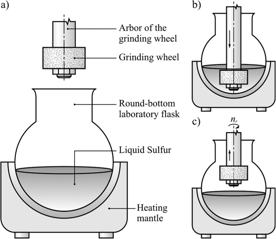
Schematic diagram of the experimental setup for sulfurization of grinding wheels: (a) main elements of the setup, (b) position during sulfurization stage, and (c) position during centrifugation stage.
The sulfurization procedure was carried out in the following stages:
Drying the grinding wheel to eliminate the presence of water;
Heating the sulfur up to temperatures ranging from 120 °C (393 K) to 160 °C (433 K), at which point sulfur becomes fluid (Figure 1(a));
Immersing the grinding wheel in fluid sulfur for 10 min in order to warm up the grinding wheel and get a uniform sulfur temperature in the whole volume, which guarantees its even penetration into the grinding wheel pores (Figure 1(b));
Lifting the grinding wheel above the liquid sulfur surface and centrifuging the sulfur excess with speed nr = 1200/min, during tr = 3 min (Figure 1(c));
Cooling the grinding wheel for the impregnate to congeal.
The final impregnate volume can be influenced and the grinding wheel porosity can be regulated by changing the parameters of the final centrifugation (centrifuging speed nr and centrifuging time tr ).
Figure 2 presents a comparison of the GWAS microscopic views before (Figure 2(a)) and after the sulfurization process (Figure 2(b)). The most important difference, visible after comparison of the microscopic images of the non-sulfurized GWAS (Figure 2(a)) and the sulfurized one (Figure 2(b)), is the considerable volume of sulfur on the grinding wheel surface and the limiting of the volume of free intergranular spaces. The open structure of the grinding wheel visible in Figure 2(a) guarantees an even distribution of sulfur throughout the whole volume of the tool.
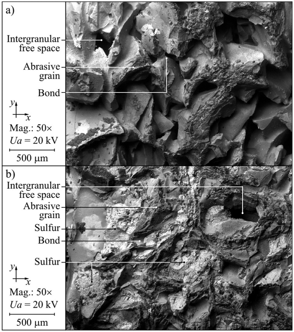
SEM microphotography of the grinding wheel active surface made of microcrystalline sintered corundum grain size 46: (a) before sulfurization and (b) after sulfurization with marked areas of visible sulfur.
Such a solution guarantees the delivery of sulfur directly into the area of contact between the grinding wheel and the machined material. The considerable openness of the structure of the grinding wheel used in the tests made it possible for the impregnate to penetrate the whole volume of the tool. As a result, the procedures of dressing, sharpening, and profiling of the grinding wheel had no influence on the effective distribution of the impregnate into the area of contact between the grinding wheel and the machined material.
Due to its small size, the examined grinding wheel (described in detail in section “Grinding wheels”) contained 2.62 g of sulfur after the sulfurization process. Such a small amount of sulfur was aimed at decreasing the adhesion of machined material chips to the grinding wheel surface, while not posing a threat to the machining environment.
Methodology of experimental tests
The aim of the experimental tests was to determine the influence of impregnating the grinding wheel with sulfur on the intensity of smear/load creation on the GWAS in the process of internal cylindrical grinding of openings made from Inconel alloy 600 and Incoloy alloy 800HT.
The experiments were carried out in accordance with the methodology for examining the phenomena of wear on the GWAS during the process of plunge grinding described in detail in the literature.29,30 Tests were carried out without repetition due to the large range of analysis of results and the measurements’ workload.
The methodology consists in carrying out a short grinding test which lasts, 3 s, for example, with a specially shaped grinding wheel using the kinematics of plunge grinding (Figure 3).
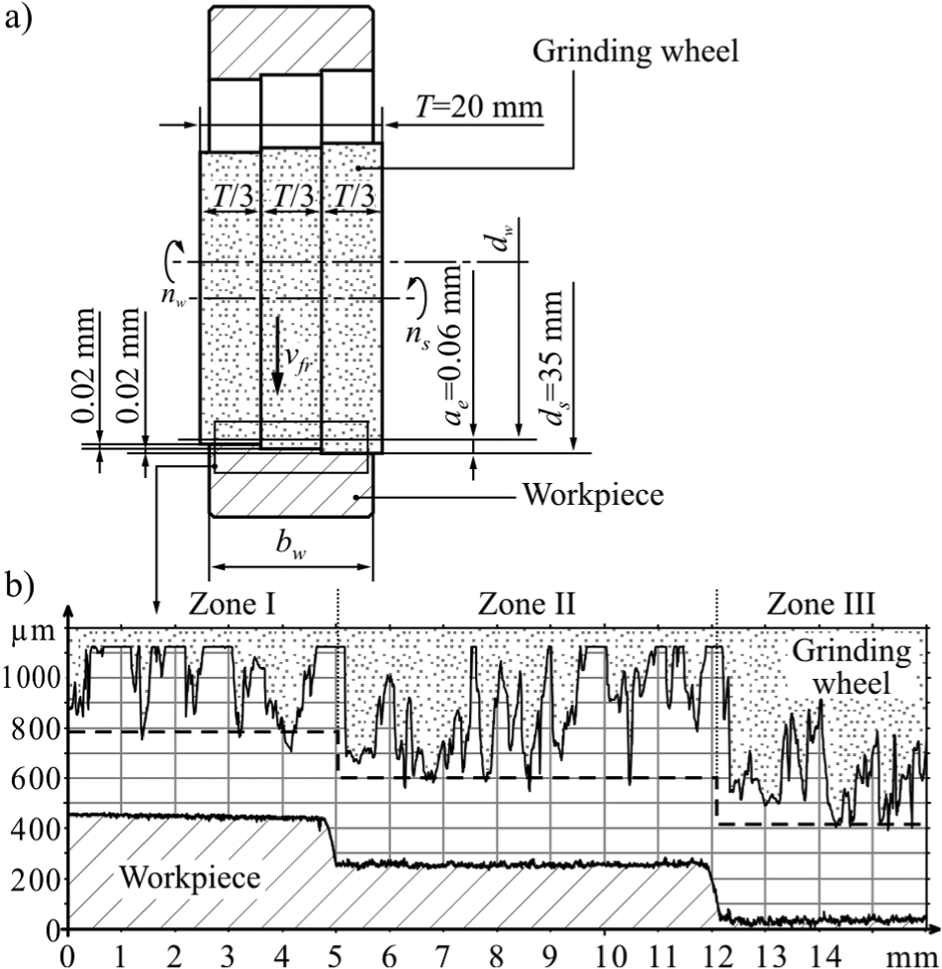
A crucial feature of this method is the omission of the finish grinding and sparking out stage. The grinding wheel performs the working move using the adopted radial (plunge) feed speed vfr , after which it is immediately removed from the machined material. Its goal is to identify as precisely as possible the GWAS wear processes, as well as the processes of material removal, chip formation, creation of material pick-ups, ridging, and so on.
Modification of the grinding wheel geometry applied in the developed method consists in the formation of a few (e.g. three) zones with different diameters in the dressing procedure to obtain a uniform division of T height into particular working zones. The method also assumes that the total machining allowance ae is divided evenly over the subsequent grinding wheel zones.
The special shaping of the grinding wheel macrogeometry makes particular zones of its active surface work at different times and removes different material volume Vw . As a consequence, in particular, GWAS zones the process of abrasive grain and bond wear, and the phenomena of chip formation or smearing/loading of intergranular spaces occur with different intensities and may take on various forms. In a GWAS of such shape occur constant grinding conditions in each zone, and this enables the drawing of more reliable conclusions. Moreover, there is no need to use a special device for precise shaping of the GWAS. Shaping of the zones with various diameters can be done using conventional dressing and conditioning methods.
Applied methodology is particularly useful in assessing the mechanisms of wear of the GWAS that take place during grinding, as well as the various phenomena that cause them. One of the greatest advantages of this method is the fact that a multicriterion assessment of the material removal conditions, resulting from changes to the GWAS load, is possible as a result of a short grinding test. The method also allows comparative tests of grinding wheels with different characteristics and diverse grinding parameters, as well as comparison of various workpieces, as presented in this study.
It should be noted, however, that the analysis workload can be significant when a large number of evaluation criteria are taken into consideration. Moreover, the combination of different depths of cut may cause interference and therefore may lead to biased results.
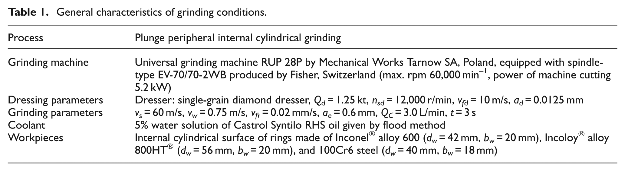
Table 1 includes the detailed conditions of the experimental tests performed on plunge grinding.
General characteristics of grinding conditions.
Grinding wheels
Grinding wheels made of sintered microcrystalline corundum grains of size 46 and glass-crystalline ceramic bond were used in the tests.31–33 Grinding wheels with a technical marking 1-35 × 20 × 10-SG/F46G10VTO characterized by a very open structure were made in the Division of Fundamentals of Material Science and Technical Ceramics in the Institute of Technology and Education at Koszalin University of Technology. The tools underwent the process of impregnation with sulfur in the Division of Applied Chemistry of the Faculty of Mechanical Engineering at the same university. As a result of the sulfurization process, the grinding wheel volume was increased by 10.79%, from 24.28 to 26.90 g. A non-impregnated grinding wheel was included in the tests as reference. Table 2 includes the characteristics of two types of grinding wheels used in the tests: a sulfur treatment grinding wheel (STGW) and a reference grinding wheel (RGW).
Characteristics of grinding wheels used in the experiments.
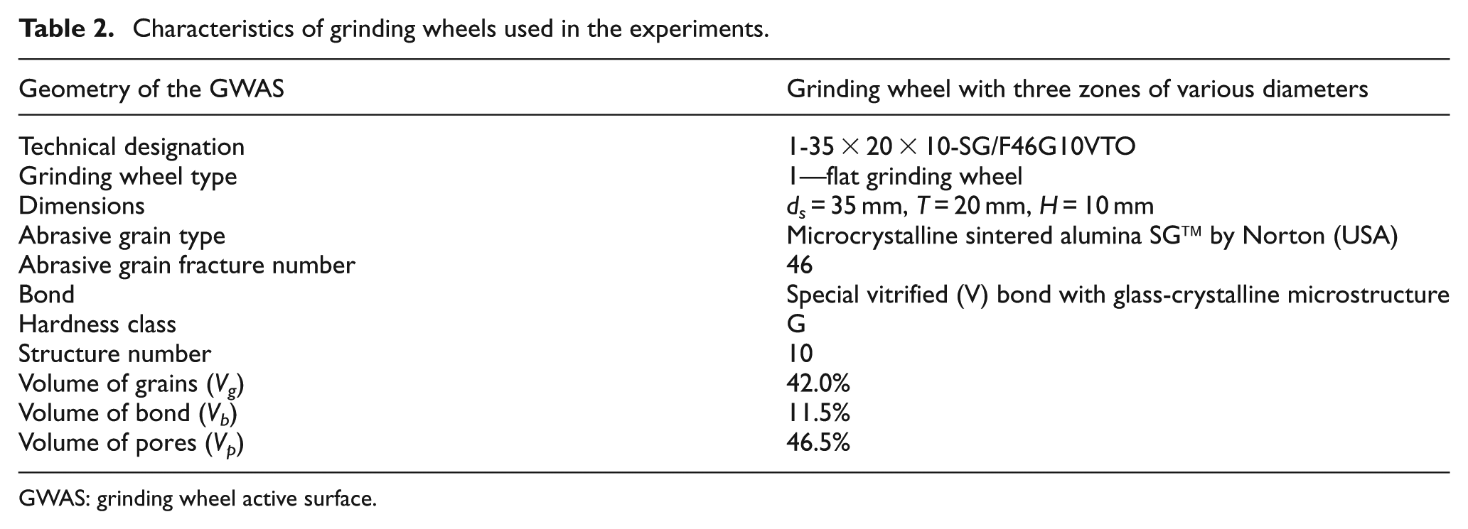
GWAS: grinding wheel active surface.
Characteristics of tested hard-to-cut materials
The grinding tests were carried out on the internal surfaces of rings made from two hard-to-cut materials: Inconel alloy 600 and Incoloy alloy 800HT. Bearing steel 100Cr6 with hardness 62 ± 2 HRC was included in the tests as a referential material. Table 3 includes the characteristics of the ground materials.
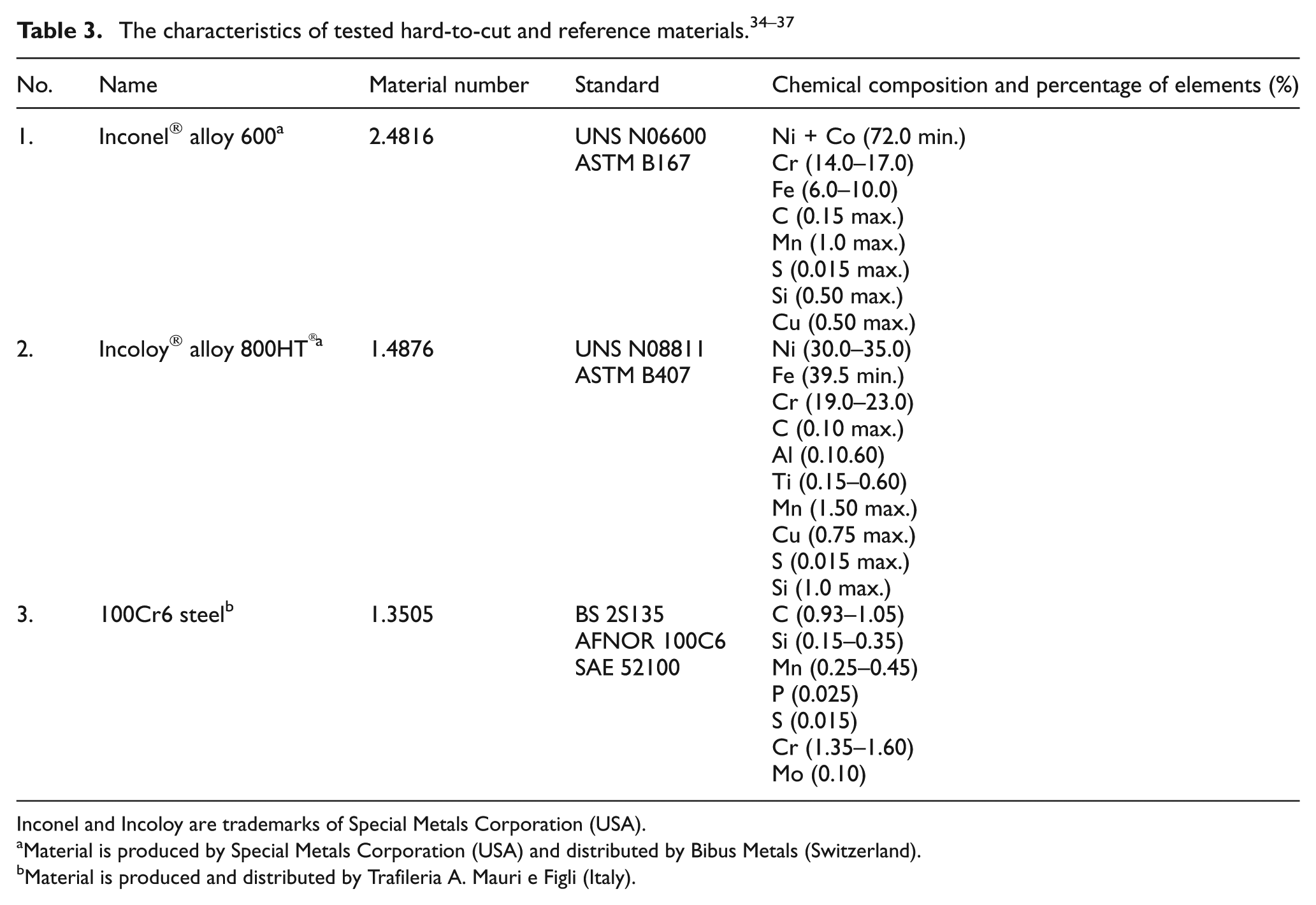
Inconel and Incoloy are trademarks of Special Metals Corporation (USA).
Material is produced by Special Metals Corporation (USA) and distributed by Bibus Metals (Switzerland).
Material is produced and distributed by Trafileria A. Mauri e Figli (Italy).
Inconel and Incoloy belong to the group of superalloys listed on the nickel matrix, which are classified as so-called hard-to-cut materials due to the following reasons:
Great mechanical durability and hardness that contribute to the mechanical wear of cutting tools;
High ductility, which leads to the creation of smearings/loads and accretions on the vertexes of cutting tools;
Low heat conductivity, which causes the temperature increase in the machining zone, which then contributes to the wear of the cutting edges;
Alloy components in the material structure, which are the abrasive components that accelerate the abrasive wear of the blade;
Hardening during their machining.
Inconel alloy 600 is a nickel–chrome alloy with high resistance to oxidation at high temperatures and good resistance to corrosion cracking in an environment of chloride ions and corrosion in an environment of caustic soda. It is used in the production of industrial furnaces, devices in the food and chemical industries, and components of nuclear power plants.34,35
Incoloy alloy 800HT is a nickel–iron–chrome alloy characterized by good durability and resistance to oxidation and carbonization at high temperatures. Moreover, it is characterized by increased resistance to creep, as compared to Incoloy 800. This results from the better control of carbon, aluminum, and titanium contents during the process of annealing at high temperatures. Incoloy alloy 800HT is used in technological lines in the chemical and petrochemical industries, industrial furnaces, and steam superheaters located in electric plants.36,37
Characteristics of the measurement systems used
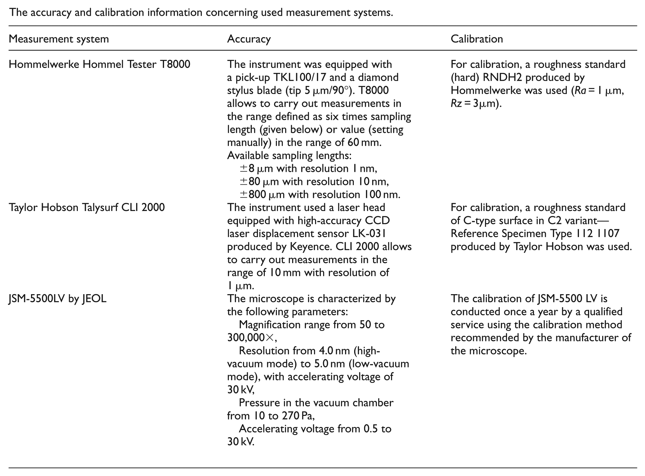
The analysis of the grinding tests and identification of the wear marks on the GWAS were made on the basis of measurements and observations carried out using many modern measurement systems (Figure 4). The accuracy and calibration information concerning the used measurement systems is given in Appendix 2.
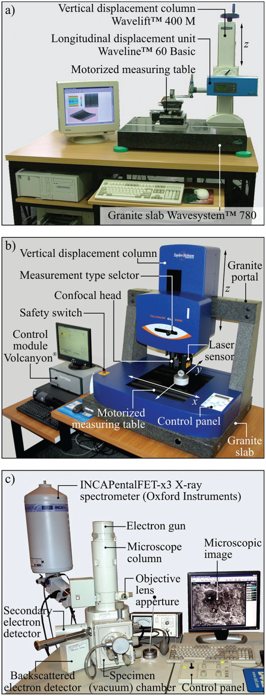
Measuring positions used in investigations: (a) measuring position for roughness stylus profile and microtopographical measurements of workpiece surface with profilometer Hommel Tester T8000 by Hommelwerke GmbH, (b) measuring position for non-contact measurement of the grinding wheel active surface microtopographies with multi-head measuring system Talysurf CLI 2000 by Taylor Hobson Ltd, and (c) scanning electron microscope JSM-5500LV by JEOL Ltd for assessment of the GWAS condition after plunge grinding.
The machined surface roughness parameters were determined on the basis of microtopographies measured by the stylus profilometer Hommel Tester T8000 by Hommelwerke GmbH (Germany) (see Figure 4(a)). Measurements of the GWAS microtopography were made using the multi-head measuring system Talysurf CLI 2000 by Taylor Hobson Ltd (UK), which carries out measurements with the laser triangulation method (Figure 4(b)). GWAS microscopic images were registered on the scanning electron microscope (SEM) JSM-5500LV by JEOL Ltd (Japan) (see Figure 4(c)). The correct identification of details observed on the SEM images was confirmed using an energy-dispersive X-ray spectroscopy (EDS) module INCAPentaFET-x3 from Oxford Instruments (UK).
Results and discussion
The test results obtained were presented separately for each of the three machined materials (sections “Inconel alloy 600”, “Incoloy alloy 800HT,” and “100Cr6 steel”), and then they were compared in section “Summary of grinding results.”
Inconel alloy 600
Figure 5(a)–(c) shows the comparison of the results of the analysis of the active surface of the non-impregnated grinding wheel and the grinding wheel impregnated with sulfur, after grinding of Inconel alloy 600. In Figure 5(d)–(f), the microtopographies of three zones of the Inconel alloy 600 surface after grinding using RGW (Figure 5(d)) and STGW (Figure 5(e)) can be observed. Additionally, a comparison of selected parameters of the geometric structure of particular zones of the machined surface was included (Figure 5(f)).
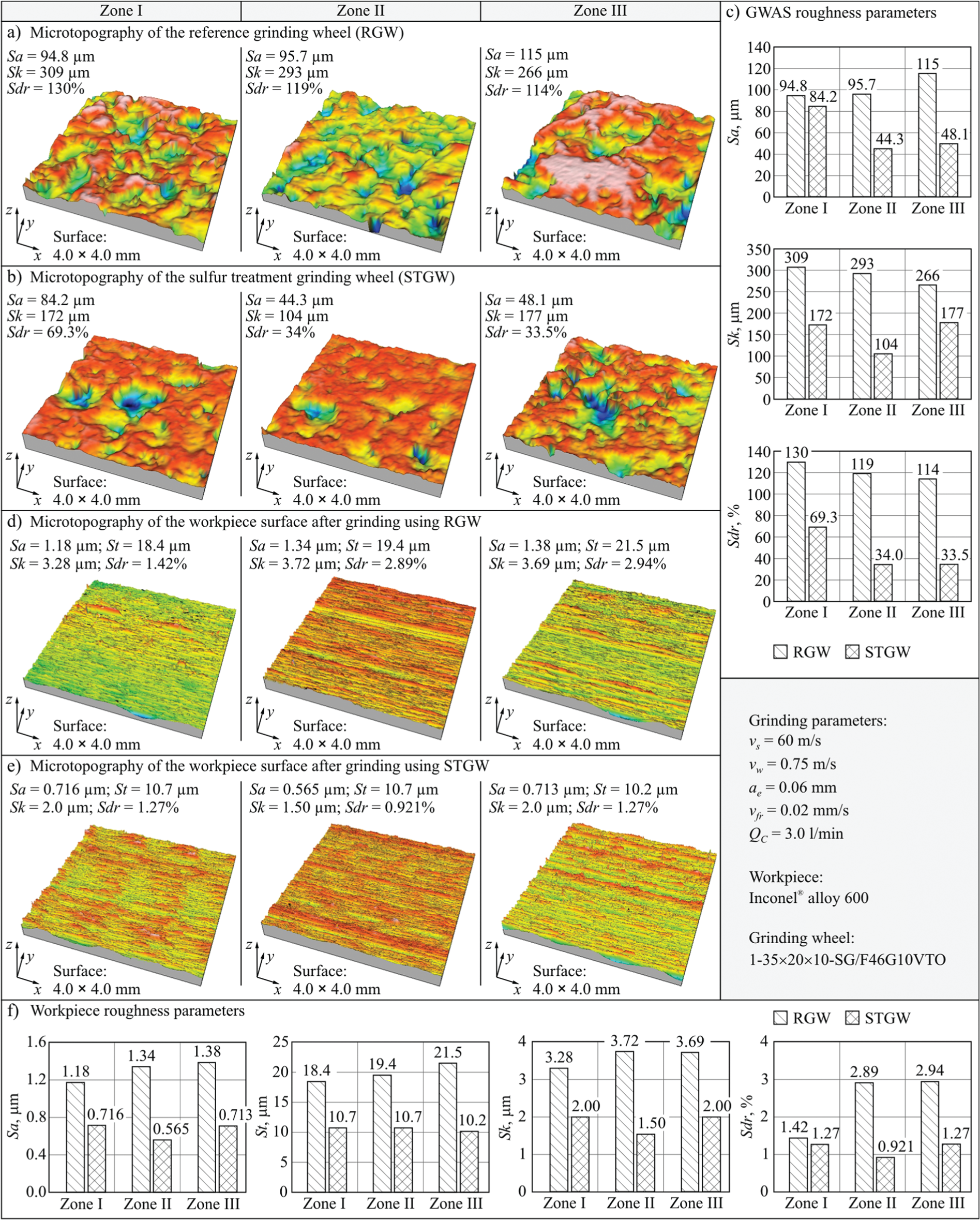
Comparison of microtopography and values of selected roughness parameters of the GWAS (a, b, c) and Inconel® alloy 600 surface (d, e, f) after grinding: (a) microtopography of the RGW, (b) microtopography of the STGW, (c) comparison of selected roughness parameters of the GWAS, (d) microtopography of the workpiece surface after grinding using the RGW, (e) microtopography of the workpiece surface after grinding using the STGW, and (f) comparison of selected roughness parameters of the workpiece surface.
When comparing the condition of the active surface of RGW and STGW after grinding (Figure 5(c)), a significant difference in the height unevenness (Sa), structure (Sdr), and bearing capacity (Sk) was observed. The determined values of the selected GWAS roughness parameters indicate a decrease of approximately 42% in altitude height (abrasive grains), 63% in structural openness, and 48% in the Sk parameter value, which describes the height of the core roughness. These changes were the result of the introduction of sulfur into the free intergranular spaces of the grinding wheel, with no clear influence exerted by the changeable grinding time in particular grinding wheel zones.
The analysis of the values of selected parameters of the geometric structure of particular zones of the Inconel alloy 600 surface after grinding (Figure 5(f)) reveals a significant reduction in the machined surface roughness of the grinding wheel impregnated with sulfur, as compared to the grinding with the non-impregnated grinding wheel. The values of the determined parameters were approximately 50% lower (average change for Zones I–III: Sa ≈ 49%, St ≈ 47%, Sk ≈ 49%, Sdr ≈ 52%) when a grinding wheel impregnated with sulfur was used. This tendency was observed in all three machining zones, but it was more evident in Zone III, in which the grinding lasted longest.
These data suggest that sulfur has a considerable influence on the grinding zone or on the mechanism of chip formation, creation of material pick-ups, ridging, and other phenomena that have decisive impact on the final geometry of the Inconel alloy 600 after grinding.
Incoloy alloy 800HT
Figure 6 presents an overall comparison between the results of analysis of the RGW’s and STGW’s active surface geometric structure (Figure 6(a)–(c)), as well as microtopographies with values of selected parameters of the geometric structure of surfaces of particular zones of the Incoloy alloy 800HT after grinding (Figure 6(d)–(f)).
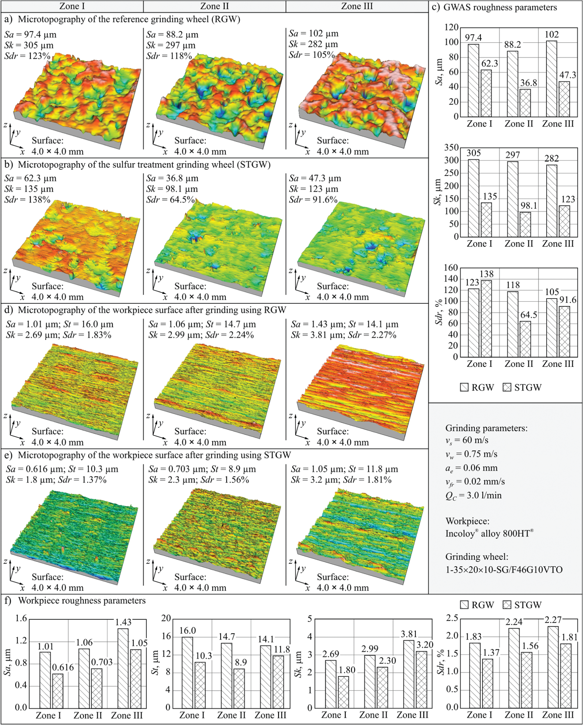
Comparison of microtopography and values of selected roughness parameters of the GWAS (a, b, c) and Incoloy® alloy 800HT® surface (d, e, f) after grinding: (a) microtopography of the RGW, (b) microtopography of the STGW, (c) comparison of selected roughness parameters of the GWAS, (d) microtopography of the workpiece surface after grinding using the RGW, (e) microtopography of the workpiece surface after grinding using the STGW, and (f) comparison of selected roughness parameters of the workpiece surface.
The registered nature of the changes in the parameters describing the grinding wheel microgeometry is analogical with those observed on grinding wheels after grinding Inconel alloy 600. The values of all the parameters analyzed are lower in the case of grinding wheels impregnated with sulfur. Compared to the results obtained after grinding Inconel alloy 600, slightly greater differences in the values of parameters Sa (a 49% decrease on average) and Sk (a 60% decrease on average) were observed. The value of parameter Sdr, which describes the level of GWAS geometric structural development, was in this case only 15% lower on average for STGW (Figure 6(c)).
Similar to the results of grinding Inconel alloy 600, after grinding using a wheel impregnated with sulfur, a considerable reduction in surface roughness was obtained on Incoloy alloy 800HT. For all three zones, the mean arithmetical deviation of surface roughness Sa showed a decrease of 27%–39% in the values determined for the surface shaped with STGW in relation to the results obtained for surfaces after grinding using RGW (Figure 6(f)). The other parameters describing the machined surface roughness in the three working zones changed as follows: St ≈ 16%–39%, Sk ≈ 16%–33%, and Sdr ≈ 20%–30%. These results show that there was an approximately double the decrease in the advantageous influence of STGW application on the quality of the machined surface (average change for Zones I–III: Sa ≈ 32%, St ≈ 28%, Sk ≈ 23%, Sdr ≈ 25%) compared to the results of grinding of Inconel alloy 600 (Figure 5(f)). This may be due to the lower density (Inconel alloy 600: 8.47 mg/m3, Incoloy alloy 800HT: 7.94 mg/m3) and greater resistance to stretching (Inconel alloy 600: 655 MPa, Incoloy alloy 800HT: 786 MPa) of Incoloy alloy 800HT.34–37
It is also worth noting that the smallest differences between the roughness parameters of the surface of Incoloy alloy 800HT after grinding using STGW and RGW were registered in Zone III. This may be indicative of the fact that the grinding wheel operating time and the GWAS wear phenomena may influence the effectiveness of sulfur in the area of contact between the grinding wheel and the machined material.
100Cr6 steel
All the microtopographies of the RGW and STGW active surfaces, as well as the microtopographies of steel 100Cr6 surface after grinding, are illustrated in Figure 7, which also shows charts of the changes in the selected roughness parameters characterizing the GWAS (Figure 7(c)) and the machined surface (Figure 7(f)).
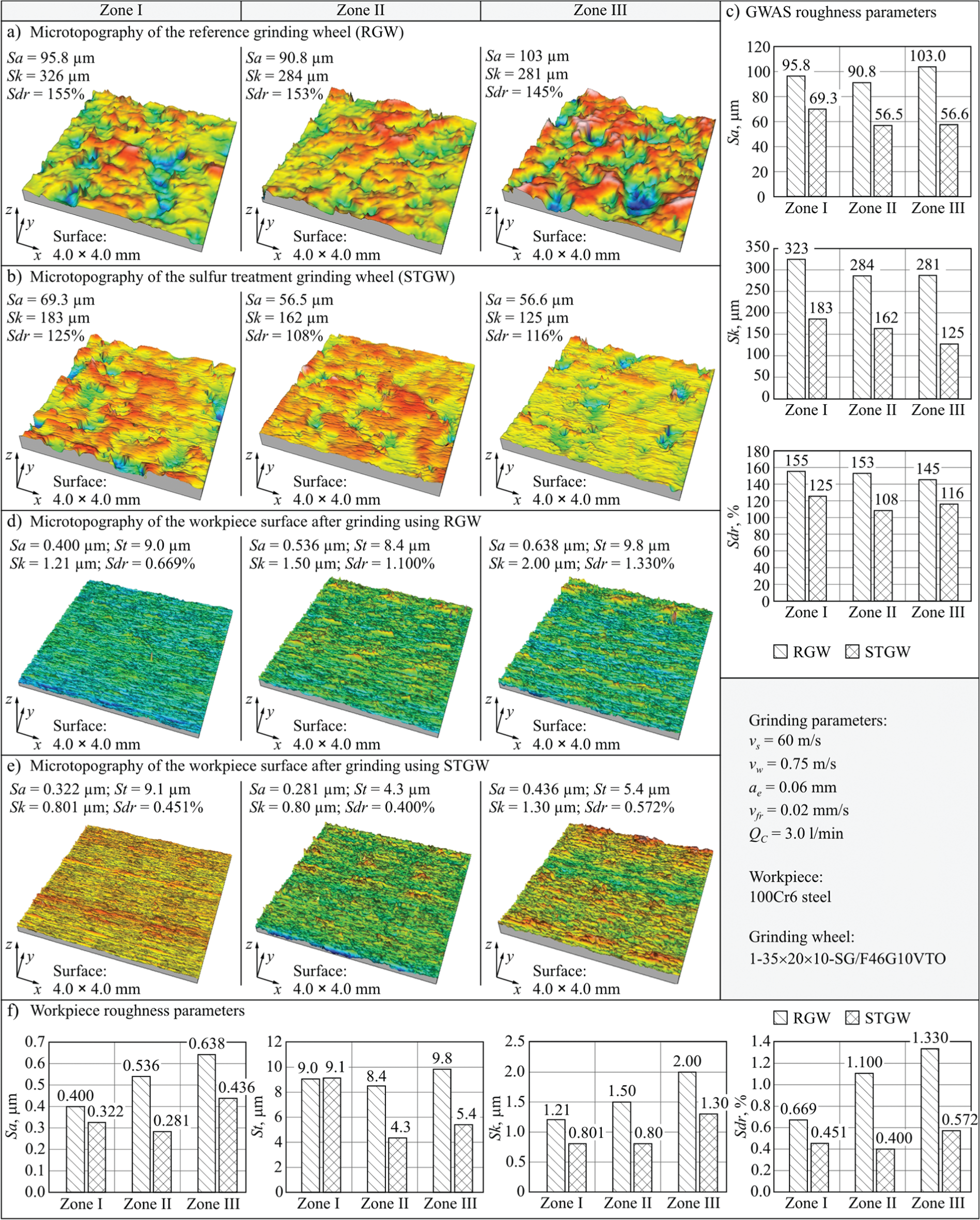
Comparison of microtopography and values of selected roughness parameters of the GWAS (a, b, c) and 100Cr6 steel surface (d, e, f) after grinding: (a) microtopography of the RGW, (b) microtopography of the STGW, (c) comparison of selected roughness parameters of the GWAS, (d) microtopography of the workpiece surface after grinding using the RGW, (e) microtopography of the workpiece surface after grinding using the STGW, and (f) comparison of selected roughness parameters of the workpiece surface.
In the case of the grinding wheel used for grinding steel 100Cr6, the values of parameters describing the stereometric features of STGW surfaces were considerably lower than the ones of RGW surfaces (Figure 7(c)). More specifically, a decrease was observed in the following parameters (after averaging the values from the three examined working zones): 37% for Sa, 47% for Sk, and 23% for Sdr. A clear tendency in the differences between the values of the three levels of the grinding wheel analyzed was not evident in this case.
Steel 100Cr6 was included in the experiments as a referential material to be a point of reference for the results of grinding hard-to-cut materials. The applied steel was initially subjected to a heat treatment that is typical for rolling bearing elements. The ground rings were toughened in oil at 830 °C–840 °C, cooled in water, and then subjected to drawing at a temperature of 160 °C–180 °C over 2 h. As a result, the ground steel assumed a hardness of 62 ± 2 HRC, which places the material in the so-called hard condition category. During the grinding of such materials, short brittle chips are produced that are easily transported in the intergranular spaces outside the grinding zone. Because of this, the smearings/loads of the GWAS are created with far lower intensity than in the case of grinding hard-to-cut materials, in which case long and malleable chips are formed. As a comparison, hardness of Inconel alloy 600 and Incoloy alloy 800HT ranges from 24 to 34 HRC.34–37
The lowest machined surface roughness was obtained during the process of plunge grinding of steel 100Cr6. The values of the workpiece surface roughness, expressed with parameter Sa, ranged from 0.400 to 0.638 µm after grinding with the RGW and from 0.281 to 0.436 µm using STGW (Figure 7(d)–(f)). The maximum measured value of parameter Sa for the surface machined in Zone III was 0.638 µm, while for the surface shaped with the impregnated grinding wheel it was approximately 32% smaller in the same area, that is, about 0.436 µm (Figure 7(f)). This is a truly favorable result, since in the applied experimental method the grinding was stopped at the stage of rough grinding, omitting finish grinding and sparking out.
Summary of grinding results
The values determined for the three analyzed parameters (Sa, Sk, and Sdr) of the geometric structure of the STGW and RGW active surfaces were averaged for subsequent working zones (Zones I, II, and III) and are presented in Figure 8.
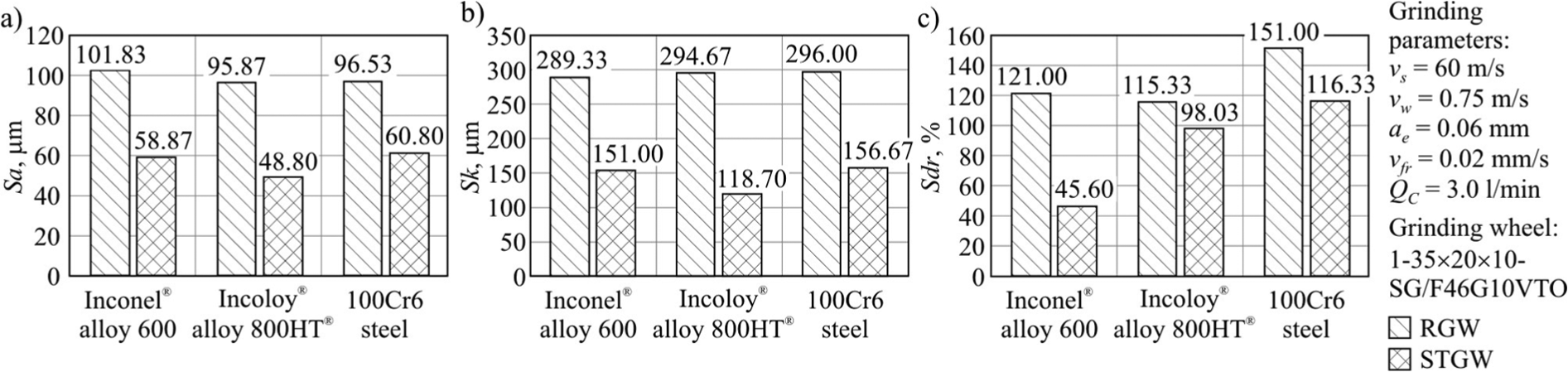
Parameters of the geometrical structure of the grinding wheel active surface with and without sulfur, for all tested workpiece materials (average values of the three working zones of the grinding wheel): (a) arithmetic mean deviation of the surface Sa, (b) developed interfacial area ratio Sdr, and (c) roughness depth of the core Sk.
A comparison of the roughness parameters of the RGW and STGW active surfaces indicates that the introduction of sulfur into the grinding wheel free intergranular spaces during the process developed for impregnation with centrifuging results in considerable limiting of the openness of the examined grinding wheels’ geometric structure. The values of parameters Sa, Sk, and Sdr decreased on average by 43%, 50%, and 34%, respectively (Figure 8(a)–(c)). The obtained measurements were mostly dependent on the conditions of the impregnation process.
The parameters describing the stereometric features of the GWAS were also influenced by the smearing/loading of the surface by the chips of the machined material. In order to identify the form and number of smearings/loads, analysis of the active surfaces of the grinding wheels was performed using an SEM. Figure 9 shows representative SEM images of the active surface of Zone III of RGW and STGW after the process of plunge grinding of the three examined materials.
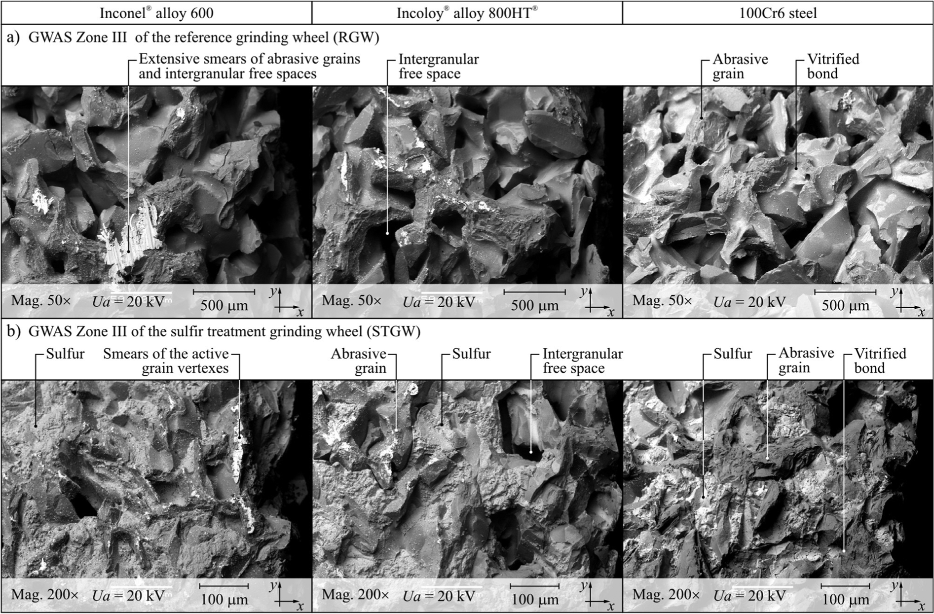
Microscopic SEM images of the GWAS Zone III after plunge grinding of Inconel® alloy 600, Incoloy® alloy 800HT®, and 100Cr6 steel: (a) reference grinding wheel and (b) sulfur treatment grinding wheel.
A comparison of the SEM images of Zone III of the RGW active surface (Figure 9(a)) and the microscopic views of STGW active surface (Figure 9(b)) after grinding indicates comparable limitation in the intensity of creation of vast intergranular smearings/loads. This effect is particularly visible when SEM images of the active surfaces of the RGW and STGW after grinding Inconel alloy 600 are compared.
However, the introduction of sulfur did not prevent the creation of smearing/loading of microareas of the apexes of sintered microcrystalline corundum abrasive grains (Figure 9(b)). In the case of each of the ground materials, such microsmearings were detected on the grinding wheels’ active surfaces; however, there were far less of them on the STGW active surface.
This shows that although sulfur impregnation causes considerable limitation in the volume of intergranular spaces, which was expressed, among other things, in the parameters of the GWAS geometric structure (Figures 5–8), the antiadhesive properties of sulfur resulted in greater smearing/loading of intergranular spaces not created on the STGW active surface. There were also considerably fewer microsmearings of the active abrasive grain apexes (Figure 9).
Figure 10 presents collective charts of values of Sa, St, Sk, and Sdr parameters averaged from the results obtained for particular working zones (Zones I, II, and III) and calculated on the basis of measurements of surface microtopography of those materials machined using RGW and STGW. The prepared charts enabled the conclusion to be drawn, that in the case of grinding nickel superalloys the surface roughness in both these materials was similar and over double that of the easy-to-cut steel 100Cr6, on average (Figure 10).
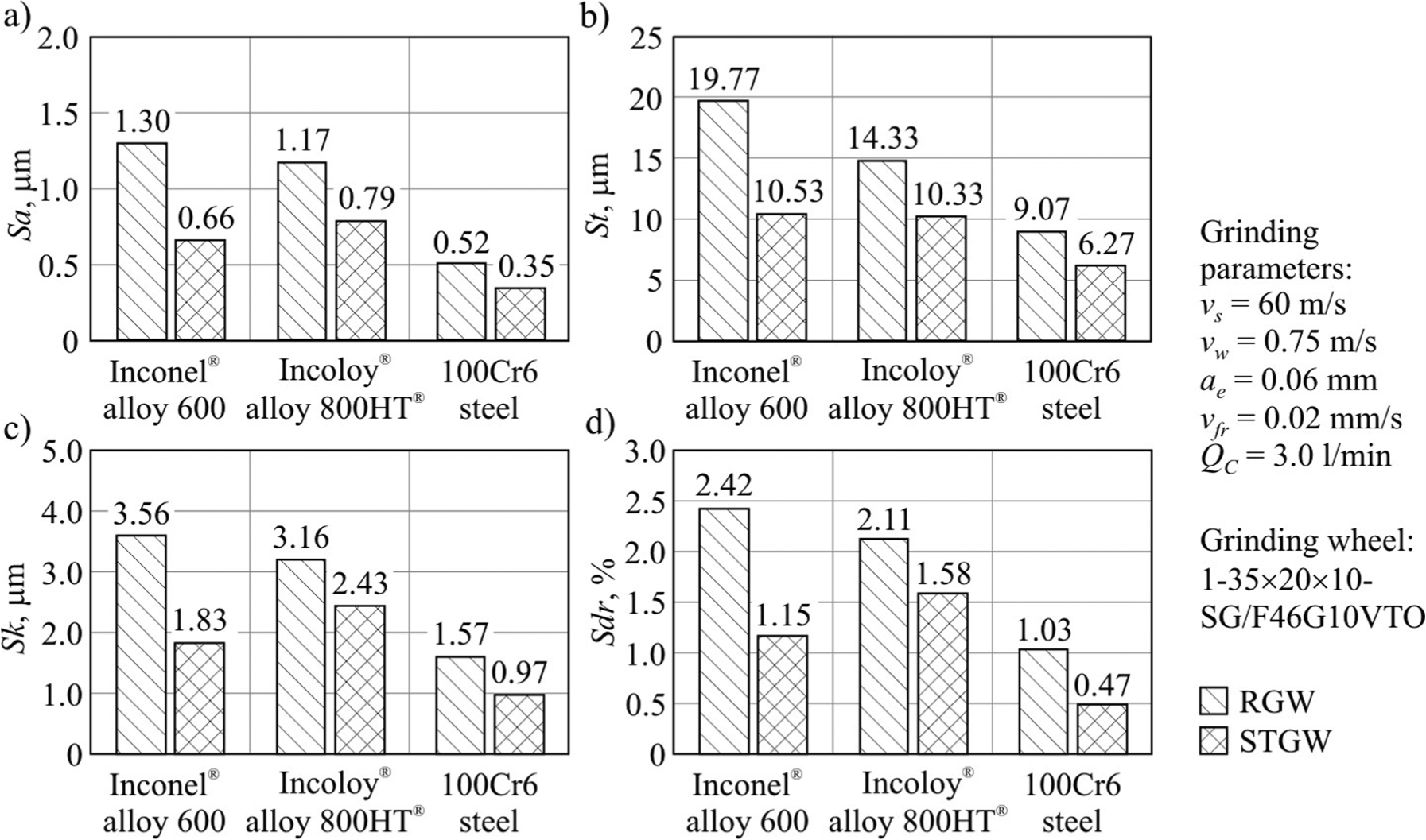
Parameters of the geometrical structure of the workpiece surface machined using grinding wheels with and without sulfur, for all tested workpiece materials (average values of the three working zones): (a) arithmetic mean deviation of the surface Sa, (b) total height of the surface St, (c) roughness depth of the core Sk, and (d) developed interfacial area ratio Sdr.
Among the various machined surface roughness parameters discussed, the most advantageous values were obtained when STGW was applied. Considering the results from all the materials examined, a decrease of 38%, 35%, 36%, and 44% was observed in parameters Sa, St, Sk, and Sdr, respectively (Figures 10(a)–(d)).
It can be concluded that the determined differences were considerable and the presence of sulfur in the grinding zone has a positive influence on the surface roughness after grinding of both hard-to-cut nickel superalloys and steel 100Cr6, and that the beneficial effect of impregnation mainly results from the antiadhesion properties of sulfur. The chemical effects of this modification are very hard to establish in an unequivocally way. In the Ni-based superalloys examined (Inconel alloy 600 and Incoloy alloy 800HT), chromium is an additive in a proportion of 15.5% and 21% and it increases the corrosion resistance. The alloy surface is passivated by oxygen in the air, which forms a thin and very dense layer of oxide that effectively protects the surface. The presence of chromium increases the melting point of nickel alloys by about 200 °C. The grinding conditions are unstable and aggressive, and addition of sulfur (which was only 2.62 g in the total volume of the grinding wheel) has no significant impact on them. At high temperatures, sulfur could react with various elements present in the alloy (especially nickel, chromium, and iron) and lead to the production of non-water-soluble sulfides. However, even in such unfavorable conditions, creation of nickel (II) sulfide, as well as chromium (III) sulfide, in water (grinding fluid) conditions is practically impossible since nickel creates nonstoichiometric forms of nickel sulfide in excess of sulfur. Considering the very short time of contact between the grinding wheel and the workpiece, the amount of sulfide that could be created is only a few parts per billion.
On the contrary to Inconel alloy 600 and Incoloy alloy 800HT, 100Cr6 steel does not contain nickel or chromium, but only iron (carbon is a low reactive). Because iron does not form passive layers, the probability of it reacting with sulfur is higher.
The different results obtained with the steel 100Cr6 and nickel superalloys are mainly due to the diverse characteristics of these materials. Besides the already mentioned difference in hardness, hard-to-cut materials (Inconel alloy 600 and Incoloy alloy 800HT) differ significantly in their chemical composition (Table 3), which determines the mechanical properties and grindability of the alloys. As mentioned in section “Characteristics of tested hard-to-cut materials,” the grindability of nickel superalloys is significantly influenced by high ductility, low thermal conductivity, and susceptibility to hardening during machining. High ductility causes the production of ductile chips of considerable length, whose dimensions are much larger than generated during the grinding of steels. These features have caused described differences in the recorded results of the experiments.
Conclusion
In this article, the detailed effect of sulfur impregnation on the plunge grinding of two nickel superalloys (Inconel alloy 600 and 800HT) compared to easy-to-cut material (steel 100Cr6) is shown for the first time. A new method of adding sulfur into the GWAS (gravitational introduction of sulfur into the ceramic grinding wheel volume, followed by centrifugation) is described, which allows an effective and relatively straight-forward modification of the grinding wheel cutting ability. The most important conclusions resulting from the experimental tests conducted are as follows:
Impregnation with sulfur considerably limits the intensity of GWAS smearing/loading with chips of the machined material.
The advantageous effect of limiting the intensity of creation of GWAS smearing/loading is particularly concerned with reducing the creation of larger smearing/loading of intergranular spaces in a technologically unfavorable manner.
The presence of sulfur in the grinding wheel volume has only limited influence on the intensity with which smearing/loading of the microareas of the abrasive grain vertexes occurs.
The positive influence of impregnating grinding wheels with sulfur, particularly on the obtained roughness of workpieces made from Inconel alloy 600, Incoloy alloy 800HT, and the referential material—steel 100Cr6, was demonstrated; in the tests, differences in the value of parameter Sa, ranging between 32% and 49% for the benefit of surfaces ground with grinding wheels impregnated with sulfur, were obtained.
The time for evaluating grinding test results, in particular the assessment of the GWAS condition, is relatively long and can be shortened with the use of more efficient diagnostic methods like machine vision 38 and systems for the detection of in-process changes of the grinding wheel surface topography. 39
Future research should include maintenance tests on the typical kinematic variants of peripheral internal cylindrical grinding of surfaces made from hard-to-cut materials.
Footnotes
Appendix 1
Appendix 2
The accuracy and calibration information concerning used measurement systems.
| Measurement system | Accuracy | Calibration |
|---|---|---|
| Hommelwerke Hommel Tester T8000 | The instrument was equipped with a pick-up TKL100/17 and a diamond stylus blade (tip 5 µm/90°). T8000 allows to carry out measurements in the range defined as six times sampling length (given below) or value (setting manually) in the range of 60 mm. Available sampling lengths: | For calibration, a roughness standard (hard) RNDH2 produced by Hommelwerke was used (Ra = 1 µm, Rz = 3µm). |
| ±8 µm with resolution 1 nm, | ||
| ±80 µm with resolution 10 nm, | ||
| ±800 µm with resolution 100 nm. | ||
| Taylor Hobson Talysurf CLI 2000 | The instrument used a laser head equipped with high-accuracy CCD laser displacement sensor LK-031 produced by Keyence. CLI 2000 allows to carry out measurements in the range of 10 mm with resolution of 1 µm. | For calibration, a roughness standard of C-type surface in C2 variant—Reference Specimen Type 112 1107 produced by Taylor Hobson was used. |
| JSM-5500LV by JEOL | The microscope is characterized by the following parameters: |
The calibration of JSM-5500 LV is conducted once a year by a qualified service using the calibration method recommended by the manufacturer of the microscope. |
Acknowledgements
The authors would like to thank the employees of Koszalin University of Technology for their help and support in selected steps of the experimental investigations: Mrs Daniela Herman, DSc, PhD, and Mr Tomasz Okupski, MSc, BSc, from the Division of Fundamentals of Materials Science and Technical Ceramics in the Institute of Technology and Education, for preparing the grinding wheels for tests; Mr Andrzej Nowicki from Laboratory Team I for his help during experimental investigations of the grinding process; Mr Krzysztof Maciejewski from the Laboratory of Metrology and Measurement Systems for the stylus measurements of surface microtopography of the workpieces; Mr Ryszard Gritzman from the Central Laboratory of the Institute of Technology and Education for acquisition of SEM micrographs, as well as Mr Robert Tomkowski, MSc, BSc, from the Laboratory of Micro- and Nanoengineering for the optical measurement of the GWAS topographies.
Declaration of conflicting interests
The authors declare that there is no conflict of interest.
Funding
This research received no specific grant from any funding agency in the public, commercial, or not-for-profit sectors.