
Abstract
Laser micro-machining is a promising manufacturing solution for fabricating complex micro-engineering products in wide range of materials that incorporate different multi-scale functional features. Optical beam deflector systems are key components in laser micro-machining systems, and they are one of the main factors determining the processing speed and hence machining throughput. However, their performance is speed dependent and the negative dynamics effects have a direct impact on the laser micro-machining accuracy, repeatability and reproducibility. This article presents a generic software solution for minimising these negative dynamics effects, thus improving significantly the laser machining performance across the full range of available processing speeds. In particular, these improvements are achieved by introducing machine-specific compensations in machining vectors to counteract beam deflectors’ inertia regardless of their directions, length and set process speed. An empirical model was developed to obtain data about the actual dynamic response of the beam deflection system across the full range of available processing speeds, and then based on these data, the proposed generic software was implemented into a stand-alone ‘adaptive’ postprocessor. The generation of machine executable part programs is automated, and it is only necessary for the user to enter the selected scanning speeds and beam diameters. Experimental validation was conducted to demonstrate the capability of the proposed software tool. The results demonstrate that substantial improvements can be obtained in machining quality by maintaining a constant pulse distance throughout the machining operations, while the dimensional accuracy is maintained across the available processing speeds without sacrificing the machining efficiency.
Keywords
Introduction
The demand for function integration and reliability of miniaturised devices has been increasing continuously over the recent years across a large number of application areas such as micro-electromechanical systems, micro-sensor systems and microelectronics.1,2 Research and developments in material science and micro-machining processes (MMPs) are constantly advancing manufacturing capabilities in concerted actions to address these industrial requirements. In particular, manufacturing platforms are designed and implemented for production of components that incorporate different scale functional features down to submicron sizes and functionalised surfaces, while cost efficiency, products’ life cycle characteristics and environmental impact are major considerations in the process design and implementation.3,4 Since the performance of miniaturised products is highly dependent on accuracy, repeatability and reproducibility (ARR) of manufacturing processes utilised for their production, significant research and development efforts are dedicated to advance their capabilities.5,6 However, the widely utilised micro-manufacturing platforms based on lithography processes have some critical limitations in addressing technical requirements of some current and new emerging products, for example, in regard to the materials, capabilities to produce three-dimensional (3D) functional features and their sizes ranging from meso down to nano scales, which makes their fabrication capabilities highly subjective to specific products and also vulnerable to design changes even within their respective target application areas.7,8
At the same time, laser micro-machining (LMM) is a very attractive solution for the fabrication of wide range of products and has some very appealing advantages over other MMPs. 9 Especially, some critical advantages of LMM include non-contact machining, ability to process wide range of materials and complex free-form (3D) surfaces that incorporate functional features with wide range of sizes and capabilities for in situ selective surface characteristic customisation.1–3,5,9
In LMM, the critical demands for ARR are addressed through the integration of a wide range of laser sources in highly controllable direct-writing micro-machining platforms to realise the beam–workpiece relative movements. There are three main machine configurations in designing and implementing LMM platforms: (a) moving workpiece and stationary beam; (b) stationary workpiece and moving beam and (c) combination of both. In Configuration A, the workpiece is mounted on precise linear stages that move the workpiece and determine the machining envelop under a stationary focused laser beam as shown in Figure 1. Complex beam paths can be executed by controlling the stages’ movement. This LMM configuration is widely used in many different manufacturing systems. Therefore, it is not surprising that linear stages as a key component technology in their realisation were widely studied and had attracted a significant research and development interest both from industry and research groups.
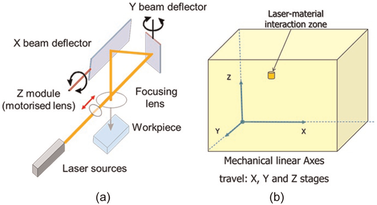
Configuration A LMM: (a) beam delivery system and (b) beam processing envelop.
The stages’ performance both in regard to their ARR and dynamics has undergone constant improvements in the last two decades to deliver repeatable ultra-precise positioning.10,11 For example, they can accommodate movement increments of tens of nanometers, thus realising a very reliable machining in terms of ARR. Furthermore, linear stages’ drivers provide advanced solutions for integrating laser sources in Configuration A LMM systems, in particular for achieving a precise synchronisation of laser pulse firing events with the stages’ movements across the whole machining envelop. Such solutions for LMM platforms are commercially available and incorporate an advanced control tool for positioned synchronised output (PSO) that by controlling the laser firing events delivers a consistent pulse distance (the spacing between the laser pulses) regardless of the workpiece velocity along the machining paths. 12 Nevertheless, an important shortcoming of mechanical stages is their relatively low machining speed, typically it does not exceed 500 mm/s, in comparison to optical axes realised with scanning galvanometer mirrors’ systems. 11 This relatively low speed is a major limiting factor for integrating the latest generation of high-frequency laser sources in Configuration A LMM systems, and therefore, they are usually implemented for a higher ARR machining in expense of relatively high processing time.
Figure 2 presents schematically a Configuration B LMM where the workpiece is stationary while the beam moves along the machining path. A key component technology in such LMM platforms is a scanning galvanometer mirrors’ system, generally referred to as an optical deflection system that realises the computer numerical control (CNC)-controlled movements of the beam along the machining path. Due to their low mass, optical deflection systems do not have the dynamics limitations of mechanical stages and can easily achieve processing speeds significantly higher. Therefore, Configuration B and C LMM can benefit from the highest addressable laser pulse firing rates of the integrated laser sources. However, the higher dynamic performance of the optical deflection systems in comparison to linear stages is in expense of the relatively lower processing ARR. Furthermore, the working envelop of Configuration B systems is limited by the scan field of the used focusing lens system, which typically does not exceed a 50 mm × 50 mm working area, and therefore, such LMM platforms are mostly utilised for the fabrication of components with relatively small overall dimensions. 13
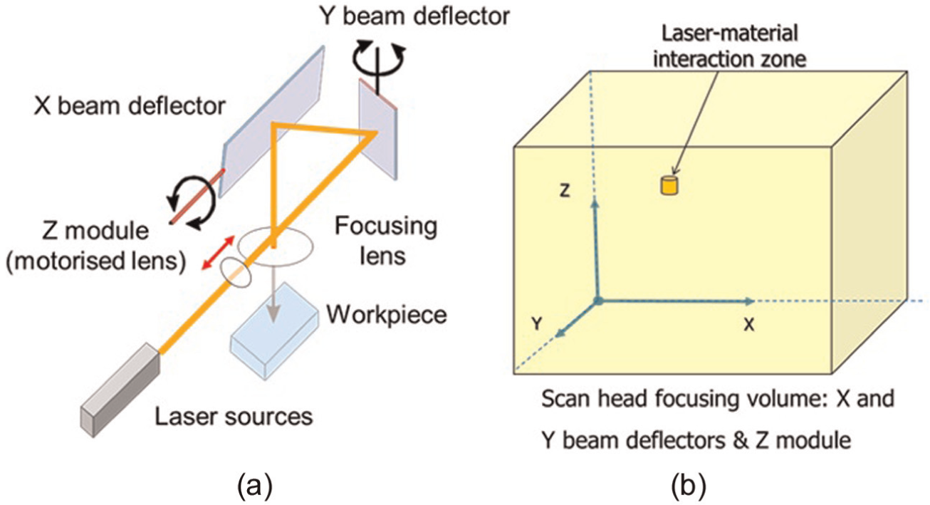
Configuration B LMM: (a) beam delivery system and (b) beam processing envelop.
Finally, LMM is also realised employing Configuration C platform that integrates a CNC-controlled movement of both the workpiece and the laser beam as shown in Figure 3. This LMM configuration benefits from the advantages of both Configuration A and B systems and thus can be employed either for higher ARR processing by utilising the capabilities of the linear stages or for high-speed machining with the optical deflection systems. The development of Configuration C LMM systems that can perform laser processing with simultaneous synchronised movements of both the optical scan head and the linear stages was reported. The main objective in implementing Configuration C LMM systems is the realisation of high-speed machining of workpieces requiring a bigger working envelop realised by the stages. 13 Such a configuration can significantly extend the processing capabilities of LMM systems because it can be used for a higher speed processing of bigger components without the constraints of the used focusing lens system. However, ARR of such LMM platforms is still determined by the optical deflection system because of its ultimate control of the laser beam movements. Therefore, improvements in their ARR performance are essential in order to benefit fully from their high-speed processing capabilities in Configuration B and C LMM systems.
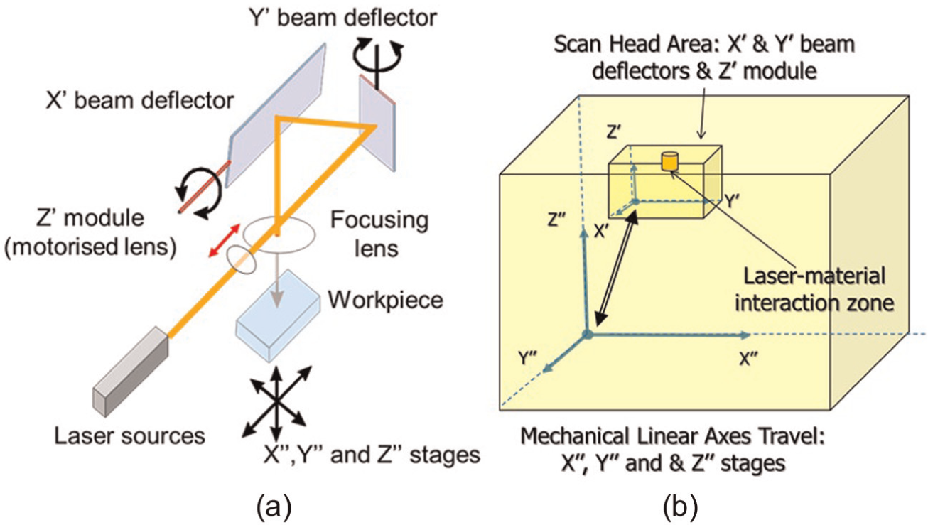
Configuration C LMM: (a) beam delivery system and (b) beam processing envelops of optical and mechanical axes.
This research presents the development of a generic software solution that significantly improves ARR of optical scan heads throughout their full range of available processing speeds, thus improving the overall performance of Configuration B and C LMM platforms.
The next section reviews the state-of-art in optical beam deflection systems with their dynamics effects on the resulting machining accuracy and quality. Then, the proposed software solution is described together with main steps for implementing it. Finally, an experimental verification of the software solution is provided and conclusions are made.
Literature review
Processing capabilities of optical laser beam deflection systems were investigated by a number of research groups and their common conclusion is that they are not sufficiently mature.6,14,15 A general misconception for their capabilities is the presumption that the scanner movement ARR stated in equipment manufacturers’ specifications is an absolute parameter. For example, in an experimental study focused on evaluating ARR of LMM systems, it was concluded that their performance was far away from their stated specifications. 6 Thus, it should be noted that the beam movement accuracy is a relative parameter that depends highly on the operating parameters of the beam deflection system, such as the movement mode and the used scanning speed and machining strategies. Therefore, a deterministic evaluation of the system performance can only be accomplished if the processing framework is pre-defined. Thus, any investigations of LMM systems’ performance should be carried out within a pre-defined processing framework, for example, by employing the vector movement mode and by utilising the full field of view of the used focusing lens.
Optimisations of beam deflection systems to improve machining results were also reported in a number of publications. In particular, the proposed approaches apply ‘a drive signal digital pre-filtering’ technique to improve the dynamics performance of optical beam deflection systems by performing a real-time Fourier analysis of the raw command signals.16–18 However, this technique is not sufficiently effective when it is required micro-engineering components to be produced with high ARR,3,4 and therefore, other MMPs have to be employed together with specially developed software tools to compensate process limitations.19,20 Such software tool for layer-based micro-machining was also reported to improve the resulting surface topography following laser-milling 21 by optimising the slicing procedure and vector orientations in each layer for 3D geometries. However, the proposed software tool does not address ARR issues associated with the negative dynamics effects of the optical beam deflection systems. A commercial beam deflection system that was introduced recently offers a ‘sky-writing’ function for applications requiring a higher accuracy, where each ‘mark’ vector is precisely executed at a constant processing speed over the entire vector length. 22 However, an important shortcoming of this function is that users still need to manually define a set of functional parameters by conducting time-consuming optimisation experiments. Furthermore, the ‘sky-writing’ functionality is available only to customers of this commercially available system, and thus, it cannot be considered a generic solution.
Motivation – main components and working principle
Optical beam deflection systems are closed-loop dynamic systems that consist of reflective mirrors mounted on highly precise galvanometer motors with servo control systems. 23 The galvanometer has two main parts: an actuator that produces a rotary beam deflection in response to electric current and an integral position detector for a closed-loop control. The closed-loop servo system controls the movement of the laser beam by comparing the position detector’s current output signal with the reference input signal, the commanded position, and then drives the actuators to the desired position by introducing the necessary corrective action. 24 Furthermore, the controller also synchronises the laser triggering in accordance to the laser beam movement in order to produce the desired machining patterns. 22
The optical laser beam deflection systems are component technologies in LMM systems that are controlled through discrete numerical control (NC) commands to deliver the required machining movements. Their operation can be customised through a list of user-defined parameters, such as laser delays, scanner delays and processing speeds, which can be set to fulfil specific machining requirements. The optical beam deflection systems support three types of vectors, namely, jump, arc and scan vectors. 22 In essence, jump vectors command rapid beam positioning movements with the laser shatter on, while scan and arc vectors execute machining movements with pre-defined laser processing settings. Throughout the execution of a given machining path, the closed-loop servo system feeds corrective actions into the controller and thus guarantees the precise rotary movements of the beam deflectors. However, even with the implementation of such proportional–integral–derivative (PID) control loop, the corrective actions cannot offset fully the system inaccuracies due to the existence of inertia and damping. 17 Other factors, which limit the performance of optical beam deflection systems, include torsional resonance, heat dissipation, drift, nonlinearities and noise. 18 The dynamics effects due to the system’s inertia increase with the increase in the beam deflectors’ rotary speed that ultimately affect the machining results. The dynamics effects have a direct impact on the resulting machining accuracy and quality and they are discussed in the two sub-sections below.
Machining accuracy
Figure 4(b) gives a simple example of the beam deflection system effects on dimensional accuracy of the laser machining results. It can be clearly seen by referring to Figure 4(a) that the system does not perform the machining movements as intended and there is a speed-dependent discrepancy between the programmed and the actual beam movements. In particular, the machining vectors do not reach the programmed position, and ‘tails’ are formed along the beam path both at the beginning and at the end of each vector. Also, these errors increase with the increase in the processing speed. Figure 5(a) shows an example of a machining vector that was programmed for execution by the beam deflection system while Figure 5(b) depicts the actual response of the mirror galvanometers to the programmed movement command. It can be clearly seen that there is a discrepancy between the programmed and actual machining paths that results from the existence of acceleration and deceleration regions at the start and end of each machining vector, respectively. These machining errors occur because the programmed path and the set scan speed only without the dynamics of the beam deflection system were taken into account when generating the control signal for the galvanometers’ rotary movement. In particular, the errors represent the difference between the programmed movement with a constant scan speed and the actual path without the effects of the galvanometers’ dynamics, especially a shorter travel than intended.
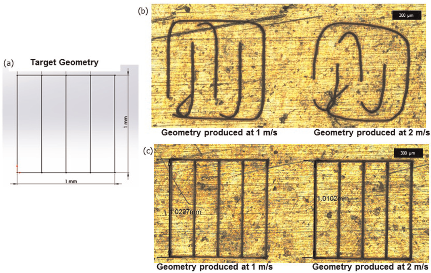
Dynamics effects of an optical beam deflection system on the dimensional accuracy during the laser machining of (a) target geometry (b) with deactivated scanner and laser delays and (c) with activated scanner and laser delays.
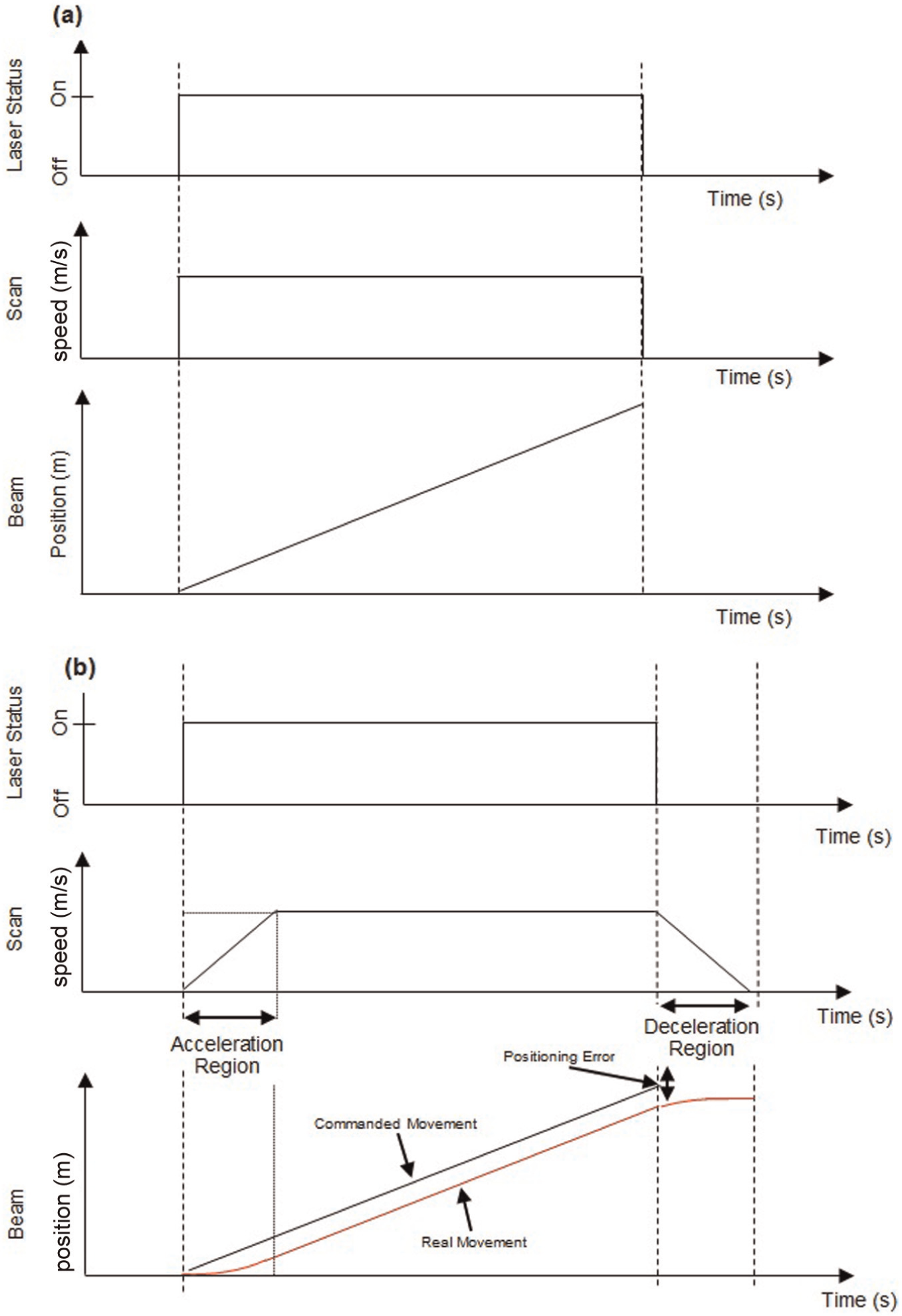
An example of (a) programmed machining vector and (b) executed machining vector.
The state-of-the-art optical laser beam deflection system has the capabilities to compensate the dynamics effects by introducing delays in the galvanometer rotary movements and also in triggering the lasers.17,22 Figure 4(c) exemplifies the improved machining accuracy that can be achieved with the introduction of scanner and laser delays. There are three types of scanner delays, namely, jump, mark and polygon delays, that have to be included after each jump or scan command and effectively give more time to the mirror galvanometers to complete the programmed movements. Additionally, there are two types of laser delays, namely, laser-on and laser-off delays, which adjust the triggering of the laser to the amended laser beam movement with the incorporated time compensations for the galvanometers’ acceleration and deceleration regions. Furthermore, laser delays are also used to compensate the response time of the employed laser source. In particular, the lag between the executed and the programmed movements is compensated with a mark delay as shown in Figure 6, which gives the mirror galvanometers more time to complete a machining command while the laser-on and -off delays are adjusted in accordance to the beam deflectors’ real movement. The introduction of scanner and laser delays can improve significantly the dimensional accuracy of produced components and thus minimises and even eliminates the scanners’ machining errors by providing enough time for the scanners to complete the programmed movements as exemplified in Figure 6. However, it should also be noted that the introduction of scanner and laser delays can be very time-consuming and tedious task because the delays need to be optimised for different processing speeds and also for different machining geometries. 18 Furthermore, the introduction of scanner delays does not eliminate the varying pulse distances at the start and the end of each machining vector (see Figure 6) with its negative side effects (see the section below) and also increases the machining time.
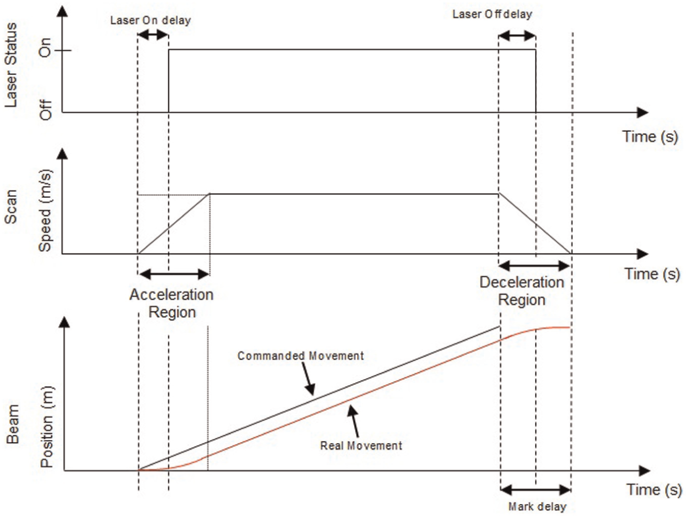
Introduction of scanner and laser delays to improve machining accuracy by eliminating positioning errors of scanner systems.
Machining quality
The scanner dynamics affects also the machining quality, especially the uniform ablation of material across the whole processing area. This is the result of the varying pulse distance, dp = Vs/fp, where Vs and fp are the beam scan speed and pulse frequency, respectively. In particular, since fp is constant across any laser machined area, the changes in Vs in the acceleration and deceleration regions leads to variations in the pulse distance at the beginning and the end of every scan/machining vector. Thus, more laser pulses are irradiated in these regions as shown in Figure 7, which is the reason for not having a uniform material ablation along the beam path.
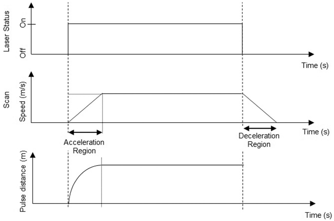
Pulse distance variations with the increase in the scan speed in the acceleration region of a machining vector.
Even though fine tuning of scanner and laser delays could lead to marginal improvements in machining quality, they are not sufficient to achieve optimal machining results because the acceleration and deceleration regions are still present even after the introduction of delays. This is due to limitations in integration architectures of laser sources and scanner systems, especially the limited capabilities of scanner drivers to vary the laser processing parameters ‘on the fly’. Especially, the main components of LMM systems, for example, laser sources, scanner systems and mechanical stages, are controlled independently with limited exchange of control data, and thus, their operations cannot be fully synchronised when executing machining vectors. An evidence of this not fully synchronised control of LMM component technologies is non-uniformed material ablation across the laser-processed areas. Figure 8 depicts the accumulated result of this non-uniform processing after layer-based laser machining of a pocket, in particular after ablating five layers (five scans of machining vectors) on a stainless steel specimen.
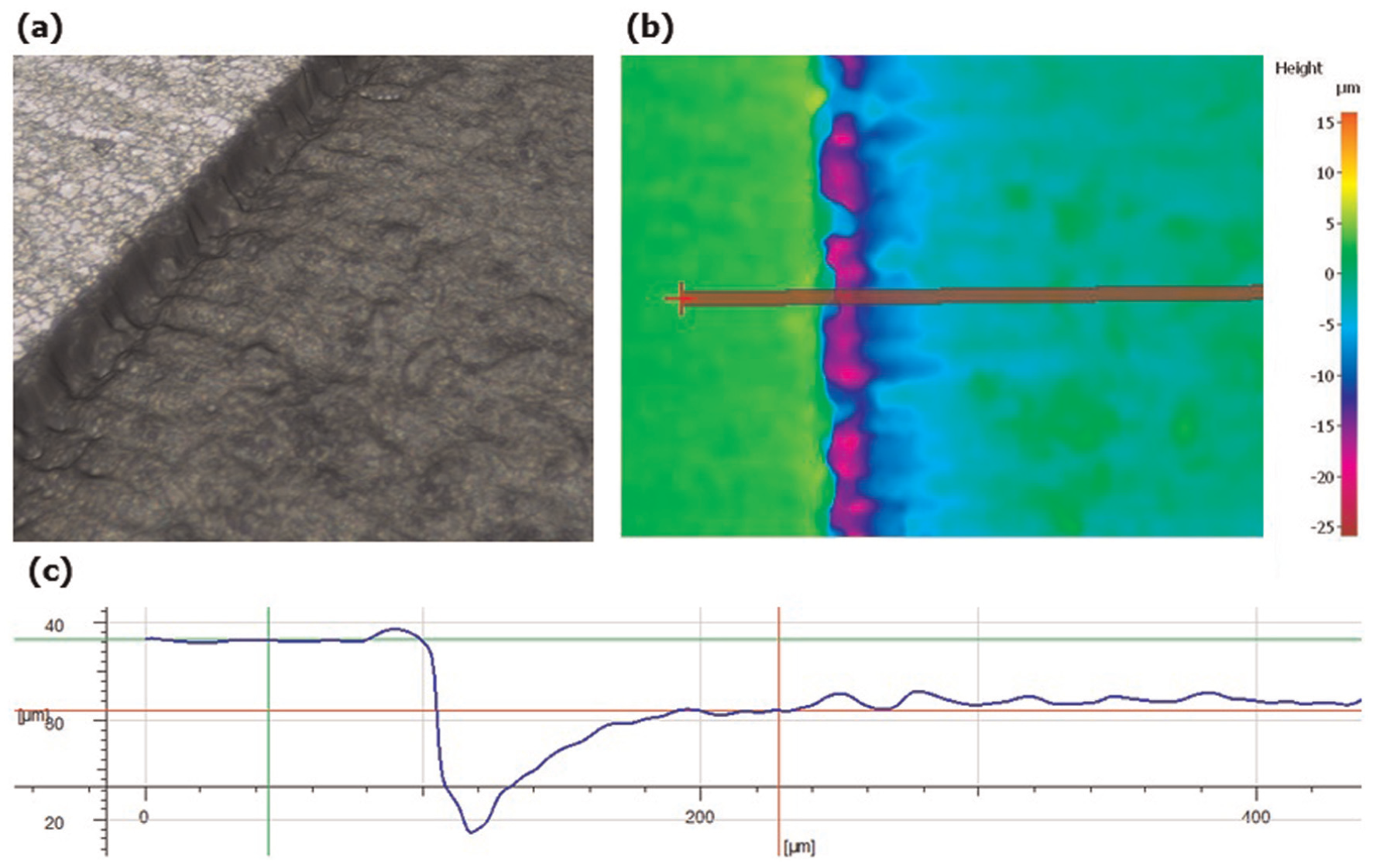
The non-uniform ablation after processing five layers of material: (a) 3D view, (b) contour plot and (c) profile cross section on the ablated region.
Software tool for offsetting the dynamic effects
Taking into account the limitations of the currently available control architectures for integrating laser sources with beam deflection systems, especially in the context of Configuration B and C LMM, a software solution to improve both dimensional accuracy and machining quality is proposed. This is achieved by developing an adaptive computer-aided design (CAD)/computer-aided manufacturing (CAM) postprocessor that minimises the dynamics effects of beam deflection system on the LMM systems’ ARR. This adaptive solution supplements a conventional postprocessor that only translates the beam path created based on the CAD data into an NC part-program for a given LMM system configuration. In particular, this adaptive postprocessor includes the capabilities of the conventional postprocessor for translating the beam movements into machine executable commands plus capabilities to introduce systematic changes, in particular compensations for the beam deflector acceleration and deceleration regions, into the machining vectors. Thus, it becomes an ‘active layer’ between the standard CAD/CAM process and LMM systems. Its functionality includes, apart from translating jump and machining vectors into machine executable commands, the introduction of machine and process settings’ dependent compensations in order to offset the specific dynamics effects of the used beam deflectors.
The proposed adaptive postprocessor minimises and even eliminates the discrepancies between the programmed and actual beam movements in the acceleration and deceleration regions of machining vectors by introducing beam path adjustments while improving the machining quality by maintaining a constant pulse distance during all machining commands. This is achieved by calculating machine-specific compensation values based on the used beam scanning speed that equal the necessary acceleration and deceleration distances to reach the set scanning speed. The system architecture of this adaptive postprocessor is schematically presented in Figure 9. The postprocessor is initiated with the input of a cutter location (CL) data file, which represents the laser beam path generated directly from the part CAD model for a selected laser machining strategy. 21 Such CL data files can be generated by most commercially available CAM software tools, and a detailed description of the CL data generation for layer-based machining is reported by other researchers. Following the input of the CL data, it is necessary to enter laser machining parameters, namely, scan speed and laser beam diameter. Then, the postprocessor introduces systematic changes to the beam path that are compensations for laser delays and laser beam diameter in machining vectors. Finally, the postprocessor outputs an NC file that contains machine executable commands to realise the beam path by taking into account the NC technology language of a given LMM system and also includes a text header with the optimised laser delays.
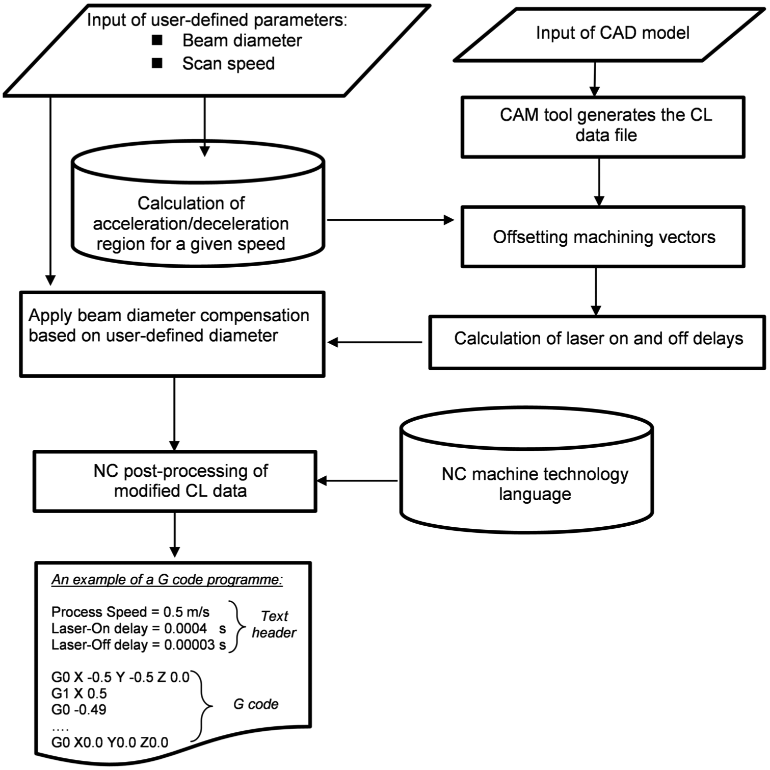
The architecture of the adaptive postprocessor.
The implementation of the proposed adaptive postprocessor, especially its ‘active layer’, includes the following two steps:
Step 1. Offsetting of machining vectors
It is necessary to obtain experimentally information about the dynamics of the beam deflection system used in any given LMM system. Especially, an empirical model has to be created that characterises the actual dynamics response of the beam deflection system when executing machining vectors across the full range of accessible processing speeds. Experimental tests have to be conducted that include the machining of single lines with different processing speeds, thus obtaining information about the acceleration and deceleration regions at different scan speeds. Based on such data, a regression model can be created to determine la≈f (V, β), where V is the scan speed, la is the acceleration region length and β is the regression parameters.
Such empirical models can be used also to predict deceleration region lengths (ld) at different scan speeds by assuming a symmetrical dynamics performance of the beam deflection system at the end of each machining vector. By applying these models, scan speed–dependent compensations to each machining vector can be introduced that in practice represent offsetting values of the vectors’ start and end points with la and ld, respectively.
Step 2. Application of laser delays
Following the offsetting step, the laser-on and -off time events should be adjusted to maintain constant pulse distances when executing laser machining commands and thus have a uniform laser ablation over the processed areas. Thus, it is necessary to find the time that the beam deflection system needs to travel through the acceleration region and thus to calculate the laser-on delay. Since laser-on time events are triggered by the laser source controller, they can be calculated based on the assumption that the beam deflectors travel with a constant speed throughout the full length of a given machining vector. Consequently, the time (ta) required by the beam deflection system to cover an acceleration region at a certain speed can be calculated as follows
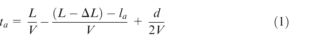
where L is the nominal length of a machining vector, ΔL is the deviation (machining error) between the nominal and the actual lengths of the vector, V is the programmed scan speed and d is the laser beam diameter. Since ΔL is a speed-dependent parameter, experimental tests have to be performed in order to derive their interdependence empirically. Again, based on such experimental data, a regression model can be created, in particular ΔL≈f (V, β).
Thus, to minimise the machining errors and achieve laser processing with a constant pulse distance, it is necessary to apply a laser-on delay (ton) at the start of each machining vector that is equal to ta at the set scan speed for a given beam deflection system. At the same time, laser-off delay (toff) is calculated as follows
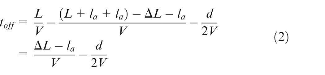
In addition, a compensation for the laser beam diameter is introduced in this step. This is achieved by adding and subtracting a time constant (d/2V) from ton and toff, respectively.
Figure 10 exemplifies how such systematic compensations for the dynamics of the beam delivery system can be used to ‘adapt’ machining vectors to the set scanning speeds and then by applying the necessary laser-on and -off delays to obtain a constant pulse distance when executing machining commands. Thus, it is ensured that the real movements of the laser beam are executed with no discrepancy from the laser beam movement commands. Furthermore, the use of such a postprocessor also eliminates the need to apply laser beam diameter offsets because they are already included into the generated machine executable commands and no further changes into the CAD and/or CAM models are needed in order to achieve positional accuracy and machining quality improvements in Configuration B and C LMM platforms.
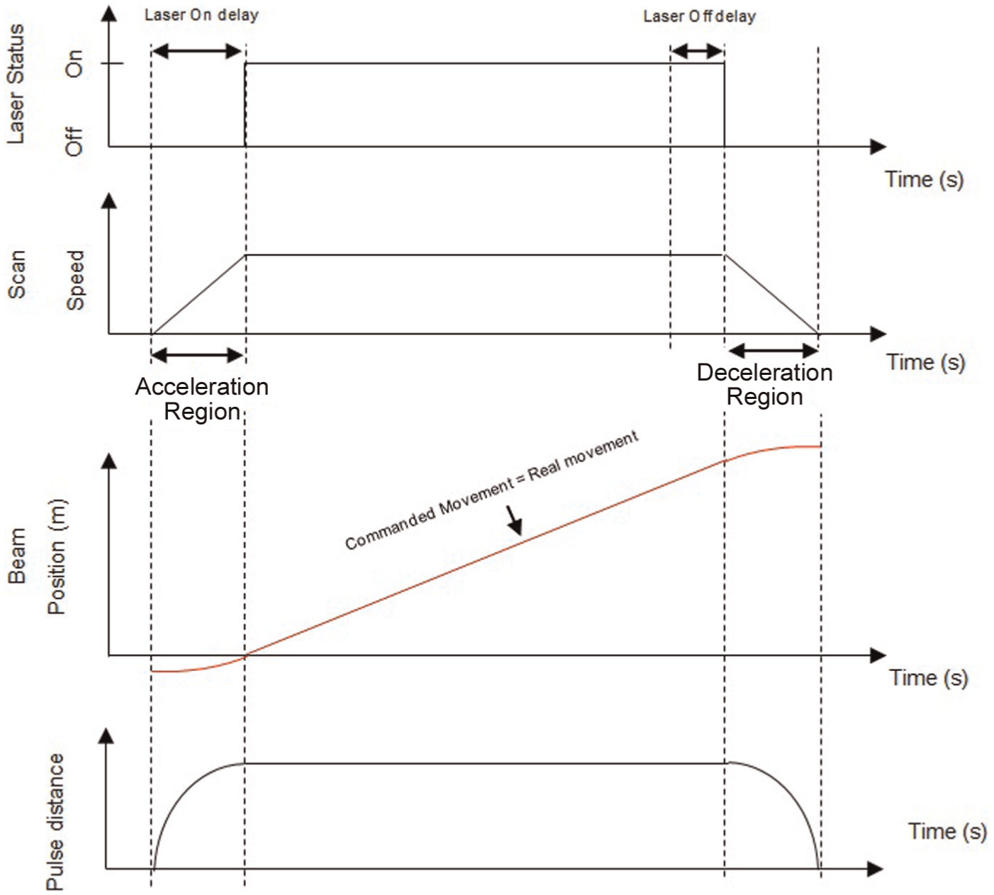
The combined effects of applying the adaptive postprocessor on positional accuracy and machining quality.
The proposed adaptive postprocessor was implemented using a commercially available software tool for creating postprocessors, in particular Delcam PostProcessor, and then integrated into commercial CAD/CAM systems, in particular ArtCam and PowerMill, to validate its performance. Since dynamics behaviour of beam delivery systems is already taken into account by this postprocessor, the generation of beam paths and then machine executable part programs is fully automated. Thus, users can benefit from this software solution regardless of their knowledge and experience with the used specific Configuration B and C LMM systems.
Experimental validation
Experimental setup and acquisition of actual dynamic response of the beam deflection system
Experimental tests were performed on a Configuration B LMM platform that is equipped with a state-of-art beam deflection system. The platform integrates two laser sources – an SPI redENERGY G4 S-type 50 W fibre laser that operates at a central wavelength of 1064 nm and can deliver repetition rates of up to 1 MHz and an Amplitude Systemes Satsuma 5 W ultrafast fibre laser that operates at a central wavelength of 1030 nm and can deliver repetition rates of up to 500 kHz. The laser platform is equipped with a 100-mm telecentric focusing lens, which has an optical machining field of view of 35 mm × 35 mm.
Experimental tests were conducted on the platform to determine the dynamic effects of the beam delivery system integrated in it. As it was explained in section ‘Software tool for offsetting the dynamic effects’, these experiments were necessary to obtain the machine-specific information that is required to implement the proposed software tools. In particular, the experiments included the machining of single lines with different processing speeds to obtain information about the acceleration and deceleration regions at different scan speeds. Figure 11 depicts the interdependences between acceleration region lengths and scan speeds for the used beam deflection system. Based on this result, an empirical model is generated to determine the acceleration region length, in particular

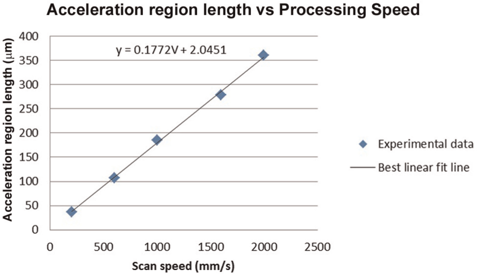
Interdependences between acceleration region lengths and scan speeds.
In addition, further experiments were conducted to determine the machining error (ΔL) dependence on the scan speed on this LMM platform. Again, this is necessary in order to implement the proposed software tool. Especially, Figure 12 shows the interdependence between the machining errors and the set scan speeds for the used LMM platform. Based on these experimental results, the following empirical model is created

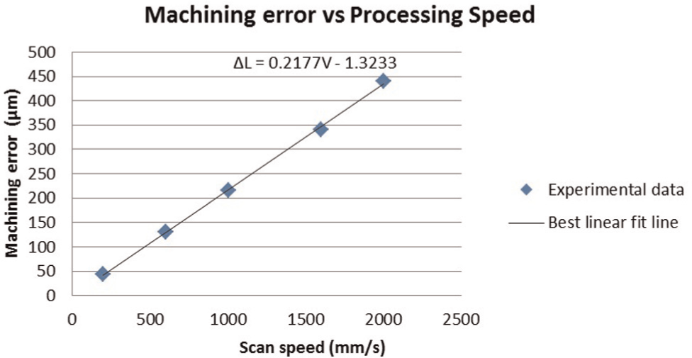
Interdependences between the machining errors and the set scan speed.
The measurements and analyses of experimental results were performed on an optical 3D microscope, namely, Alicona Infinite focus G4. With this system, measurements of both form and surface topography were carried out with maximum lateral and vertical resolutions of 400 and 10 nm, respectively.
Experiments’ design
Lines’ machining
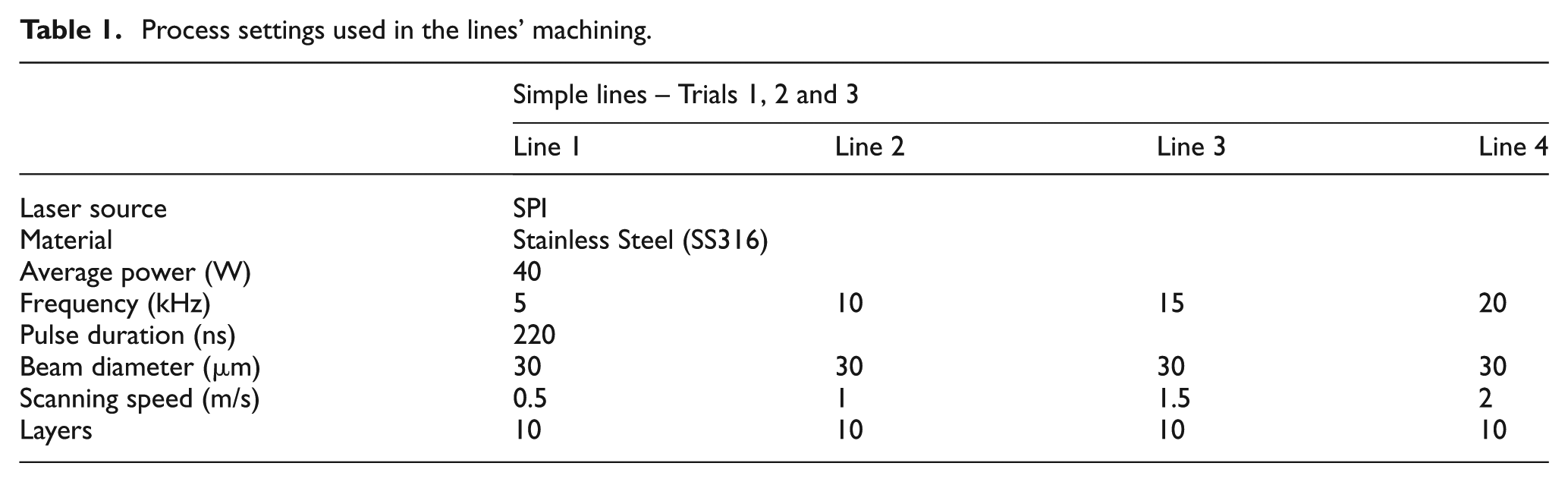
The experimental validation of the proposed software solution for offsetting the dynamics effects of the scan heads included the machining of simple lines on the sample surface to demonstrate clearly the benefits of the proposed tool for improving the ARR capabilities of the optical beam deflection systems. The lengths of the lines were set to 2 mm in order to perform high-resolution measurement of the produced geometries. In addition, lines were produced along x- and y-axes of the optical beam deflection system, thus demonstrating the effectiveness of the proposed software solution regardless of machining vectors’ directions. This simple test structures were produced both before and after applying the proposed software tools in order to assess their effectiveness in improving the machining results. Especially, to validate both the proposed adaptive postprocessor under different dynamics conditions, four processing speeds were investigated. Furthermore, each line was scanned 10 times, thus drawing conclusions about the effects of the proposed tool on ARR capabilities of the used LMM platform. The machining of the lines was carried out on Stainless Steel (SS316) specimens by employing the SPI laser source. The laser machining parameters used are provided in Table 1. The laser frequency was varied with the increase in the scan speed in order to obtain single pulse craters. The appropriate laser delays were calculated for the respective process speed by using equations (1) and (2). Using these process settings, the following three machining trials were conducted:
Trial 1: machining of lines without applying the software tool.
Trial 2: machining of lines without applying the postprocessor, but with optimised scanner and laser delays.
Trial 3: machining of lines after applying the stand-alone adaptive postprocessor both along the x- and y-axes of the beam deflector system.
Process settings used in the lines’ machining.
Machining of passive waveguide filters
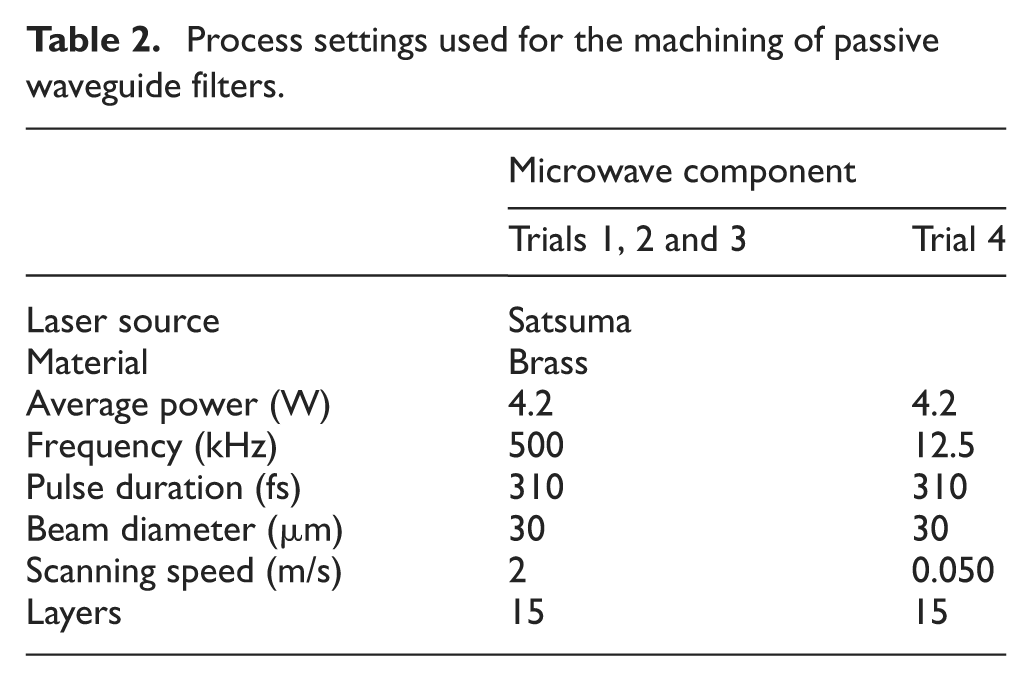
The experimental validation of the adaptive postprocessor is also performed on an intricate 3D geometry with a micro-engineering application. The component is a passive waveguide filter, 8 which was selected due to its complex geometry, which includes micro- and meso-scale functional features. Thus, the effectiveness of the proposed software tools was evaluated both across the full field of view of the used focusing lens system and for machining micro-scale structures. Figure 13 shows the CAD model of the waveguide filter with its nominal dimensions. The machining of the waveguide structure was carried out on a brass specimen by employing the Satsuma laser source. The machining strategy employed in the trials generated machining vectors that are normal across the waveguide length, and layer-based processing was used to produce the 3D structures. The used laser machining parameters are provided in Table 2. The laser processing settings were optimised to achieve the functional requirements for this passive waveguide filter, in particular a surface roughness (Ra) better than 300 nm. The laser delays are again calculated by applying equations (1) and (2). The impact of the proposed adaptive postprocessor on laser machining time and thus the machining effectiveness were also assessed. It is important to note that the machining without applying the adaptive postprocessor required a substantial lowering of the scan speed in order to obtain comparable machining results from both the tests. Thus, a total number of four machining trials were conducted, in particular the following:
Trial 1: machining of the microwave filter without applying the postprocessor at a high scan speed.
Trial 2: it is the same as Trial 1, but with optimised beam deflection system and laser delays.
Trial 3: machining after applying the adaptive postprocessor and by using the same scan speed as in Trial 1.
Trial 4: machining without applying the postprocessor but with the optimised (reduced) scan speed (calculated using equation (4)) in order to obtain similar machining results to those in Trial 3.
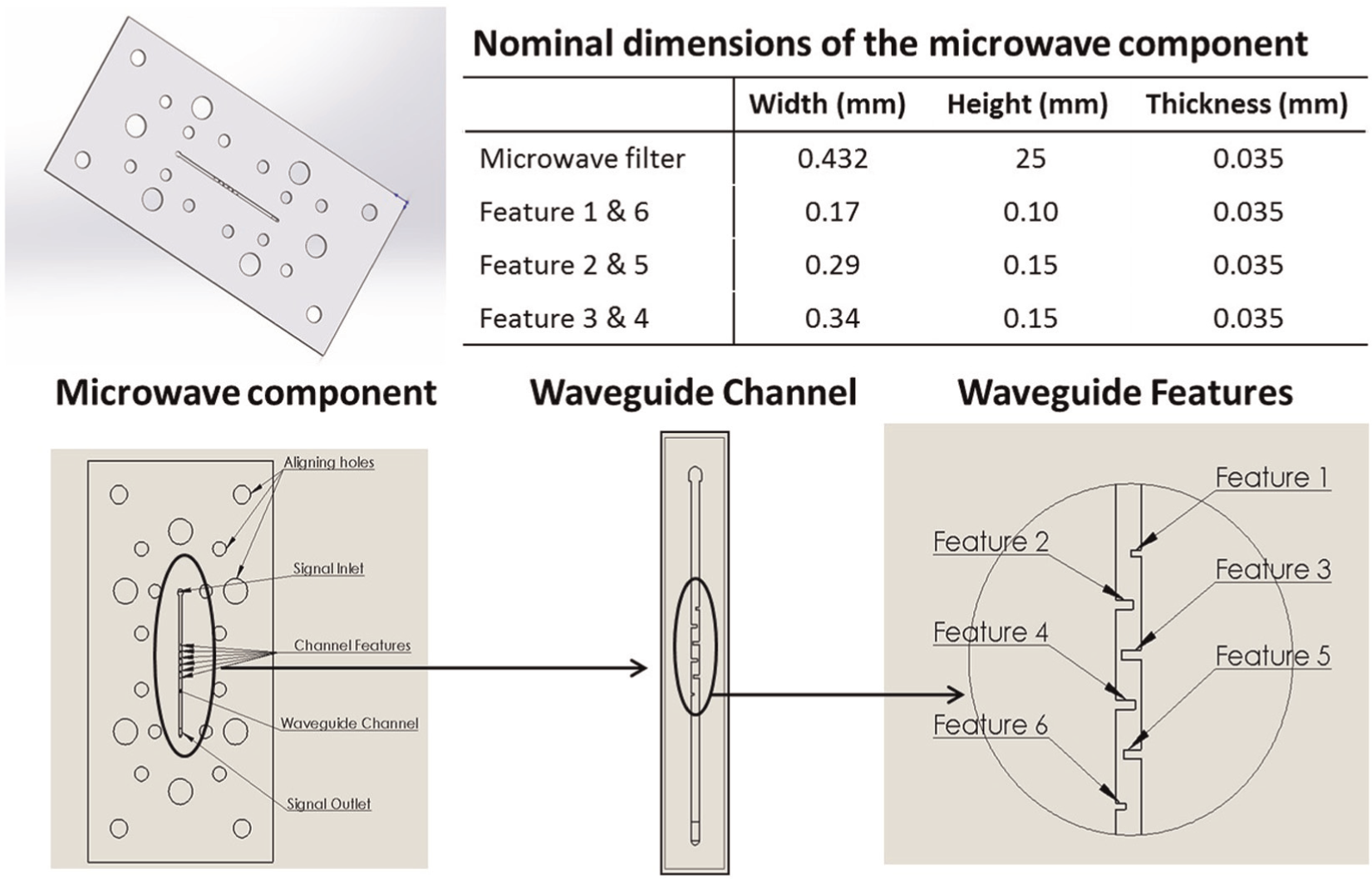
The design of the microwave filter together with its important nominal dimensions.
Process settings used for the machining of passive waveguide filters.
Results and discussion
Single pulse craters’ lines
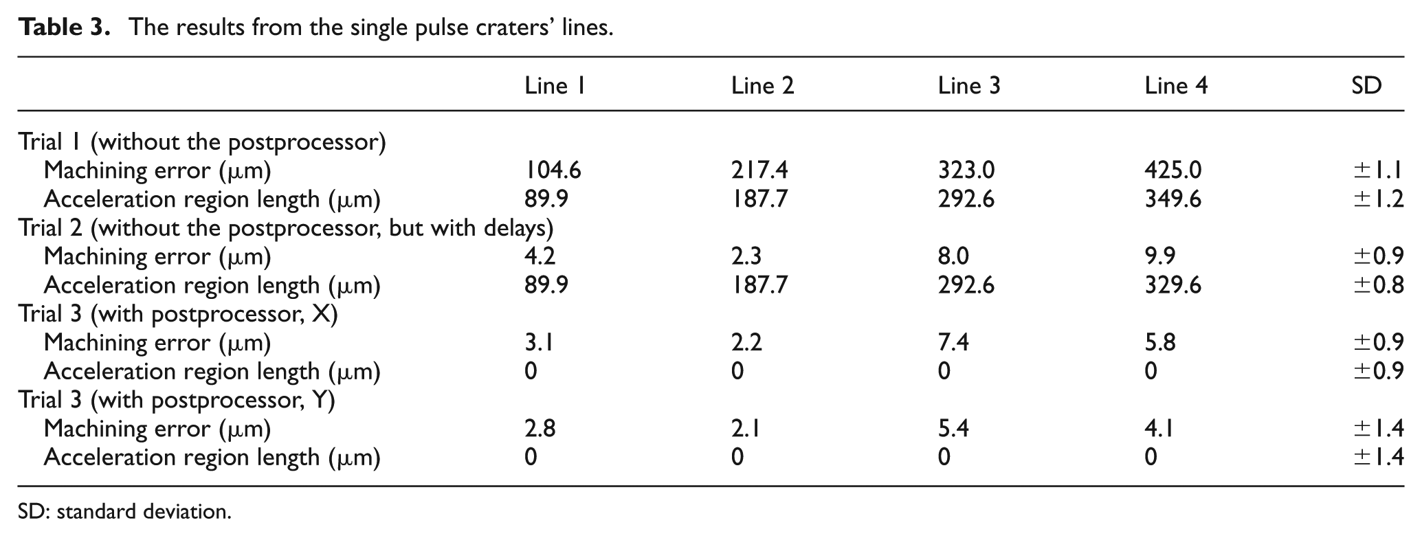
The results from the machining of single craters’ lines to validate the proposed adaptive postprocessor are shown in Figure 14, while Table 2 provides machining errors and acceleration region lengths at the applied scan speeds in the three trials. The measurement uncertainty, in particular the standard deviations (SDs), was calculated by conducting each measurement 10 times and it is provided in Table 2. 6 Figure 14(a) shows the results from the machining of the horizontal lines without applying the proposed postprocessor. It can be seen that each of the lines is shorter than the programmed length of 2 mm and the machining accuracy decreases with the increase in the scan speed. For example, at 0.5 m/s, the machining error is 107.3 μm, while at 2 m/s it is 431.9 μm. Furthermore, the machining quality at the beginning of the lines is much worse in comparison to their middle sections, which is due to the increasing scan speed and changing pulse distance in the acceleration regions as shown in Figure 15. In addition, Figure 15 shows that the acceleration region length increases with the increase in process speed. Once the beam deflector system reaches its set scan speed, the pulse distance becomes constant, and as a consequence, the distance between the single pulse crater becomes uniform as this can be clearly seen in Figure 14(a). Figure 14(b) shows the results of the machined horizontal lines without applying the proposed postprocessor, but with optimised scanner and laser delays. Even though the introduction of the appropriate scanner and laser delays can significantly improve the dimensional accuracy of the laser-processed simple lines, in particular the deviation was reduced to ±10 μm, the machining quality of the lines is not acceptable, because the pulse distance is not kept constant along the laser machining path. In addition, the laser processing of short vectors with lengths comparable to the sum of acceleration and deceleration lengths can be difficult to realise without reducing substantially the scanning speed and thus sacrificing the machining efficiency. Figure 14(c) shows the results of the machined horizontal lines after applying the proposed adaptive postprocessor. The machining errors were reduced, and the process ARR was improved dramatically to be able to produce lines with deviations less than ±10 μm from their nominal dimensions regardless of the set scan speed. Furthermore, the quality of produced lines in Trial 3 is also improved because the pulse distance is maintained constant throughout the whole length of the lines, which results in uniform distances between the single pulse craters. This allows laser processing of different size features regardless of the set scan speed, even if the machining vectors are much smaller than the respective acceleration and deceleration lengths. Table 3 summarises the results from the machining of X and Y lines with the proposed adaptive postprocessor and they are comparable along both the axes. Thus, this demonstrates that the performance of the proposed software tool does not depend on the direction of the machining vectors. Also, Trial 3 demonstrates that machining results with pseudo-repeatability of less than 1.5 μm at different scan speeds can be achieved by maintaining the pulse distance constant whenexecuting the machining vectors. In addition, based on the results from Trial 3, it can be stated that a reproducibility of less than 7 μm was achieved regardless of the set scan speed.
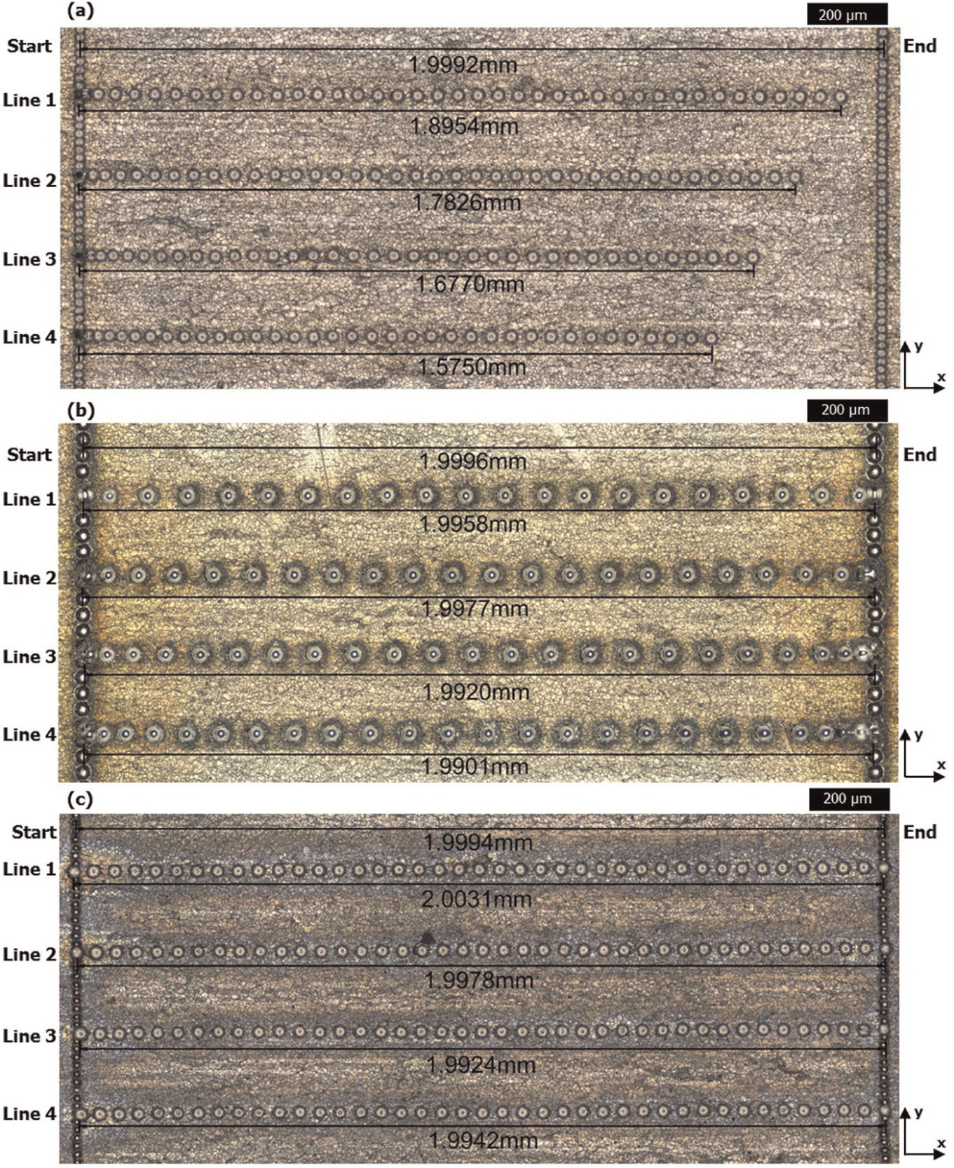
Validation tests with single pulse craters’ lines: (a) Trial 1 – machined lines along x-axis without the postprocessor; (b) Trial 2 – machined lines along x-axis without the postprocessor, but with optimised scanner and laser delays and (c) Trial 3 – machined lines along x-axis after applying the postprocessor.
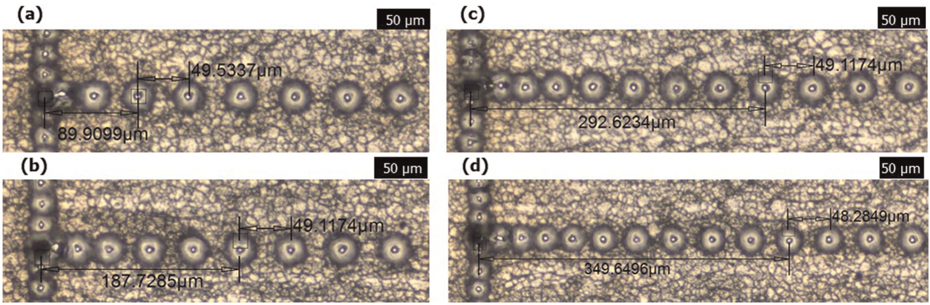
Acceleration region lengths in Trial 1 and Trial 2 produced at scan speeds of (a) 0.5 m/s, (b) 1 m/s, (c) 1.5 m/s and (d) 2 m/s.
The results from the single pulse craters’ lines.
SD: standard deviation.
Passive microwave filter
The laser machining results of the waveguide are shown in Figure 16, while Table 3 summarises the accuracy achieved in Trials 2, 3 and 4. The measurement uncertainty is again judged to be less than 2 μm based on the conducted 10 measurements for the Feature 1 width. The structure produced in Trial 1 demonstrates the inability of the laser machining process to deliver the required level of dimensional accuracy at high processing speeds. This is due to the negative dynamics effects of the used beam deflection system that result in waveguide channels that are significantly narrower than the programmed nominal dimensions, and also important functional features are not produced (see the CAD model in Figure 13 for reference). In particular, the necessity to execute machining vectors with micro-scale lengths (up to 80 μm) while the acceleration length is more than four times longer (∼350 μm at scan speed of 2 m/s) is the reason for inability of the laser machining process to deliver the required level of resolution and dimensional accuracy. Trial 2 demonstrates that through some optimisation of beam deflection system and laser delays, the machining error can be reduced to obtain a satisfactory dimensional accuracy. For example, Figure 17(a) and (b), which depicts Feature 1 of the waveguide, shows that the deviation of the produced structure is within ±10 μm from its nominal dimensions. However, the machining quality in Trial 2 is still not satisfactory even after the introduction of the delays due to varying pulse distances and hence non-uniform ablation rates in the acceleration and deceleration regions of machining vectors. Thus, the depth profile of the produced structures has a convex shape as shown in Figure 17(c) and (d). The accumulated effect of the applied 15 layers and the normal orientation of the machining vectors to the waveguide length result in a four times higher depth along the edges of the structure in comparison to that in its centre. Thus, even after optimising the delays in Trial 2, it is not possible to meet the quality requirements for the manufacture of the waveguide filter.
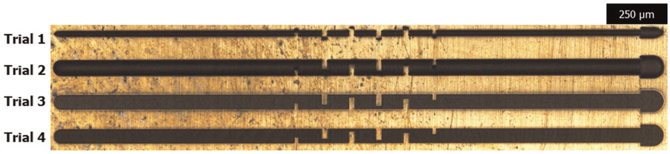
The waveguide structures produced in the four laser machining trials.
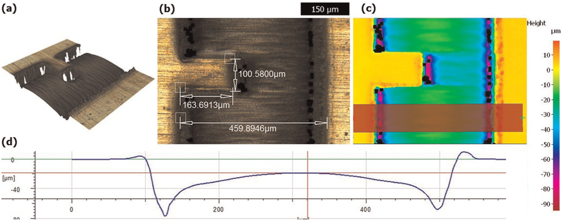
Feature 1 of the produced waveguide channel in Trial 2: (a) 3D view of the feature, (b) top view of the feature with some measurements and (c) and (d) the depth profile of the produced waveguide channel.
In Trial 3, the laser machining of the waveguide was carried out after applying the adaptive postprocessor. The machining results demonstrate clearly the postprocessor capabilities to offset the negative effects of the beam deflection system dynamics and thus to improve both dimensional accuracy and quality of the machined structure at high process speed. Figure 18(a) and (b), which shows Feature 1 of the microwave filter, clearly demonstrates that the deviation of the waveguide dimensions from their nominal values is within ±10 μm. Furthermore, the machining quality is improved dramatically by maintaining the pulse distance constant throughout the full length of machining vectors to achieve uniform material ablation across the waveguide channel as shown in Figure 18(c) and (d).
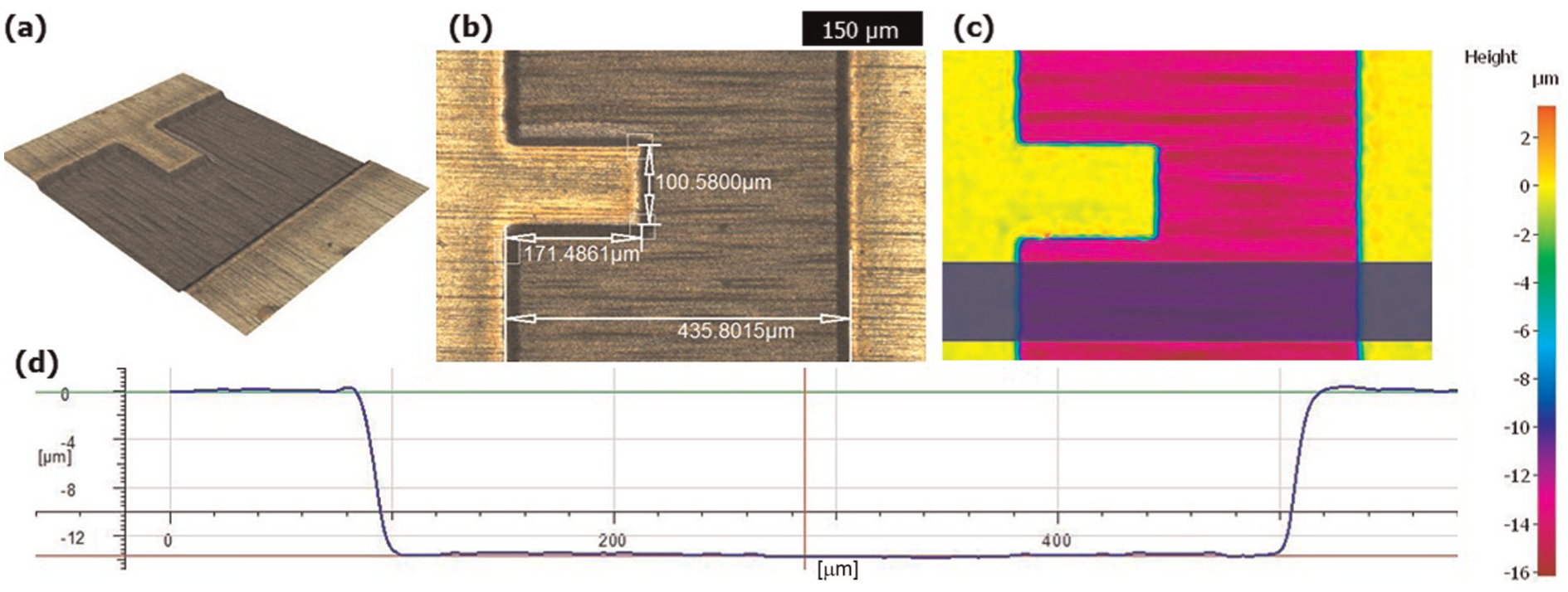
Feature 1 of the produced waveguide channel in Trial 3: (a) 3D view of the feature, (b) top view of the feature with some measurements and (c) and (d) the depth profiles of the produced waveguide channel.
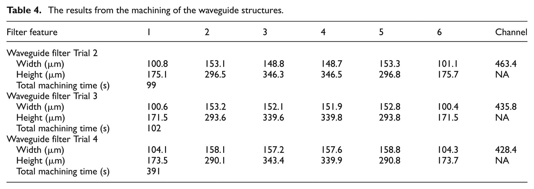
The machining accuracy and quality achieved in Trial 4 were almost the same as in Trial 3, but the laser machining efficiency in Trial 3 was significantly better in comparison to Trial 4. In particular, the machining time for the fabrication of the waveguide in Trials 3 and Trial 4 was 102 and 391 s, respectively (see Table 4). Thus, an almost fourfold efficiency improvement can be achieved if the adaptive postprocessor is utilised due to the applied high scan speeds. Furthermore, beam diameter compensations in Trial 4 were manually introduced to the CAD model in order to achieve the required machining accuracy that had time implications in generating the beam path.
The results from the machining of the waveguide structures.
Finally, it should be noted that the two different experimental validation tests demonstrate that the proposed software tools for offsetting the negative effects of the beam deflection system dynamics can be implemented with laser sources that have different control architectures.
Conclusion
This article presents a generic software solution to minimise the dynamic effects of beam deflection systems and to improve significantly the laser machining accuracy and efficiency. These improvements are achieved by implementing an ‘adaptive’ postprocessor as a stand-alone software. In this way, the generation of machine executable part programs is fully automated and users can benefit from these software tools regardless of their knowledge and experience with any given LMM systems. The capabilities of the proposed tool were validated experimentally. The following conclusions could be drawn from this research:
The dynamics effects of beam deflection systems integrated into LMM systems lead to significant machining errors and have a detrimental effect on the quality of produced structures, and this negative impact increases with the increase in the scan speed.
Such dynamic effects can be minimised by introducing machine-specific compensations in machining vectors to counteract their acceleration and deceleration regions regardless of their directions, length and set scan speed. Thus, laser machining with micro-scale machining vectors can be performed while maintaining a higher ARR.
The proposed software tool leads to substantial improvements in machining quality because uniform ablation rates can be maintained throughout the full length of machining vectors.
The use of the proposed software tool increases the laser machining efficiency substantially by allowing much higher scan speeds to be applied without any detrimental effects on ARR and machining quality.
Footnotes
Acknowledgements
The authors would like to acknowledge the University of Birmingham investment in setting up the laser micro-processing facilities used in this research. The authors would also like to acknowledge Delcam for providing the software for implementing the proposed adaptive postprocessor and for their valuable advice for its successful implementation.
Declaration of conflicting interest
The authors declare that there is no conflict of interest.
Funding
This study was financially supported by the following three research programmes: the FP7 HYPROLINE (High performance Production line for small series metal parts) project (contact no. 314685), the Interreg IVB NWE ECO-LASERFACT (ECO-efficient LASER technology for FACTories of the future) project and the Korea Government ‘Development of Next Generation Multi-Functional Machining Platforms for eco/bio Components’ project.