
Abstract
Fluid jet polishing is an enabling ultra-precision machining technology, which has not only been widely used for removing machine tool marks in order to achieve super finished surfaces, but also for controlling the form accuracy in machining freeform surfaces. Due to the complex machining mechanism, it is difficult to model the material removal rate accurately with consideration of a lot of operational parameters in fluid jet polishing. In this article, the optimal operational parameters and the significance of the important parameters are determined by the Taguchi design of experiments. Hence, a computational fluid dynamics–based analysis is built for the determination of the material removal rate in fluid jet polishing. In this model, the impact information of the particles with respect to the workpiece is computed by computational fluid dynamics simulation which is then coupled with a local mechanics erosion model so as to predict the detailed distribution of the material removal rate in fluid jet polishing. To verify the computational fluid dynamics–based erosion model, a series of polishing experiments have been conducted. The experimental results are found to agree well with the predicted form error and the pattern of the material removal rate by the integrated erosion prediction model.
Keywords
Introduction
The fabrication of complex shaped freeform surfaces made of hard and difficult-to-machine materials has always been a challenge for the optics industry. Computer-controlled ultra-precision polishing (CCUP) is an enabling technology which has become more widely used in super finished freeform surfaces made of difficult-to-machine materials.1–3 Fluid jet polishing (FJP) is a one of the promising CCUP technologies which makes use of an inclined adjustable nozzle to guide premixed slurry to the workpiece at appropriate speeds4,5 (see Figure 1). In recent years, FJP has not only been used for removing tool marks in order to achieve super finished surfaces but also been used for controlling the form accuracy of such surfaces. 6 In the FJP system, the material removal mechanisms are influenced by several process parameters as can be seen in Figure 2. It is stated that the cutting mechanics and materials’ removal of FJP are based on the collisions and shearing actions between the abrasive particles and the workpiece.7,8 Although our understanding of the complex mechanisms of material removal is still far from complete, there is a need to establish the theoretical model for determination of the material removal characteristics, which plays an important role in simulating the surface generation accurately and manufacturing the designed surfaces deterministically in FJP.
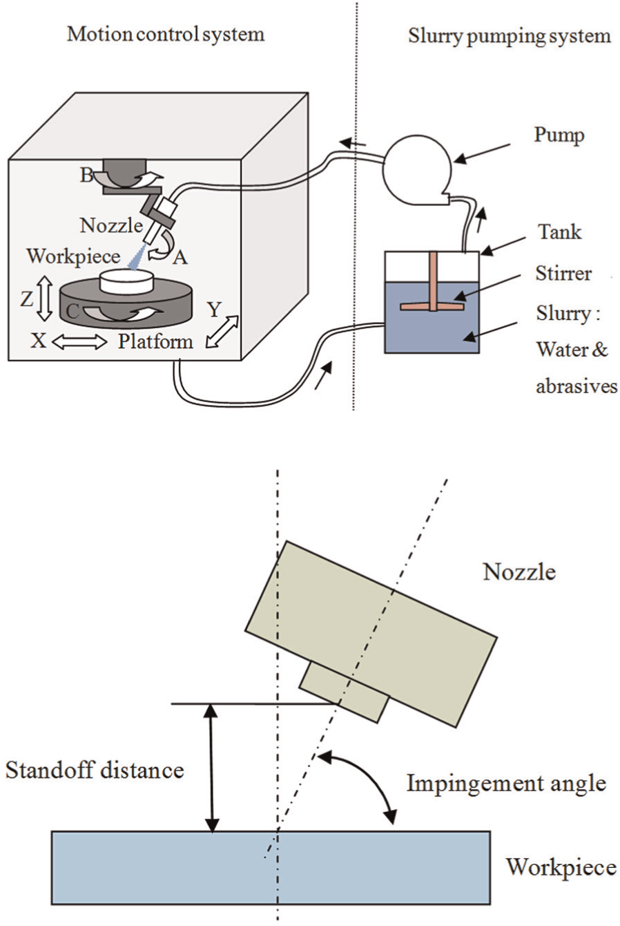
Schematic illustration of fluid jet polishing.
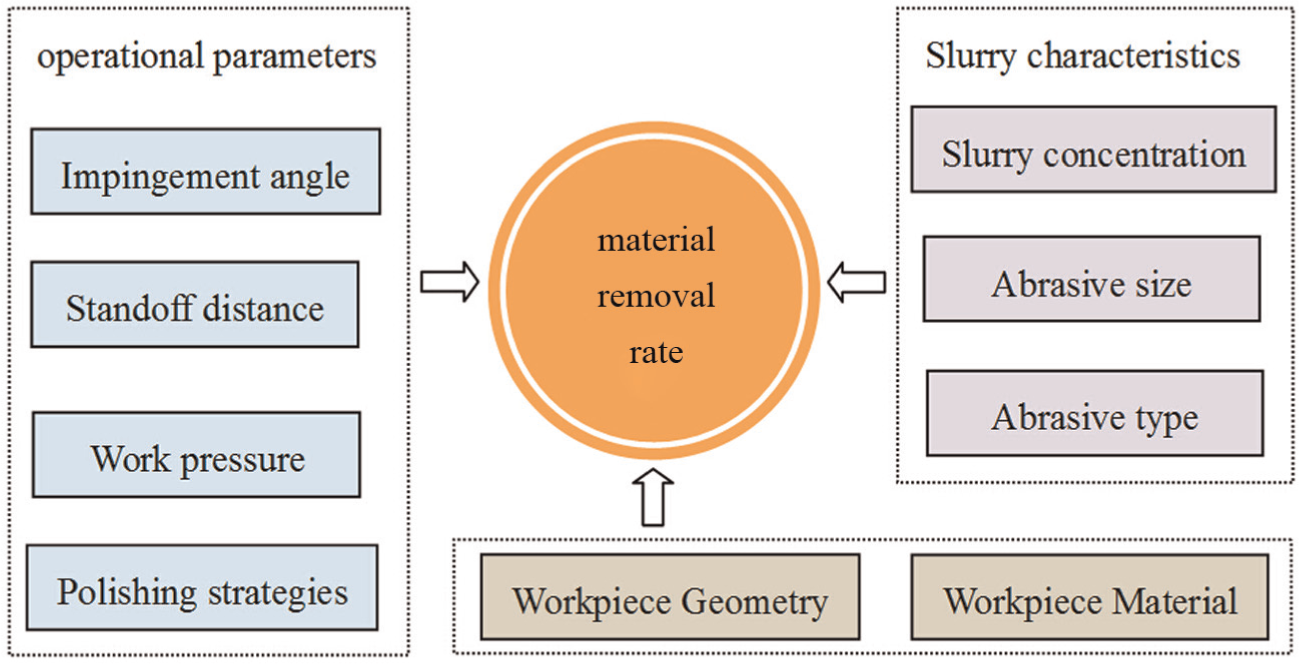
Factors affecting the material removal in fluid jet polishing.
Finnie 9 pioneered the derivation of a single-particle erosive cutting model and set the basic pattern and tone for all single-particle models. Finnie’s model shows reasonable agreement with the experimental data for ductile samples at shallow angles of attack. However, it underestimates the weight loss at large angles of attack considerably and predicts no material removed by vertical attack on such materials. Bitter10,11 developed an erosion model assuming that erosion phenomena are simultaneously caused by deformation wear and cutting action. Since then, a number of single-particle models have been proposed based on Finnie’s and Bitter’s models. However, most of the erosion models are delivered in dry conditions without considering the effect of fluid dynamics. For FJP, the material removal mechanisms depend not only on the material properties of the workpiece and the nature of the particles but also on the conditions under which the particles impact the workpiece. As a result, the determination of particle trajectories to obtain the information of impact velocity, impact angle and particles concentration distribution on the eroding surface area of the workpiece has been the key point in relation to predicting the material removal characteristics.
To solve this problem, computational fluid dynamics (CFD) is found to be a viable approach to understand the jet dynamic characteristics because direct measurement of particle velocities and visualization of particle trajectories are very difficult for FJP.
12
Wang
13
established particle velocity models based on the understanding and analysis of jet dynamic characteristics from a CFD simulation study. Narayanan et al.
14
also studied the fluid dynamics using a three-dimensional (3D) numerical simulation with the Ansys Fluent CFD solver. But these studies tend to be applications of CFD analysis in abrasive jet technology with ultra-high jet velocity and different flow fields. Li et al.
6
used a mixture model and the standard
Up to now, there is still a lack of developed deterministic models that consider all these operational parameters, so as to predict the material removal rate accurately. As a result, in order to further understand the effects of process parameters on the material removal in FJP, the Taguchi design experiments were conducted to identify the optimal operational parameters’ setting and the significance of the important parameters. Moreover, this article also describes the development of a comprehensive approach using CFD together with erosion model and experimental research to predict the detailed material removal characteristics in FJP.
CFD-based erosion modelling for FJP
In the FJP process, particles are accelerated by the drag force of water to impact on the workpiece repeatedly. They can be considered flexible machining tools which facilitate material removal at the nano-scale. As a result, the study of material removal characteristics in FJP can be divided into two sections. The first section focuses on the computation of relative motion between the workpiece and the particles while the modelling of erosion rate for impact particles is performed in the second section.
CFD modelling of the relative motion between the workpiece and particles
An Eulerian–Eulerian–Lagrangian method, which treats the water and air as Eulerian phases and the particles as Lagrangian particles, is described in this article. The coupled discrete phase model (DPM) and volume of fluid (VOF) model are used to describe the multiphases in FJP. This article also presents the use of the transport equation for the shear stress transport (SST)
Dynamic flow description
The impacted slurry in the vertical FJP process can be assumed to be a two-dimensional, incompressible, steady axisymmetric turbulent flow with constant properties and temperature conditions. 16 This turbulence flow field can be established by solving the Reynolds averaged Navier–Stokes (RANS) equations
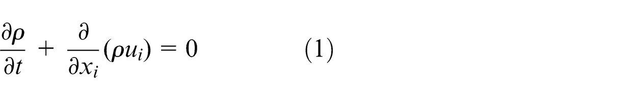
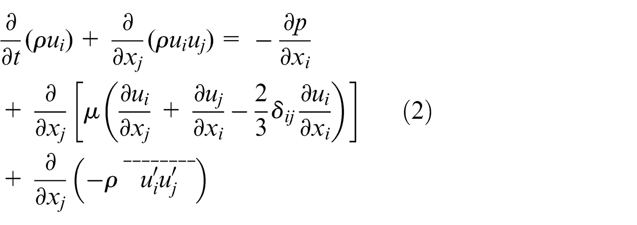
where
Turbulence flow description
In the RANS equations, the turbulent correlation for Reynolds stresses should be modelled in order to close the RANS equations. In this study, the SST
Multiphase flow description
The VOF model and the level-set method are popular interface-tracking techniques used to simulate the evolution of the interfaces between the slurry and air. The level-set method can assess the interface curvature and surface tension force exactly. 19 However, it is not efficient in accurately maintaining the volume conservation of the immiscible phases. On the contrary, the VOF model is effective in preserving volume conservation. 20 The limitation of the VOF model is that the computation of the interface curvature and surface tension is inaccurate because of the discontinuity of the VOF function across the interface. To avoid the limitations of both methods, the Coupled Level-Set and VOF Model are used to describe the multiphase systems and the interface according to the Fluent 13.0 Theory Guide. 18 In the present numerical simulation, air is treated as primary phase and surface tension is added as well for a correct evaluation of all the forces acting on the jet surface.
Lagrangian particle phase
In order to calculate the detailed information of the interaction of the particles and workpiece, the particulate phase is modelled using the Lagrangian description rather than the Eulerian method. In this study, particle–particle interactions are considered negligible and the particulate phase does not affect the prevailing flow field which has been shown to be a valid assumption by Chen et al. 21 A Lagrangian description of the particulate phase is based on a force balance around individual particles accounting for particle drag, gravitational force and additional forces (virtual mass force, Saffman’s lift force and pressure gradient), as shown in equation (3). The effect of the fluid turbulence on the particle motion is accounted for using a discrete random walk model as referred to by Wallace et al. 22
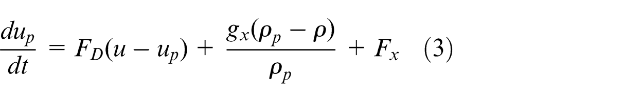
where
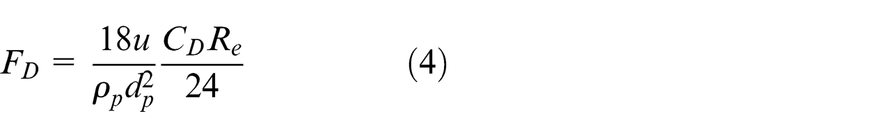
where
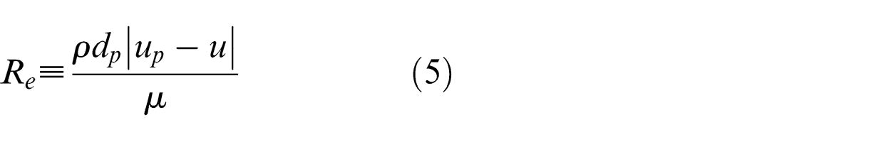
In the simulation model, each particle is tracked separately through the flow field and particle impact information (velocity and location) is gathered as particles strike the wall.
Boundary conditions and other numerical settings
The geometry of the computational domain with boundary conditions is shown in Figure 3. Inlet boundary condition is specified by the velocity-inlet entering the nozzle. It is assumed that the velocity at the INLET is uniform across the cross section. The CFD simulation starts where the slurry enters the computational domain through the boundary of the INLET and ends after the jet exits the fluid domain from the boundary of the OUTLET. Pressure outlet boundary condition was set at the OUTLET, with the surrounding pressure of 0 bar gauge. The established CFD model was run with higher-order discretization schemes and a pressure implicit with splitting of operator (PISO) scheme for pressure–velocity coupling. The interface sharpening routine applied for the VOF model is Geo-reconstruct. The solution initialization is computed from all zones with the default turbulence kinetic energy and specific dissipation rate and the water volume fraction is set to 0. The rest of the numerical settings were selected to obtain the best results in terms of simulation convergence and accuracy, as suggested in the Fluent 13.0 User’s Guide. 23
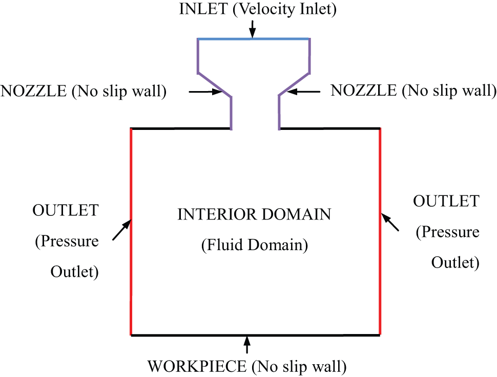
Computation domain and boundary conditions of the CFD model.
Erosion models for the prediction of material removal profile in FJP
Impact information of the particles (impact velocity
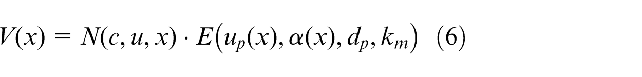
where
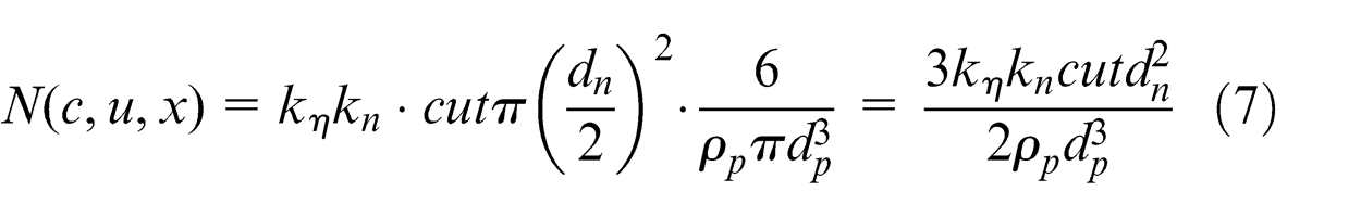
where kη is the effective impact factor, kn is the proportional factor, t is the machining time and dn is the nozzle diameter. Although most of the erosion models are developed for predicting the erosion rate caused by a single particle and delivered in dry conditions without considering the effect of fluid dynamics, these models can be regarded as the framework of reference for CFD-based erosion modelling and an attempt was made to extend the application of existing single-particle erosion models with consideration of velocity distribution and abrasive particle spatial distribution so as to predict the detailed material removal profile in FJP. To further implement and evaluate the prediction capabilities of CFD-based erosion modelling, a range of different ductile-mode erosion models are used and modified in the following sections.
Finnie’s erosion model
In Finnie’s erosion model, Finnie 9 considered the erosive effect of translation in the vertical and horizontal directions, regardless of rotation of the particle. The predicted amount of material removal has a quadratic relationship with the impact velocity of particles, as expressed in equations (8) and (9)
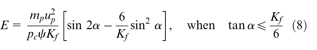
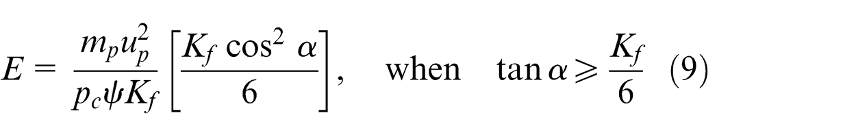
where
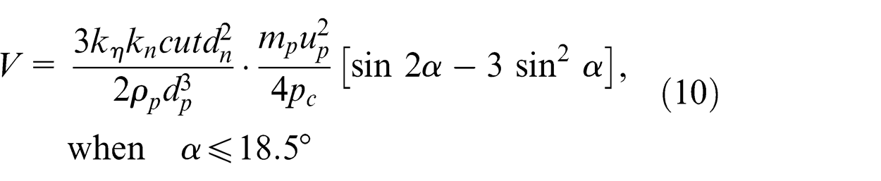
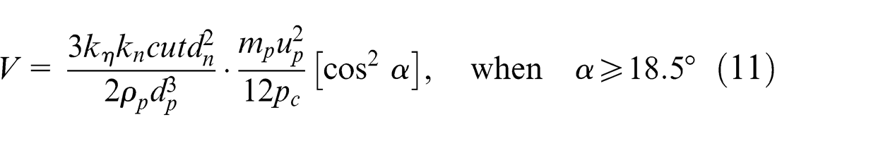
Bergevin–Nesic-modified Finnie model
Due to the poor performance of Finnie’s model in sudden axisymmetric pipe expansion, Bergevin and Nesic proposed a modification of Finnie’s erosion model by introducing a critical impact velocity. 24 The volume removed by a single-particle impact is expressed using the following equations
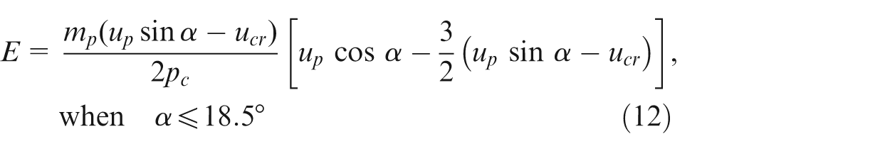
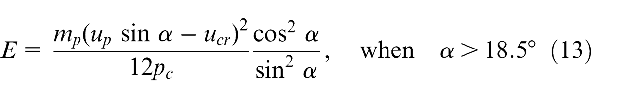
where
Erosion model of Huang et al
Huang et al. 25 developed a mechanical erosion model considering the factors of impact velocity, impact angle, particle size and the material properties of the workpiece. In their model, two force components, the tangential force and normal force, were separately described as having different roles in the material removal mechanisms. This model has been used together with CFD models to predict the erosion26,27
where EB
, σB
and εB
are the stiffness, hardness and ductility of the target material, respectively. B = EB
/Ep
is defined as the stiffness ratio between the eroded material and the particle. C and D are the coefficients which depend on the materials. Substituting equations (7) and (16) into equation (6) and using
Experimental description and discussion
The experiments are divided into two groups, that is, Group A and Group B. The experiments in Group A aim to study the factors affecting the removal rate for FJP. Hence, optimal process parameters and the significance of operational parameters are determined and verified for the FJP. The results of Group A are used for establishing the experimental conditions for the experiments in Group B. In Group B, experiments are conducted to verify the CFD-based erosion modelling for FJP.
Apparatus and materials
As shown in Figure 4, the polishing machine used in this study was a Zeeko IRP200 ultra-precision freeform polishing machine, with three linear axes and three rotational axes. The slurry nozzle is assembled on the main spindle (but does not rotate), while the workpiece is fixed on the C axis. The current polishing tests were performed using optical glass BK7. Due to the material properties such as transparency and reflectance of BK7, the workpiece was measured by a contact type Form Talysurf profiler system from Taylor Hobson Ltd, UK. These specimens were polished using aluminium oxide (Al2O3) slurry.

(a) Zeeko IRP200 ultra-precision freeform polishing machine and (b) the setup configuration.
Group A: design of experiments for the optimization of process parameters
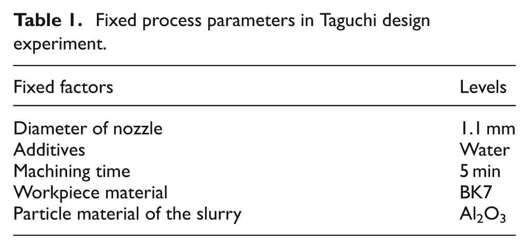
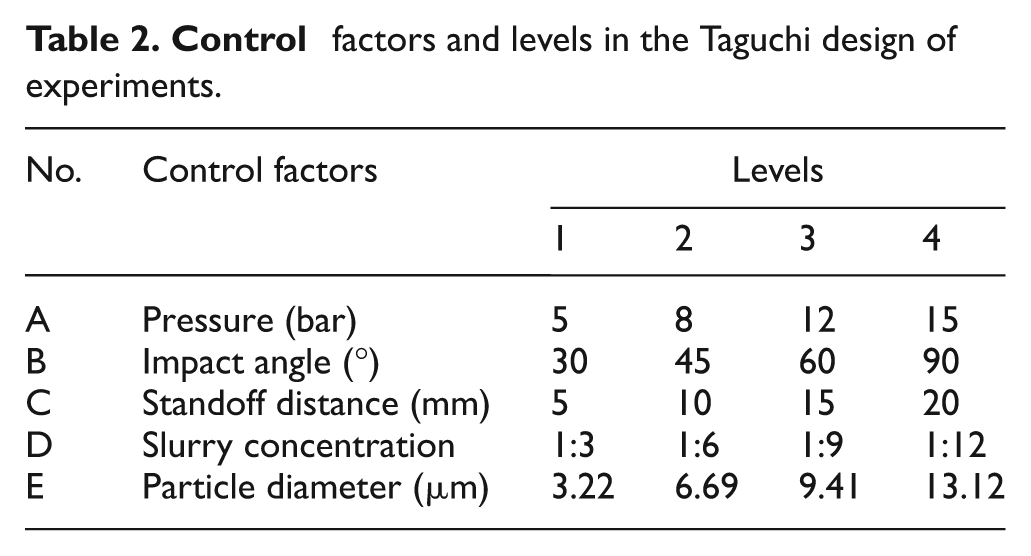
As an ultra-precision finishing process, FJP is commonly used to remove the tool marks to obtain super finished mirror surface. However, recent study tends to apply FJP for form correction so as to achieve corrective polishing. It is interesting to note that the material remove rate is also an important criterion for FJP considering time efficiency and surface quality improvement. Hence, the Taguchi method is used to design the experiments to investigate the effect of the factors on the material removal rate. The material removal characteristics are commonly described as a tool influence function and assessed in terms of width, maximum depth and volume of material removal rate. In this study, the material removal rate is quantified in terms of the maximum depth of material removal in FJP. The experiments were conducted using the five fixed process parameters and the five control factors (each with four levels), as shown in Tables 1 and 2, respectively. Accordingly, the Taguchi design method was configured using a double orthogonal array, in which the five control factors were arranged in an L16(45) orthogonal array.
Fixed process parameters in Taguchi design experiment.
Control factors and levels in the Taguchi design of experiments.
Experimental results for Group A
Optimal process parameters
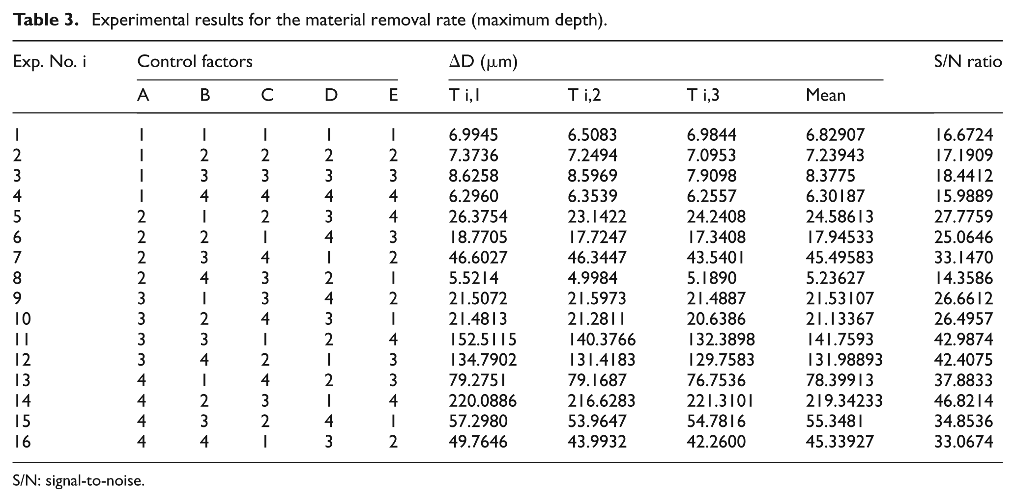
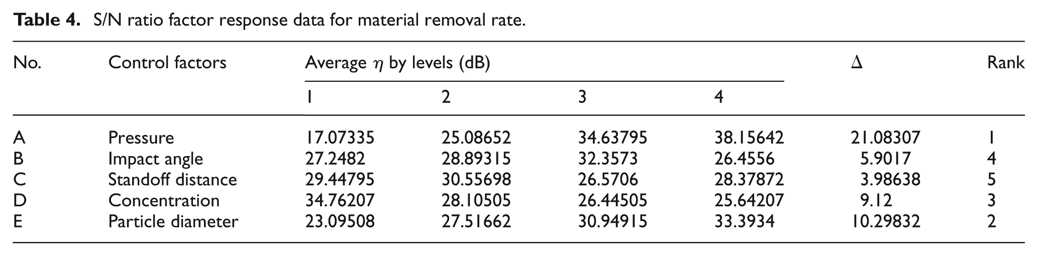
The Taguchi method provides an effective tool for optimizing the operational parameters with a minimum number of experimental trials. 2 Furthermore, the optimal process parameters determined by the Taguchi trials tend to be robust to unavoidable variations in the environmental conditions, or other forms of external noise. In these experiments, a higher-the-better signal-to-noise (S/N) ratio was used and a larger S/N ratio infers that the corresponding factor level setting provides a larger material removal rate in FJP. Table 3 summarizes the Taguchi experimental results and the determination of the mean value and the S/N ratio. The S/N ratio data of each of the five experimental variable factors at every level are presented in Table 4. As shown in Table 4, it is interesting to note that the pressure has the largest effect on the material removal rate, and that standoff distance has the smallest effect. Figures 5 and 6 show the plots of the S/N ratios and means for the material removal rate in graphical form, respectively. The main effects plot for the S/N ratios indicate that the factor level combination which ensures the optimal material removal rate is under the combination of the experimental conditions of A4B3C2D1E4. However, the main effects plot for the means shows that the combination of the optimal factor level for the material removal rate is A4B2C3D1E4. As shown in Figure 5, the impact angle (factor B) and standoff distance (factor C) have very little influence on the S/N ratio. Since they have an insignificant effect on S/N, it is the perfect choice for the mean adjustment factor. The main effects plot for the means indicates that shifting impact angle and standoff distance to a higher level increase the material removal rate but does not affect S/N distinctly. As a result, the combination of the optimal factor level for the material removal rate should be A4B2C3D1E4.
Experimental results for the material removal rate (maximum depth).
S/N: signal-to-noise.
S/N ratio factor response data for material removal rate.
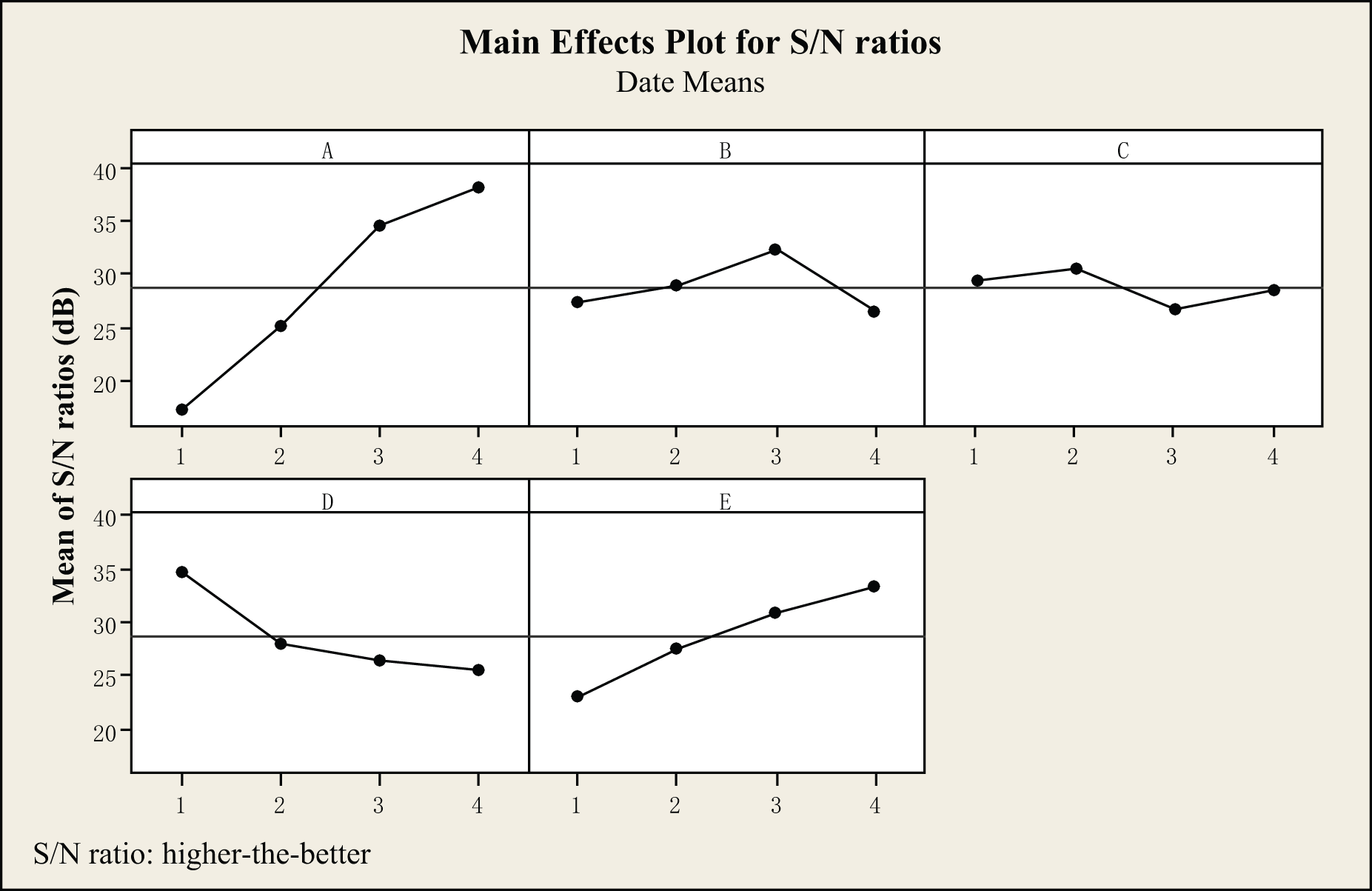
S/N ratio factor response graphs for the material removal rate.
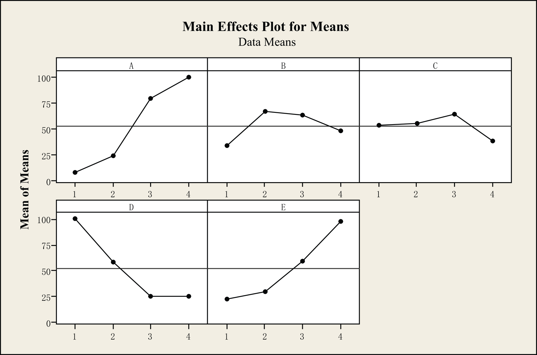
Mean factor response graphs for the material removal rate.
Confirmatory experiments
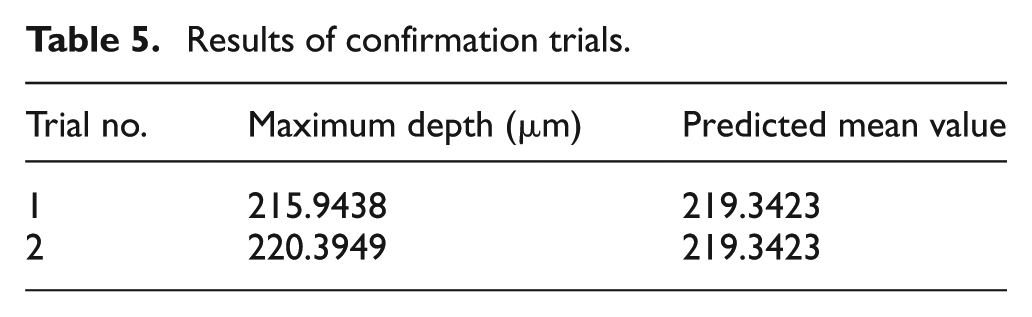
To confirm the reliability of the Taguchi experiments, two polishing experiments were performed under the optimal operational parameters obtained from the Taguchi designed experiments. The results of the confirmatory experiments are presented in Table 5. It is interesting to note that a very slight discrepancy is observed between the predicted material removal rate and the experimental data. However, the overall results of the confirmation trials indicate that the optimal factor level combination of A4B2C3D1E4 provides a consistent material removal rate in FJP. In other words, the optimal process parameters are given as pressure of 15 bar, impact angle of 45°, standoff distance of 15 mm, slurry concentration of 1:3 and particle size of 13.12 μm, when the BK7 workpiece material was polished using a 1.1-mm-diameter nozzle, pure water additives and Al2O3 abrasive particles.
Results of confirmation trials.
Group B: validation experiments for the CFD-based erosion modelling
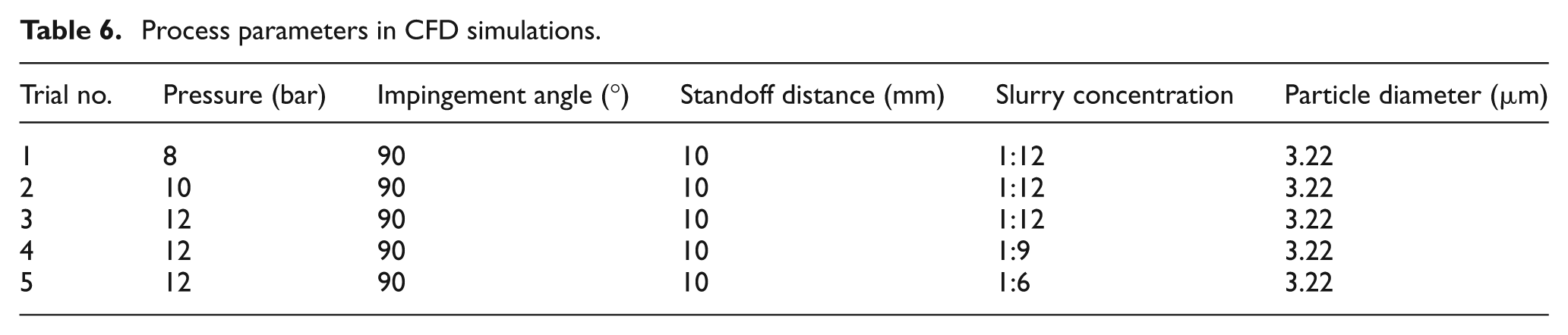
In this study, a series of CFD simulations are constructed under the same conditions that are adopted for experiments (see Table 6). The results of the simulation (in the case of 10 bar) can be seen in Figure 7. As shown in Figure 7(a), the blue area represents the Al2O3 slurry and red area represents the surrounding air in FJP. Figure 7(b) shows the distribution of pressure in the FJP process, which states that high pressure focuses on the shrinkage aperture of the nozzle and the impact area between the slurry and the workpiece. Figure 7(c) shows the distribution of the velocity in the FJP process, which indicates that the velocity is increased in the shrinkage area of the nozzle and arrives at a maximum when the slurry jets out of the nozzle. A relatively small velocity occurs at the centre of the impact area. Although the dynamic characteristics of particles are random in the slurry, due to the overall statistical properties, Figure 7(d) shows the concentration distribution of the CFD simulation in a given moment. It is interesting to note that the concentration distribution tends to be different at any given time.
Process parameters in CFD simulations.
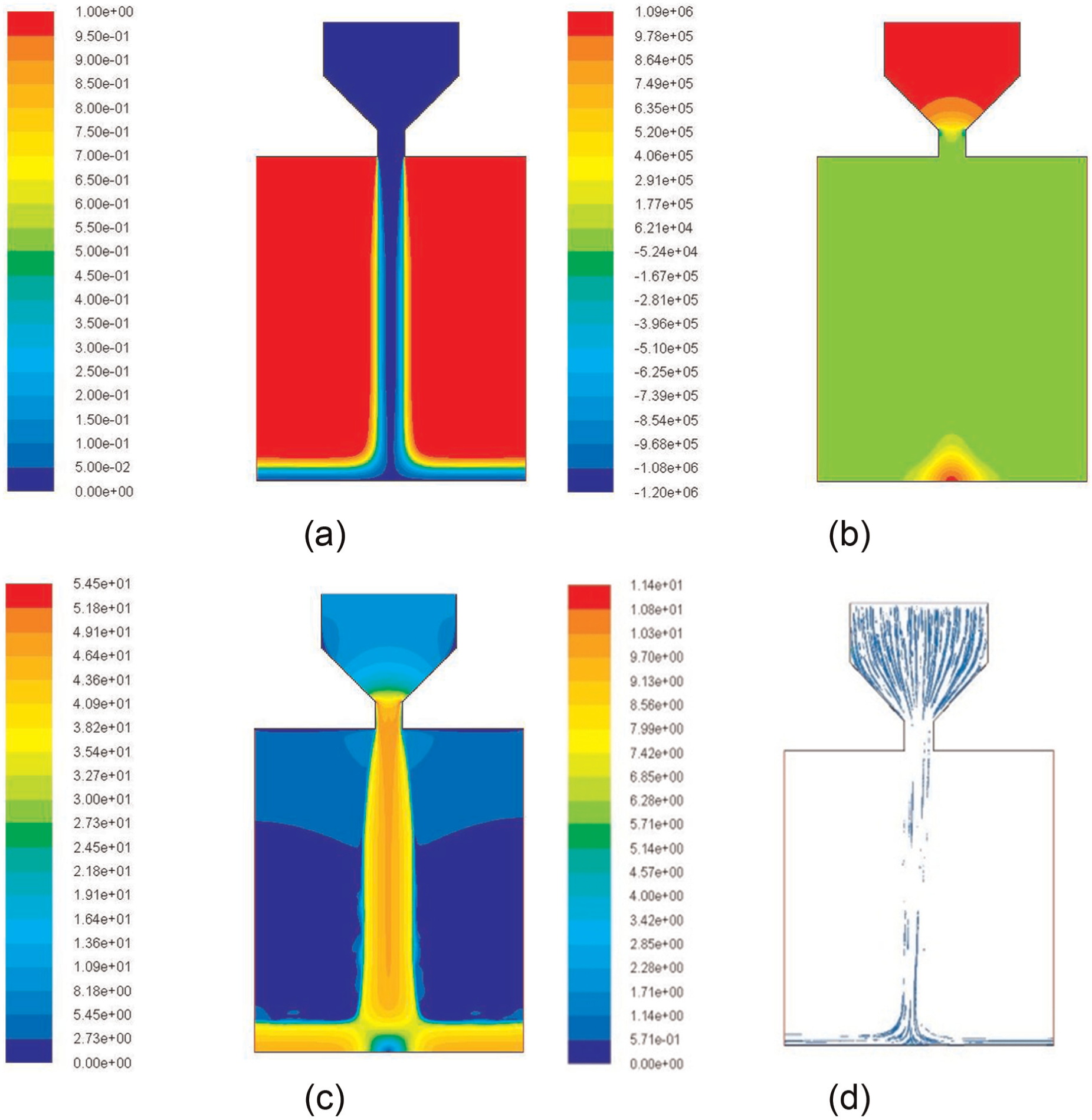
(Colour online) Distribution of normal impact fluid field (for case of 46.5447 m/s): (a) phase field, (b) pressure field (Pa), (c) velocity field (m/s) and (d) concentration field (kg/m3).
Figure 8 shows the 3D topology of the material removal rate of experimental data and CFD-based erosion modelling using different erosion models (in the case of 8 bar). It is interesting to note that the results of CFD-based erosion modelling employing Finnie’s model, the Bergevin–Nesic (B–N) model and Huang et al.’s erosion model show good correlation with the experimental data. The results show the feasibility and effectiveness of the CFD-based erosion model to predict the detailed material removal profile in FJP.
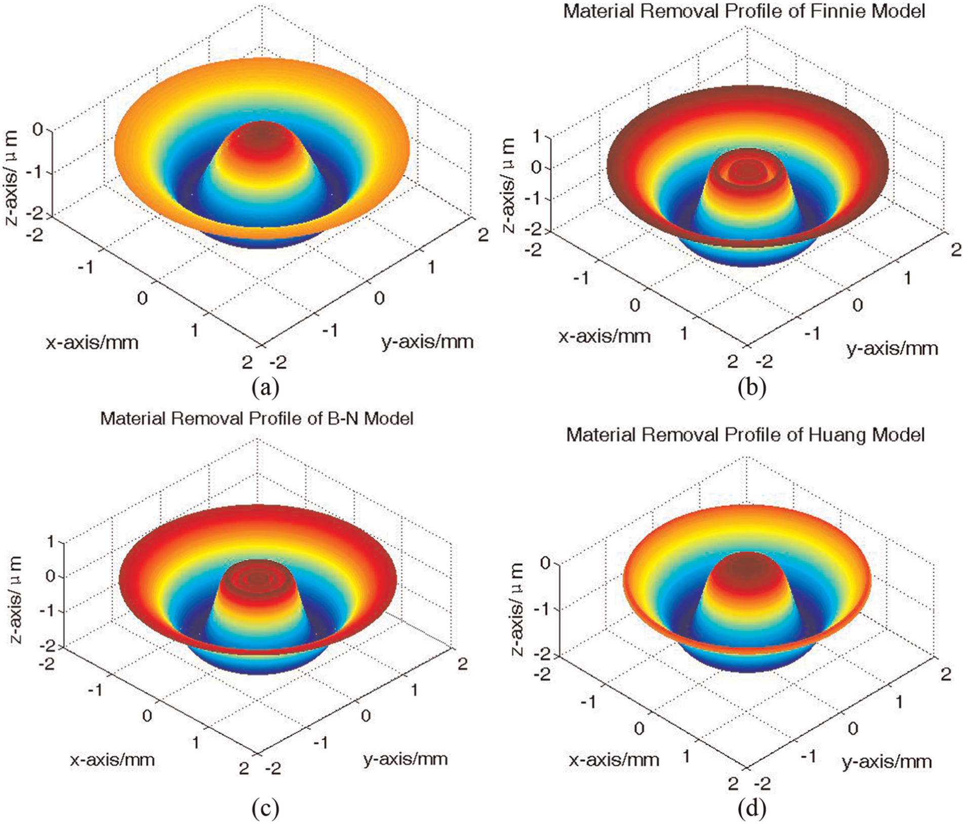
3D topology of material removal rate of CFD-based erosion modelling (for case of 8 bar): (a) experimental data, (b) Finnie model, (c) Bergevin–Nesic model and (d) Huang erosion model.
To further illustrate the qualitative comparison of the material removal profile from the experimental measurement using Form Talysurf and from the CFD simulations with the typical erosion models, Figure 9 shows the results using differently shaped and coloured curves in the unified coordinate system. It is found that the results of CFD-based erosion modelling based on the Finnie model and B–N erosion model show good agreement with the measured data at low impact angle (the position range of
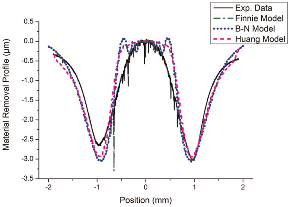
A qualitative comparison of the material removal profile from experimental measurement using Form Talysurf and from the CFD simulations with the modified erosion models.
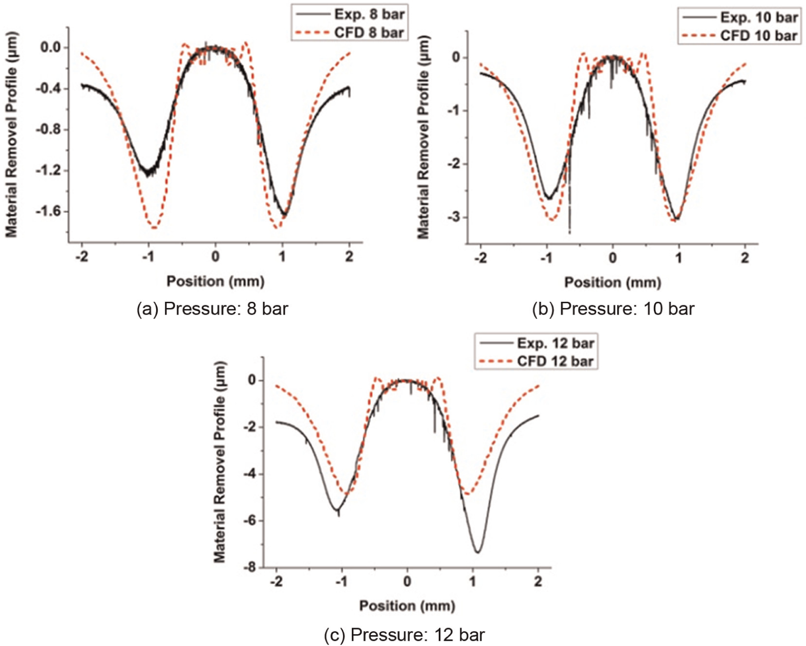
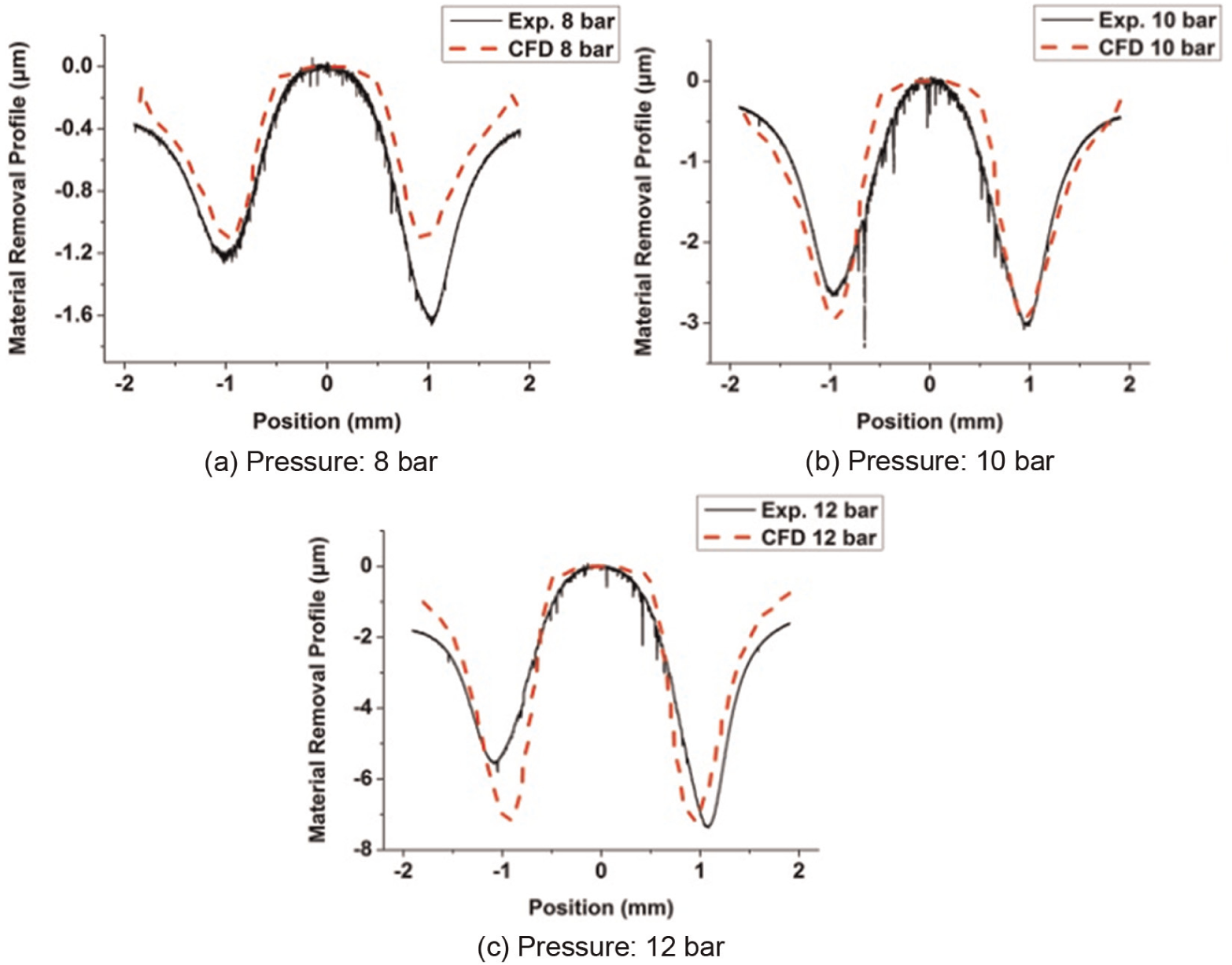
To test the robust performance of CFD-based erosion modelling, impact data, obtained from CFD simulations under the different work pressures of 8, 10 and 12 bar, were used together with the various existing erosion models (in section ‘Erosion models for the prediction of material removal profile in FJP’) to predict the detailed material removal profile. Different shapes of material removal profile under the various work pressures were measured by a contact type Form Talysurf profiler system from Taylor Hobson Ltd. Figures 10–12 indicate that the CFD-based erosion modelling using the Huang model has higher robustness than the CFD-based erosion modelling based on the Finnie model and B–N erosion model under various work pressures. Moreover, the Finnie model and B–N erosion model have similar predictive ability when used in the CFD-based erosion modelling. It can be inferred that the exponential of the impact velocity of particles, which is greater than 2 in erosion model, may have better predictive precision for CFD-based erosion modelling.
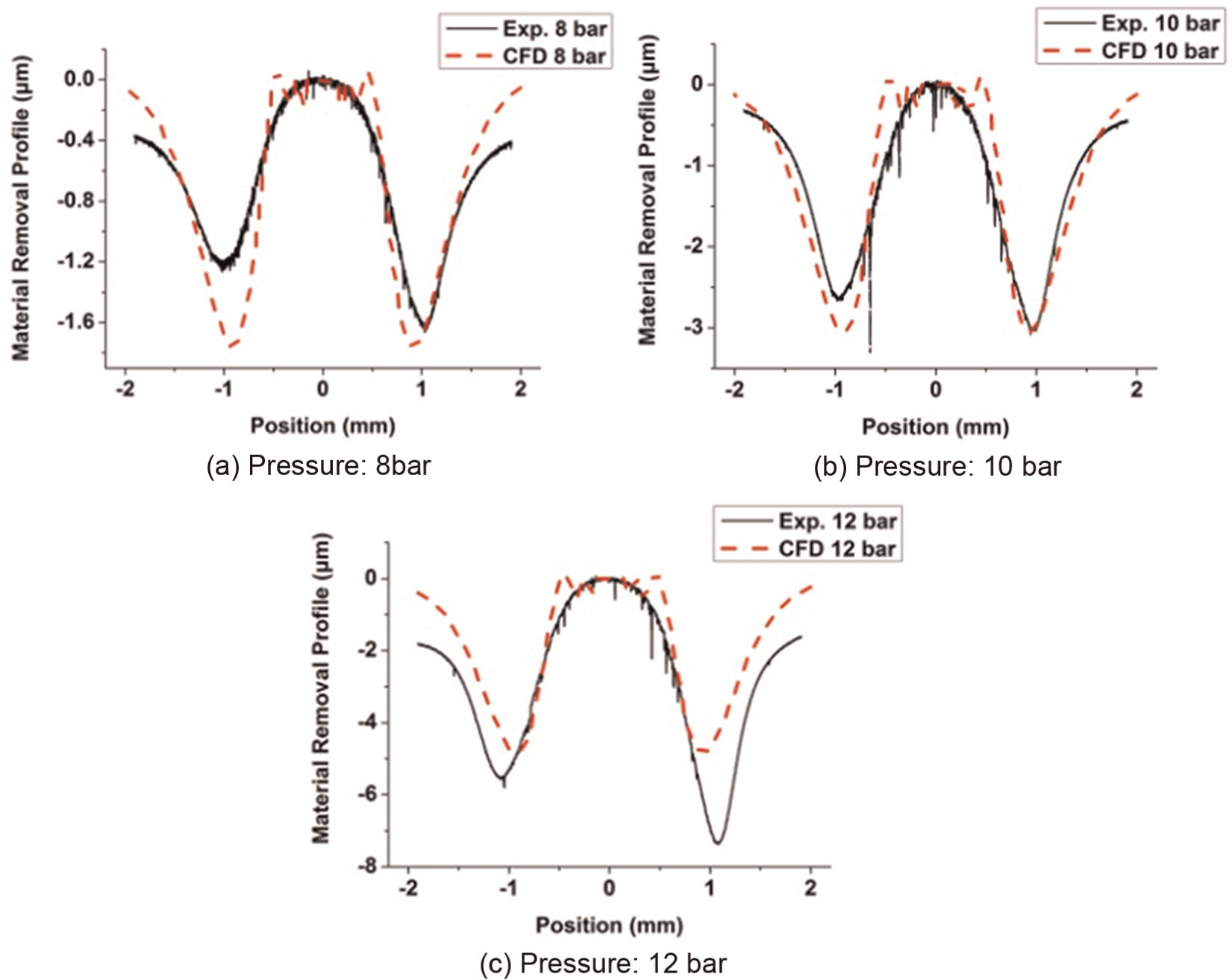
A qualitative comparison of the material removal profile from experimental measurement and from the CFD modelling based on modified Finnie erosion model under various work pressures.
A qualitative comparison of the material removal profile from experimental measurement and from the CFD modelling based on modified B–N erosion model under various work pressures.
A qualitative comparison of the material removal profile from experimental measurement and from the CFD modelling based on modified Huang erosion model under various work pressures.
It is interesting to find that the shape and depth of the material removal profile vary with the changing work pressure and the predicted results of CFD-based erosion modelling show good agreement with the experimental data. In Figure 13, the variation in the material removal characteristics predicted by CFD-based erosion modelling is consistent with that obtained from experiments. This infers that the modified term in the erosion model is correct. The slight deviation of the material profile predicted by the CFD-based erosion modelling may be caused by the difference of pressure setting between the CFD simulation and the experiment, the instability of the pump system, the surface inclination of the workpiece or the abrasion of the nozzle.
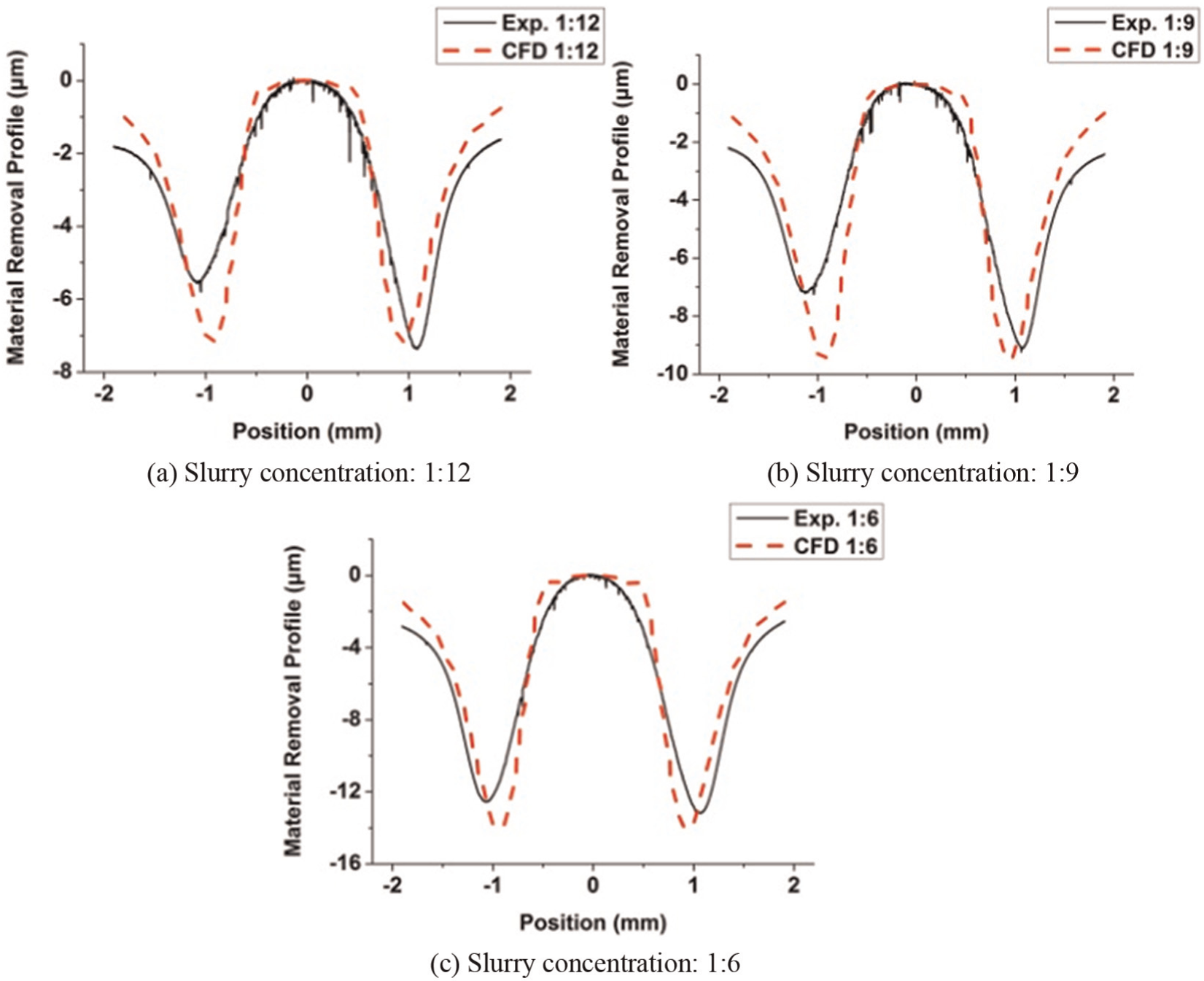
A qualitative comparison of the material removal profile from experimental measurement and from the CFD-based erosion modelling using Huang erosion model under various slurry concentrations.
As a result, an integrated erosion prediction model was established based on the combination of CFD simulations, erosion model and experimental research. It was found to be able to predict the detailed material removal characteristics in FJP. Although the comprehensive erosion prediction approach proposed in this study was found to be technically feasible and effective in predicting the detailed material removal characteristics in FJP, a more accurate erosion model incorporating some other important factors should be further investigated and established to achieve higher performance in CFD-based erosion modelling under various polishing conditions.
Conclusion
Due to the complex machining mechanism, it is difficult to model the material removal characteristics accurately with the consideration of all operational parameters. This study made use of the Taguchi design experiments to identify the optimal operational parameters and the significance of the important parameters. The Taguchi trials show that the pressure has the largest effect on the material removal rate, and that standoff distance has the smallest effect. Moreover, the results of the Taguchi design process indicate that the optimal process parameters are given as follows: pressure of 15 bar, impact angle of 45°, standoff distance of 15 mm, slurry concentration of 1:3 and particle size of 13.12 μm, when polishing BK7 using a 1.1-mm-diameter nozzle, pure water additives and Al2O3 abrasive particles.
Furthermore, a CFD-based erosion model for the prediction of the material removal characteristics in FJP was developed. In this study, modelling and simulation of material removal characteristics in FJP were established using the combination of CFD, erosion model and experimental study. First, the hydrodynamic conditions and trajectories of particles in the slurry were computed and simulated using the CFD code. Hence, the data obtained from the CFD simulations were used together with the erosion model to predict the detailed material removal profile, while some empirical constants contained in the erosion models were determined by experiment.
To test the accuracy and robustness of the CFD-based erosion modelling using different modified erosion models, a series of experiments were conducted under various work polishing conditions such as pressure and slurry concentrations. It is interesting to note that the shape and depth of material removal profile vary with the variation in the work pressure, and the predicted results of CFD-based erosion modelling show good agreement with the experimental data. Moreover, CFD-based erosion modelling using the Huang model has higher robustness than CFD-based erosion modelling based on the Finnie model and B–N erosion model under various work pressures. Moreover, the variation in the material removal characteristics as predicted by CFD-based erosion modelling based on Huang et al.’s model is consistent with that obtained from the experimental results obtained under various slurry concentration conditions. As a result, the integrated erosion prediction model, established by a combination of CFD simulations, erosion model and experimental research, was found to be able to predict the material removal characteristics in FJP. Although this study shows the technical feasibility and effectiveness of the CFD-based erosion model, a more accurate erosion model incorporating some other important factors should be investigated and established to achieve higher performance of the CFD-based erosion model under various polishing conditions.
Footnotes
Declaration of conflicting interests
The authors declare that there is no conflict of interest.
Funding
The work described in this article was fully supported by a grant from the Research Grants Council of the Government of the Hong Kong Special Administrative Region, China (Project No.: PolyU 5132/11E). The authors would also like to express their sincere thanks to the Research Committee of The Hong Kong Polytechnic University for the financial support for the project (Project Code: RTC3).