
Abstract
This article developed a three-dimensional finite element model of cryogenic minimum quantity lubrication machining in order to investigate the role of cooling/lubrication effect of cryogenic minimum quantity lubrication in machining of AISI H13 steel. In this model, the cryogenic cooling effect provided by refrigerated compressed air is modeled with a convective heat transfer coefficient. A heat transfer window with the temperature and convective heat transfer coefficient of refrigerated compressed air was defined on tool face and workpiece, respectively, which could move at the same speed as cutting tool so as to simulate continuous cryogenic cooling process of cutting zone under cryogenic minimum quantity lubrication condition. The temperature of refrigerated compressed air was set at −10 °C, −30 °C, −50 °C, −100 °C, and −140 °C to study the influence of cryogenic cooling effect of cryogenic minimum quantity lubrication. Frictional contact between tool and chip was modeled with a simple constant shear stress model. Comparative simulations were conducted under different cooling/lubrication conditions, those are, dry cutting, refrigerated compressed air, and cryogenic minimum quantity lubrication. The simulation results show that both cryogenic cooling effect and lubrication effect resulted in reduction in cutting force and tool temperature when machining AISI H13 steel under cryogenic minimum quantity lubrication condition. With a decrease in temperature of refrigerated compressed air, cutting force and tool temperature did not decrease continuously. The reduction in cutting force, maximum tool temperature, and average temperature of rake face and flank face at low and high cutting speeds was strongly attributed to the cryogenic cooling effect and lubrication effect provided by cryogenic minimum quantity lubrication, respectively. A significant reduction in cutting force and tool temperature was caused by the improvement in lubrication effect provided by cryogenic minimum quantity lubrication irrespective of the cutting speed. The trends revealed by the simulations provide helpful information for the development of this technique.
Keywords
Introduction
In modern metal cutting operations, high heat generation and intense friction between tool and chip drastically reduce tool life.1,2 Cutting fluids are traditionally used at low pressure and high quantities to reduce the temperature and friction in the cutting zone. Unfortunately, conventional cutting fluids cause environment, health, and machining cost problems.3,4 In addition, the usage of conventional cutting fluids is not so effective at high cutting speed due to the fact that cutting fluids supplied using conventional delivery technique fail to penetrate into the region adjacent to the cutting edge. 5 For reducing production costs and ecological loads, some new techniques for cooling and lubricating cutting zone, such as minimum quantity lubrication (MQL), refrigerated gas cutting, and cryogenic minimum quantity lubrication (CMQL), have been proposed and studied.
CMQL is a kind of green cooling/lubrication technique, which consists of the application of a small amount of lubricant (6–100 mL/h), delivered in a refrigerated compressed air stream to the cutting zone. It is similar to MQL except that it uses the refrigerated compressed air. Thus, CMQL can compensate the low cooling capacity of MQL technique. In recent years, CMQL machining processes of different materials have been reported by some researchers.6–10 Ko et al. 6 designed a CMQL cooling system based on the principle of air vortex flow and used the CMQL cooling method for turning of hardened steel. The results showed that with the CMQL cooling method, the life of TiN-coated tool was 30% that of cubic boron nitride (CBN) cutting tool. Su et al. 7 studied the effect of CMQL (−20 °C) during finish turning of Inconel 718 nickel-based super alloy and found that refrigerated compressed air stream (−20 °C) and CMQL presented 78% and 124%, respectively, improvement in tool life over dry cutting. In addition, they also investigated the effect of CMQL (−20 °C) on cutting force and tool wear in high-speed milling of titanium alloys by coated carbide inserts. The results indicated that as compared with dry milling and refrigerated compressed air stream (−10 °C and −20 °C), there was a considerable reduction in cutting force and tool wear for CMQL. 8 Bian et al. 9 studied the machinability of high-strength stainless steel under different cooling/lubrication conditions and reported that compared with dry milling, the tool life by using MQL and CMQL increased by 43.4% and 80%, respectively. Zhang et al. 10 investigated the effect of CMQL (−30 °C) on tool wear and cutting force variations in end milling of Inconel 718 with coated cutting tools. The results suggested that the cutting force and tool wear under CMQL condition were much lower than those under dry cutting condition. From the studies listed above, it can be seen that CMQL may enhance the machining performance of some difficult-to-cut materials remarkably due to its superior cooling/lubrication effect.
Understanding the influence of cooling/lubrication effect of CMQL on machining process is the key to developing and applying this technique properly. However, until now, studies regarding CMQL cutting seem to be still confined to experimental investigation. It is difficult to analyze the role of cooling/lubrication effect of CMQL in a wide range of CMQL parameters due to the limitations of experimental conditions. Finite element method (FEM) has qualified as an excellent way to explore machining process, which aids researchers to investigate cutting mechanics. Currently, some researchers have used this method to study several environment-friendly machining techniques. For instance, Lopez de Lacalle et al. 11 assessed the efficiency of MQL flow and conventional emulsion coolant in high-speed milling of wrought aluminum alloys through computational fluid dynamics (CFD) simulation. Shet et al. 12 developed a finite element (FE) model of high-pressure water-jet-assisted orthogonal cutting, in which water jet was injected directly into the tool–chip interface through a small hole on the rake face of the tool. The effect of water jet hole position and pressure in machining of AISI 4340 steel was investigated by FE simulations in their work. Courbon et al. 13 simulated high-pressure jet-assisted turning of Inconel 718 on a whole pressure range (50–130 MPa) using the Arbitrary Lagrangian–Eulerian (ALE) numerical model in the commercial code Abaqus. In their simulation, the jet was injected at the tool–chip interface via an external nozzle. Zhao et al. 14 developed a two-dimensional (2D) FE model for the enhanced cooling cutting of Ti–6Al–4V alloy using a commercial FE software DEFORM-2D, in which the enhanced cooling effect was modeled with a convective heat transfer coefficient assigned to a heat transfer window of cutting zone, and analyzed the influence of different enhanced cooling effects on cutting force and cutting temperature. Sun et al. 15 proposed a novel smart cutting tool with a closed internal cooling system for dry cutting and performed the simulations using software ANSYS and FLUENT to investigate the efficiency of cooling process and optimize the cooling structure of the tool. For optimizing the spraying conditions of oil mist and reducing the oil consumption, Obikawa et al. 16 conducted CFD analysis of oil mist flow in MQL finish turning of Inconel 718 using cutting tools with three types of nozzles. An et al. 17 investigated flow field and droplets’ characteristics of MQL in external thread turning based on CFD method and from CFD simulation results revealed the reasons of good cooling and lubricating effects for MQL in the case of thread turning.
In this article, a three-dimensional (3D) FE model is presented using a commercial software DEFORM-3D to simulate cylindrical turning of AISI H13 steel under CMQL condition. The role of cooling/lubrication effect of CMQL in machining of AISI H13 steel is investigated by FEM cutting simulation.
FE model
Geometry, meshing, and boundary conditions
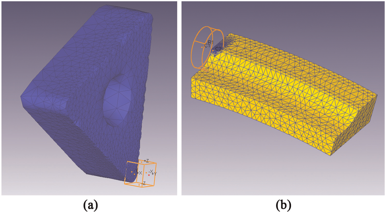
FE model of cylindrical turning was developed using updated Lagrangian (DEFORM-3D) software in which chip separation from workpiece was achieved by continuous remeshing. Figure 1 shows the general arrangement and mesh configuration for cylindrical turning process. The workpiece was represented by a curve model with 50 mm diameter and 15° arc angle. The cutting insert used in this model was the American National Standards Institute (ANSI) tool designation TNMA 332. The workpiece was fixed in all directions, and the cutting insert was rotated at the specified cutting speed. The workpiece was a rigid-plastic body, initially meshed with 15,000 elements, and the cutting insert was a rigid body meshed with 10,000 elements. As shown in Figure 2, the mesh windows, which could move with the cutting insert, were defined at the tip of cutting insert and at the cutting zone, and the size ratio of elements inside window to outside window was 0.05 for each mesh window. Thus, the mesh inside the windows was made denser to achieve fine process output distributions. The heat transfer coefficient at the tool–chip interface governs heat transfer from chip to cutting tool. Based on the research work of Umbrello et al., 18 it was taken as 100 kW/m2 K in this model to allow rapid temperature rise in the cutting insert so that steady-state thermal conditions in the cutting insert could be reached quickly.
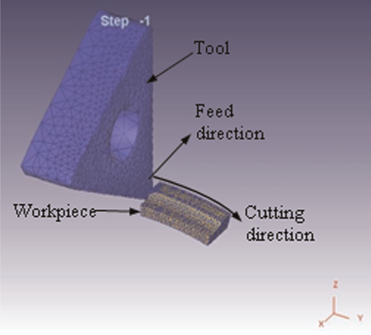
General arrangement and mesh configuration for cylindrical turning process.
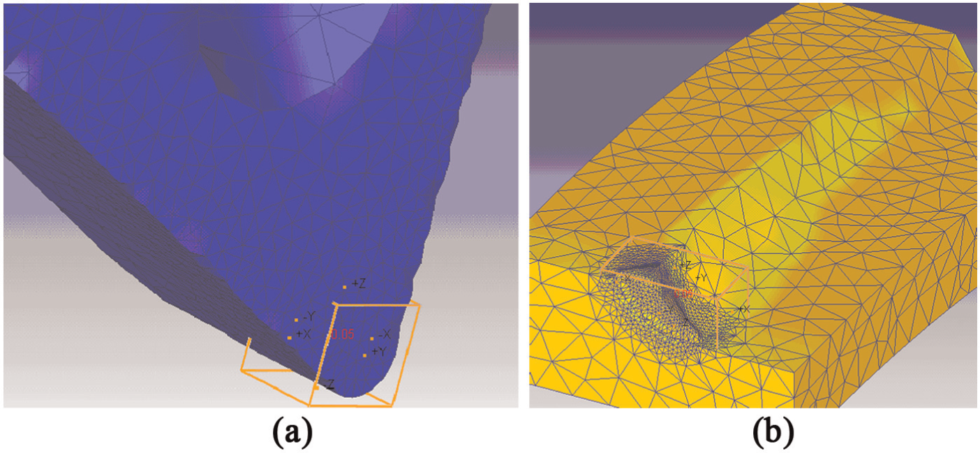
Mesh windows: (a) tool and (b) workpiece.
Material properties of workpiece and tool
The workpiece and tool material used in this model were AISI H13 tool steel and cemented carbide, respectively. AISI H13 tool steel with hardness of 40–55 HRC has been widely used in forging, extrusion, and die casting because of its high strength, high toughness, and wear resistance. To model the constitutive behavior of AISI H13 tool steel under high temperature, high strain, and high strain rate in machining process, a classical Johnson–Cook 19 constitutive law was employed, which can be represented by the following
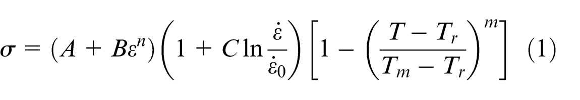
where
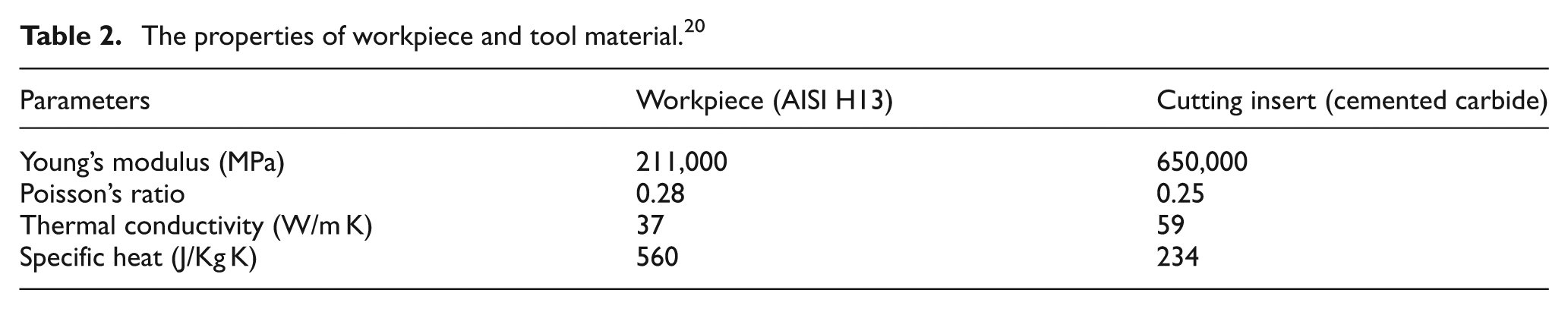
For modeling purposes, workpiece hardness was taken as 46 HRC. The J–C material constants of the workpiece adopted for AISI H13 tool steel are listed in Table 1, 20 whereas the mechanical and physical properties of both the workpiece and the cutting insert are obtained from Yan et al. 20 and DEFORM-3D software as given in Table 2.
Johnson–Cook material constants for AISI H13 tool steel. 20

The properties of workpiece and tool material. 20
Modeling of cooling effect
For CMQL cutting, temperature reduction at the cutting zone is achieved mainly by the cryogenic cooling effect of refrigerated compressed air and partially by the evaporation of lubricants. 21 Only cryogenic cooling effect provided by refrigerated compressed air was considered in modeling the cooling effect of CMQL for this simulation. The compressed air is refrigerated and then jetted to the cutting zone at a high pressure to dissipate the heat produced by the cutting process by means of heat convection. In this research, the cooling effect provided by refrigerated compressed air was modeled with a convective heat transfer coefficient, h, as given below

where q is the heat flux from the hot surface to the refrigerated compressed air, T is the object surface temperature, and T 0 is the temperature of refrigerated compressed air. It can be obviously seen from this equation that heat transfer flux depends on convective heat transfer coefficient and temperature of refrigerated compressed air. In order to study the influence of cryogenic cooling effect of CMQL on machining performance, the temperature of refrigerated compressed air was set at −10 °C, −30 °C, −50 °C, −100 °C, and −140 °C. According to the research works of Yang 22 and Luchesi and Coelho, 23 an approximate value of 100 W/m2 K was assigned to the heat transfer coefficient of refrigerated compressed air in this work. As shown in Figure 3, a heat transfer window with the temperature and convective heat transfer coefficient of refrigerated compressed air was defined on tool face and workpiece, respectively, which could move at the same speed as cutting tool so as to simulate continuous cryogenic cooling process of cutting zone under CMQL condition.
Heat transfer windows used to simulate the cryogenic cooling process under CMQL condition: (a) tool and (b) workpiece.
Friction modeling
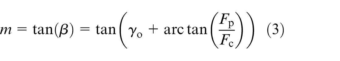
In this study, friction contact between tool and chip was modeled using a constant shear stress model in which a shear friction factor, m, is used to represent the friction at entire tool–chip interface. For dry cutting and refrigerated compressed air, the applied shear friction factor was 0.6, which is usually adopted in steel cutting. In CMQL cutting, the fragmented micro-droplets of cutting oil with high speed are able to penetrate into the cutting zone where they perform their lubrication effect by forming boundary lubrication film and reduce the friction. A lot of research was carried out to study experimentally the effect of MQL and CMQL with different operating parameters on cutting force, cutting temperature, and tool wear in turning, milling, and drilling process. It was found that type of lubricant and spraying conditions of oil mist (air pressure and temperature, nozzle orientation and distance, and flow rate of lubricant) affect the lubrication effect of MQL and CMQL.24–30 In order to determine the shear friction factor under CMQL condition, turning experiments of AISI H13 tool steel were performed on a CA6140 lathe with the same simulation conditions employed by this article. The chosen cutting tools were cemented carbide inserts with ISO code TNMA 160408, manufactured by Sandvik Coromant. Refrigerated compressed air at a temperature of −20 °C was produced using the developed generator 7 and then brought to Accu-Lube MQL system through a thermally insulated hosepipe. An Accu-Lube LB2000 vegetable oil was employed as CMQL cutting oil, which is biodegradable and non-toxic. The CMQL oil mist was supplied by Accu-Lube MQL system through a single nozzle in an extremely small amount of flow rate (10 mL/h) at a pressure of 0.5 MPa. Nozzle orientation was a very important factor for the effective supply of oil mist. As pointed out by Ueda et al., 24 the horizontal and vertical angle of 45° was the best nozzle angle for oil mist to reach the tool–chip interface effectively, which was adopted in this experimental work (Figure 4). Nozzle distance from the cutting zone was kept constant at 30 mm. The friction factor at tool–chip interface can be calculated based on the following friction angle formulation 31
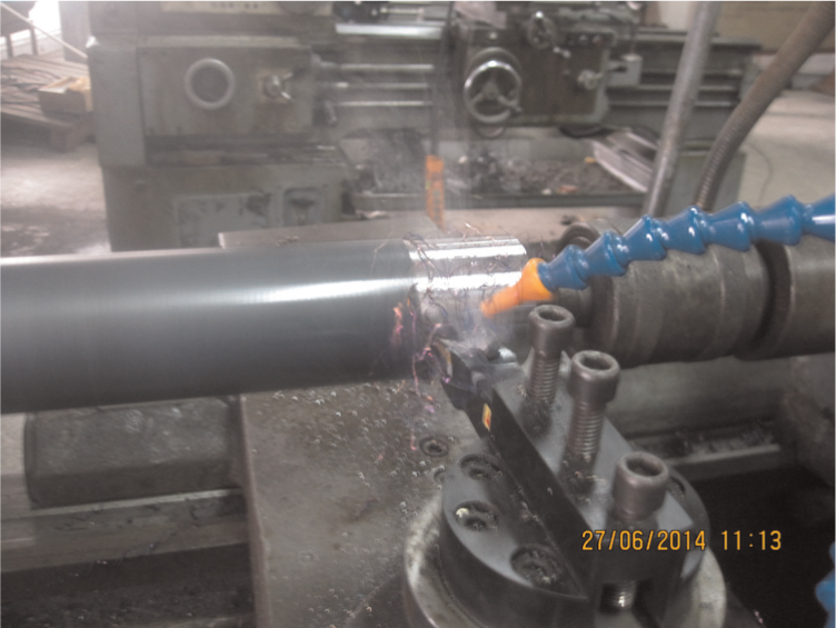
Nozzle orientation used in CMQL cutting process.
where β is the friction angle, γ o is the rake angle, F p is the thrust force, and F c is the main cutting force. Cutting force generated during CMQL cutting of AISI H13 tool steel was measured using a strain turning dynamometer. Based on the experimental results, the values of 0.55 and 0.53 were assigned to the shear friction factor for CMQL at the cutting speeds of 47 and 104 m/min, respectively. In addition, a shear friction factor of 0.5 was also used so as to study the influence of improvement of lubrication effect provided by CMQL on the machining performance.
FE simulation
FE analysis consisted of 20 simulations using two different cutting speeds (47 and 104 m/min) and three different cooling/lubrication conditions (dry cutting, refrigerated compressed air, and CMQL). Under dry cutting condition, heat losses to the environment are by means of natural convection heat transfer. A value of 10 W/m2 K was assigned to the heat transfer coefficient for dry cutting in this study. Detailed simulation parameters are given in Table 3. When simulating refrigerated compressed air and CMQL cutting of AISI H13 tool steel, the size and position of heat transfer windows on tool surface and workpiece were the same to ensure that heat transfer conditions were the same. The simulated machining time was more than 8 ms.
Detailed simulation parameters.
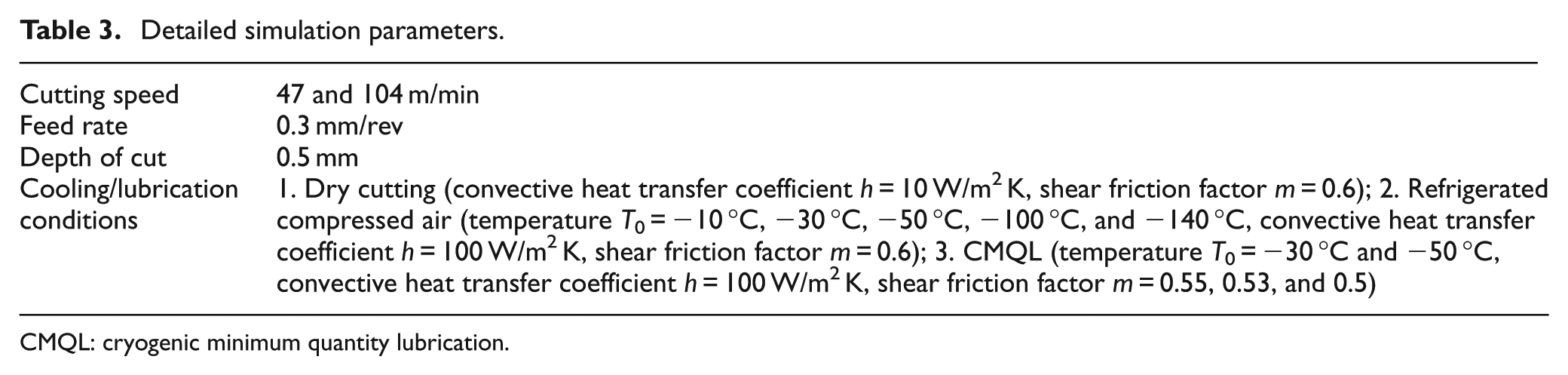
CMQL: cryogenic minimum quantity lubrication.
Simulation results and discussion
Effect of CMQL on cutting force
Cutting force is one of the important criteria by which machining performance can be assessed. Figure 5 shows a comparison of cutting force for dry cutting and refrigerated compressed air with different temperatures obtained from simulation. As shown in Figure 5, main cutting force, feed force, and thrust force under refrigerated compressed air condition were lower than those under dry cutting condition. Furthermore, three force components under refrigerated compressed air condition were found to be decreasing with the decrease in temperature of refrigerated compressed air up to −50 °C or −30 °C and after that those began to increase. Relative to dry cutting, the lower cutting force has been experimentally observed by Rahman et al. 32 and Ko et al. 6 in machining AISI P20 tool steel and heat-treated bearing steel (SAE 52100) using refrigerated compressed air, respectively. When using refrigerated compressed air in the machining of AISI H13 tool steel, cryogenic cooling effect provided by refrigerated compressed air strengthens the workpiece and reduces thermal softening, which increases cutting force. On the other hand, cryogenic cooling effect also reduces the toughness of workpiece, which reduces cutting force. The decrease in cutting force caused by reduced toughness of AISI H13 tool steel was reported by Broqvist et al. 33 Thus, the effect of cryogenic cooling provided by refrigerated compressed air on cutting force is a result of a reduction in the toughness of workpiece and an increase in the strength of workpiece. The balance between these two opposing effects will determine the final cutting force. It can explain the existence of an optimal temperature of refrigerated compressed air that provides a minimum cutting force, as seen in Figure 5.
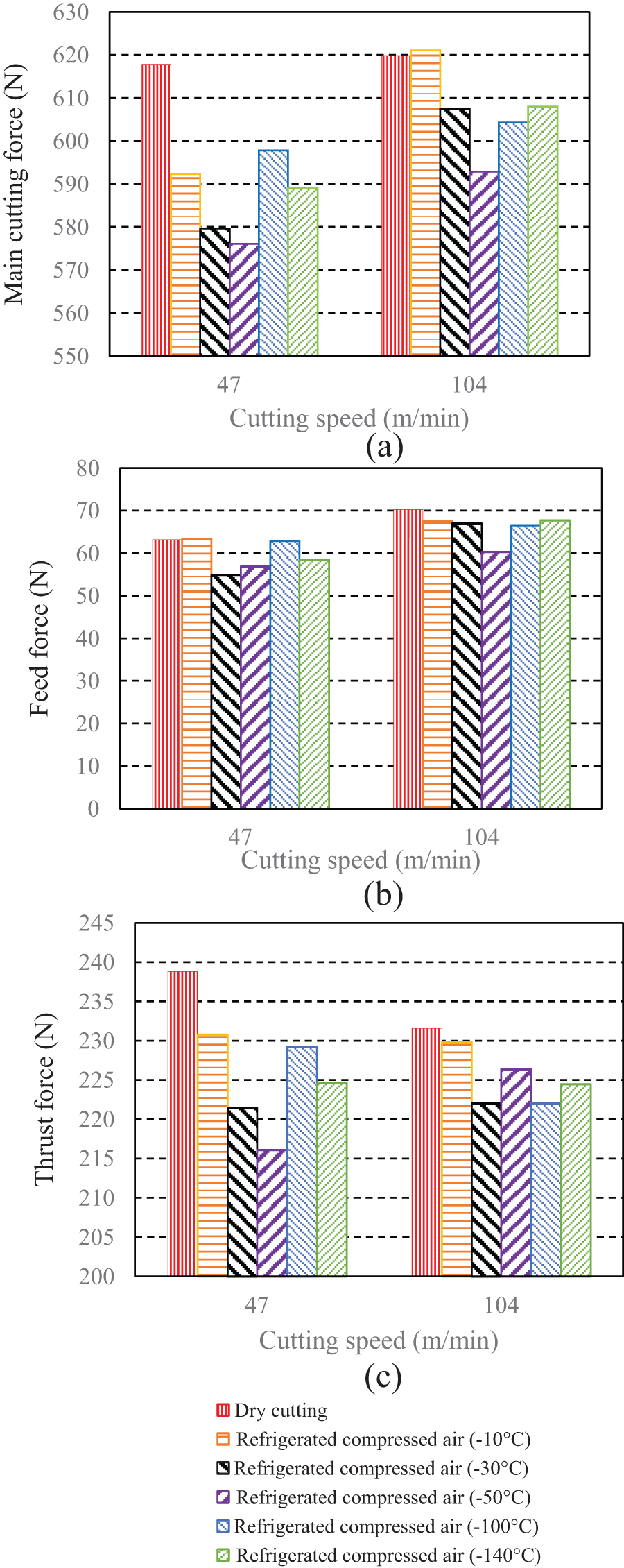
Comparison of cutting force for dry cutting and refrigerated compressed air with different temperatures obtained from simulation: (a) main cutting force, (b) feed force, and (c) thrust force.
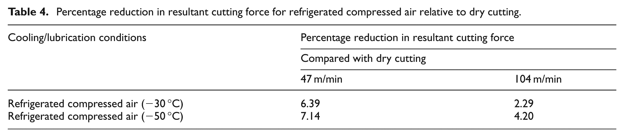
Furthermore, comparison of three force components among dry cutting, refrigerated compressed air, and CMQL conditions was given in Figure 6. It can be seen from Figure 6 that the forces from the least to the largest were in the order of CMQL (−30 °C or −50 °C, m = 0.5), CMQL (−50 °C, m = 0.55 or 0.53), CMQL (−30 °C, m = 0.55 or 0.53), refrigerated compressed air (−50 °C), refrigerated compressed air (−30 °C), and dry cutting conditions. In order to study the influence of cooling and lubrication effects provided by CMQL on cutting force by simulation, the resultant cutting force under dry cutting and refrigerated compressed air and that under CMQL and refrigerated compressed air were compared, respectively. Tables 4 and 5 show the percentage reduction in resultant cutting force for refrigerated compressed air relative to dry cutting and that for CMQL relative to refrigerated compressed air, respectively. Compared with dry cutting, the reduction in cutting force under refrigerated compressed air condition was due to the cryogenic cooling effect. In addition, compared with refrigerated compressed air, the reduction in cutting force under CMQL condition was due to the lubrication effect of CMQL. The comparative results clearly show that the percentage reduction in cutting force by cryogenic cooling effect was greater than that by the lubrication effect provided by CMQL at the cutting speed of 47 m/min, while the percentage reduction in cutting force by the lubrication effect provided by CMQL was almost the same as that by cryogenic cooling effect at the cutting speed of 104 m/min. This indicates that for CMQL cutting of AISI H13 tool steel, the cryogenic cooling effect provided by refrigerated compressed air was the dominant mechanism for the reduction in cutting force at low cutting speed, whereas at high cutting speed, the lubrication effect provided by CMQL played as important a role as its cryogenic cooling effect in terms of reduction in cutting force. Table 6 shows the percentage reduction in resultant cutting force resulting from improvement of lubrication effect provided by CMQL. When the shear friction factor under CMQL condition decreased from 0.55 or 0.53 to 0.5, an obvious decrease in resultant cutting force was obtained at both cutting speeds.
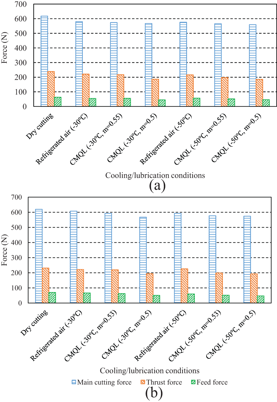
Comparison of three force components among dry cutting, refrigerated compressed air, and CMQL conditions: (a) 47 m/min and (b) 104 m/min.
Percentage reduction in resultant cutting force for refrigerated compressed air relative to dry cutting.
Percentage reduction in resultant cutting force for CMQL relative to refrigerated compressed air.
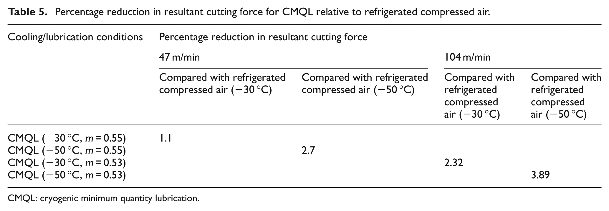
CMQL: cryogenic minimum quantity lubrication.
Percentage reduction in resultant cutting force resulting from improvement in lubrication effect provided by CMQL.
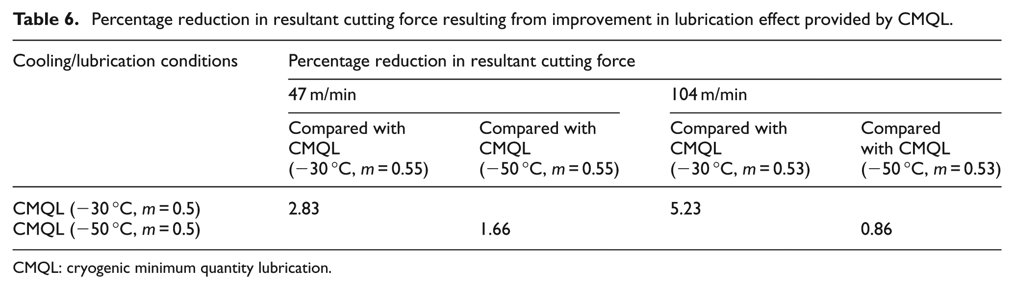
CMQL: cryogenic minimum quantity lubrication.
Effect of CMQL on cutting temperature
Cutting temperature is a key factor in machining operations which affects the tool wear greatly. Figure 7 shows the predicted steady-state tool temperature distribution at the cutting speed of 104 m/min obtained under dry cutting and refrigerated compressed air conditions. In each distribution, the maximum tool temperature is also indicated. It can be seen that the maximum tool temperature appeared near tool tip regardless of the cooling/lubrication conditions. The tool temperature distribution was not significantly influenced by the variation in the temperature of refrigerated compressed air, even when refrigerated compressed air with −140 °C was used, as shown in Figure 7. The maximum tool temperature, average rake temperature, and average flank temperature were used to evaluate the influence of cooling/lubrication conditions on tool temperature in this simulation. A series of points were defined on the rake face and flank face, respectively, and the mean value of their temperature was taken as average rake temperature and flank temperature, respectively, as illustrated in Figure 8. In order to ensure the effectiveness of evaluation, the number and position of the defined points on the rake and flank faces were the same for dry cutting, refrigerated compressed air, and CMQL. Figure 9 shows a comparison of tool temperature for dry cutting and refrigerated compressed air with different temperatures obtained from the simulation. It can be seen from Figure 9 that tool temperature did not decrease continuously with the decrease in the temperature of refrigerated compressed air and there existed an optimal temperature of refrigerated compressed air in terms of the reduction in tool temperature. This trend was similar with that of cutting forces against the temperature of refrigerated compressed air. Simulation results show that −30 °C and −50 °C were the optimal temperatures of refrigerated compressed air for 47 and 104 m/min, respectively (see Figure 9).
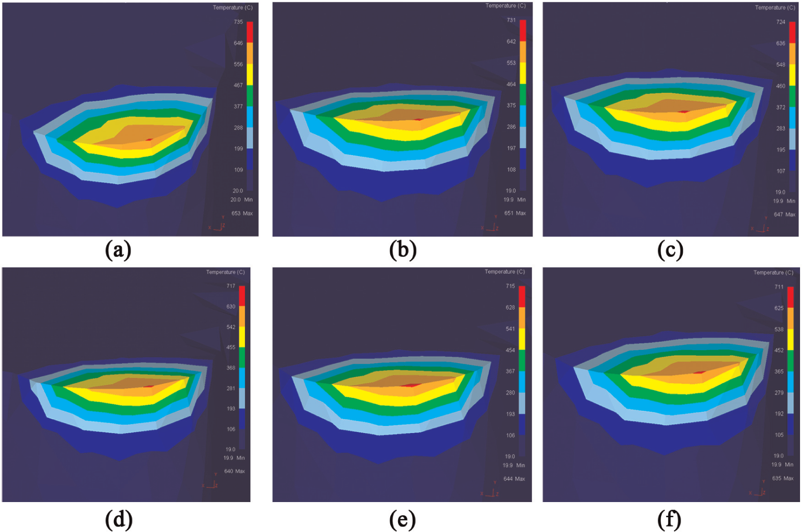
Predicted steady-state tool temperature distribution at the cutting speed of 104 m/min: (a) dry cutting, (b) refrigerated compressed air (−10 °C), (c) refrigerated compressed air (−30 °C), (d) refrigerated compressed air (−50 °C), (e) refrigerated compressed air (−100 °C), and (f) refrigerated compressed air (−140 °C).
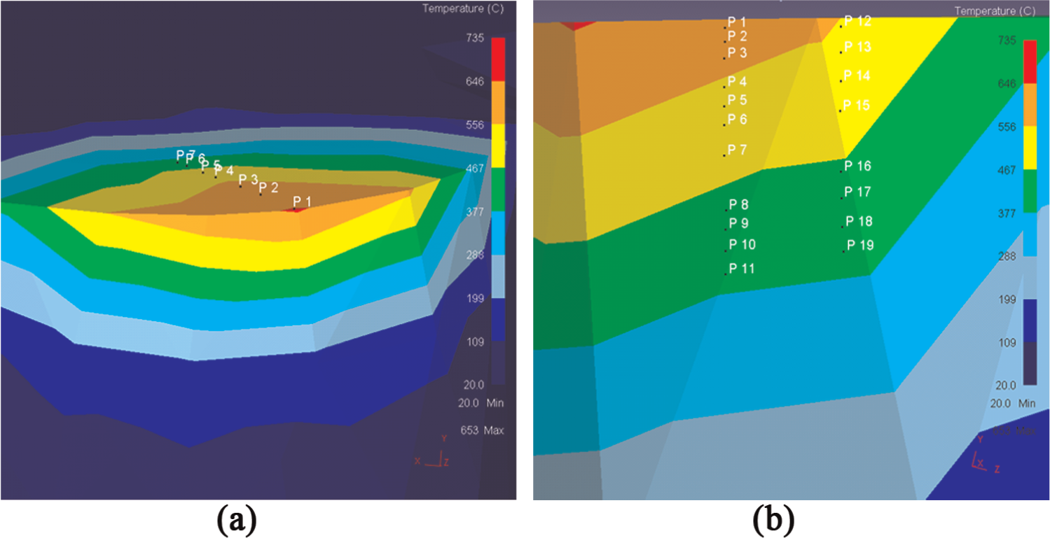
Some points defined on rake and flank faces for calculating the tool temperature: (a) rake face and (b) flank face.
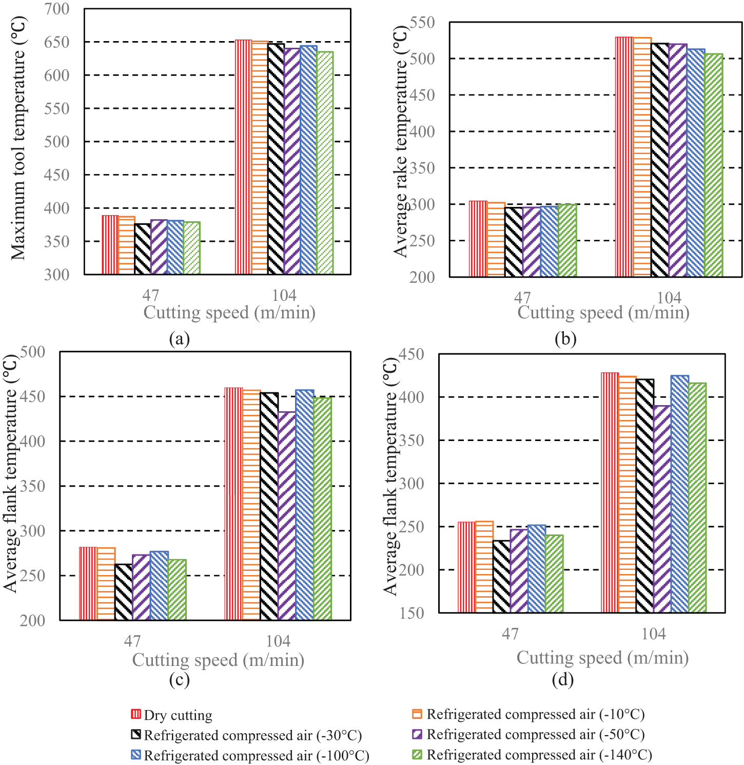
Comparison of tool temperature for dry cutting and refrigerated compressed air with different temperatures obtained from the simulation: (a) maximum tool temperature, (b) average rake temperature, (c) average flank temperature at position 1, and (d) average flank temperature at position 2.
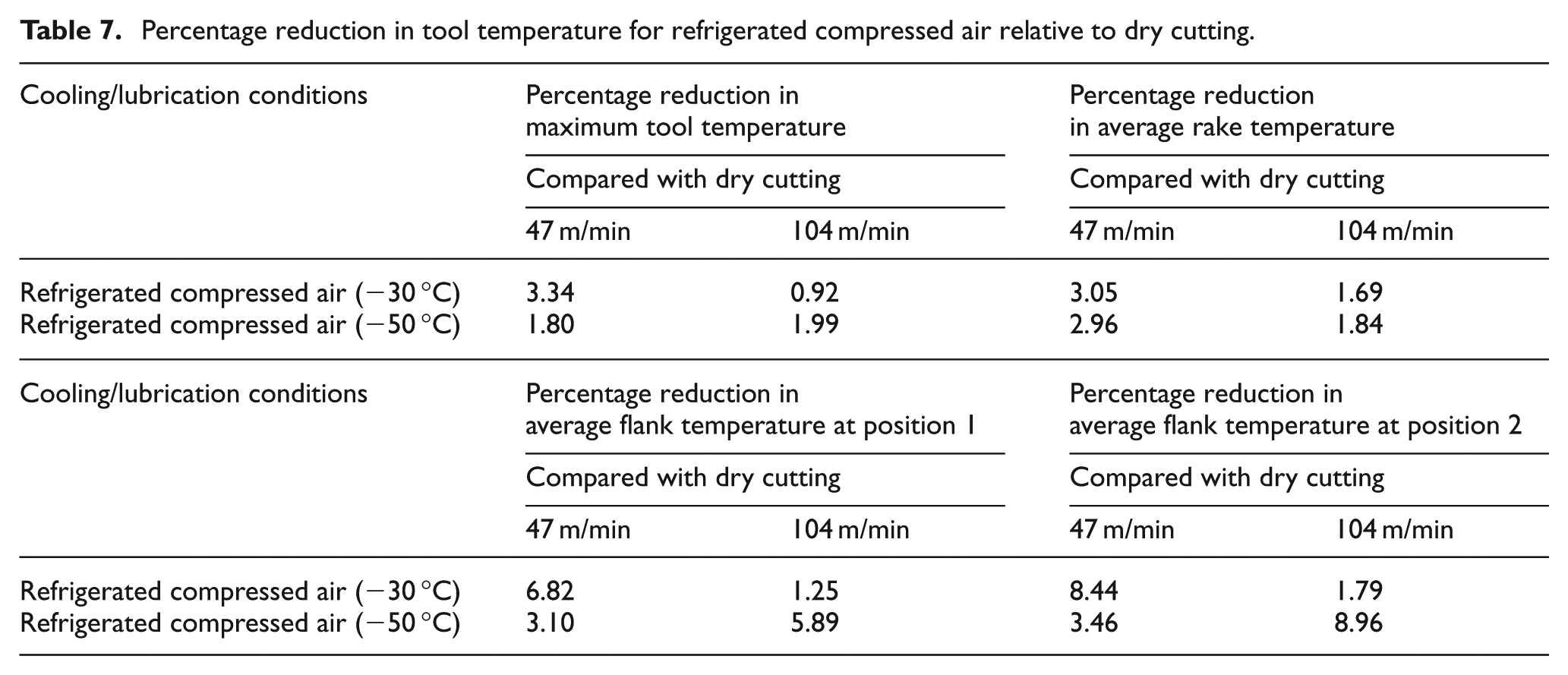
Figure 10 shows a comparison of tool temperature among dry cutting, refrigerated compressed air, and CMQL obtained from the simulation. It can be observed that there was an apparent reduction in tool temperature for CMQL as compared to dry cutting and refrigerated compressed air. The percentage reduction in tool temperature for refrigerated compressed air relative to dry cutting and that for CMQL relative to refrigerated compressed air are given in Tables 7 and 8, respectively. By comparing Table 7 with Table 8, it can be found that the percentage reduction in maximum tool temperature, average rake temperature, and average flank temperature resulting from the cryogenic cooling effect was generally bigger than that resulting from the lubrication effect provided by CMQL at the cutting speed of 47 m/min, while it was contrary at the high cutting speed (104 m/min). This indicates that the reduction in tool temperature with CMQL at the cutting speeds of 47 and 104 m/min was mainly attributed to the cryogenic cooling effect and lubrication effect provided by CMQL, respectively. In addition, a considerable reduction in tool temperature at both cutting speeds, caused by the improvement in lubrication effect provided by CMQL, was observed from Table 9.
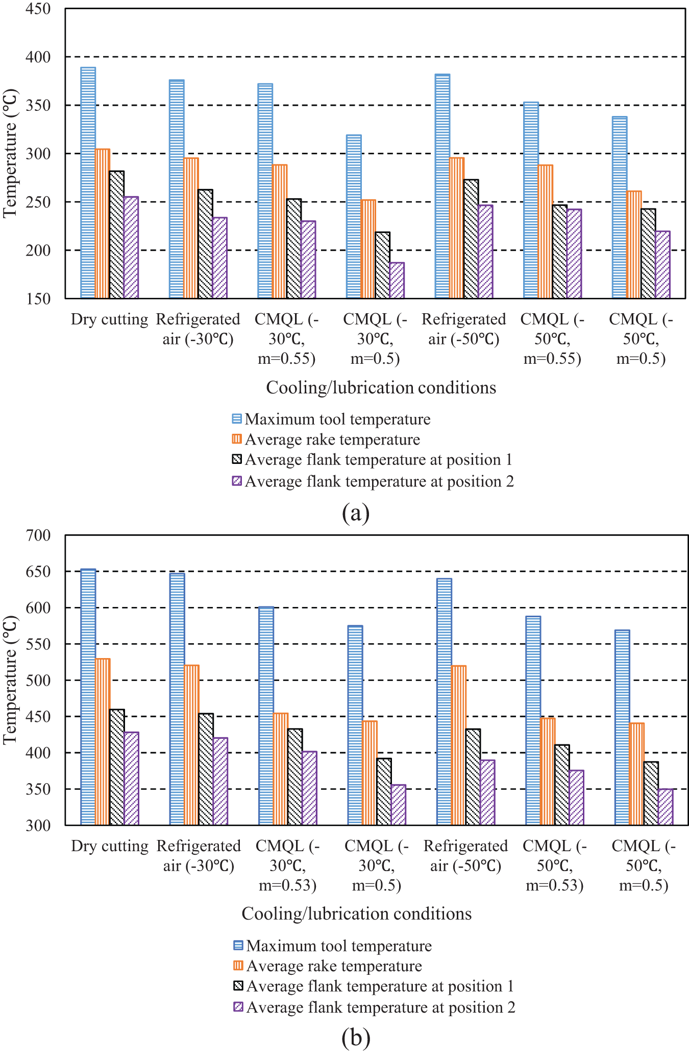
Comparison of tool temperature among dry cutting, refrigerated compressed air, and CMQL obtained from the simulation: (a) 47 m/min and (b) 104 m/min.
Percentage reduction in tool temperature for refrigerated compressed air relative to dry cutting.
Percentage reduction in tool temperature for CMQL relative to refrigerated compressed air.
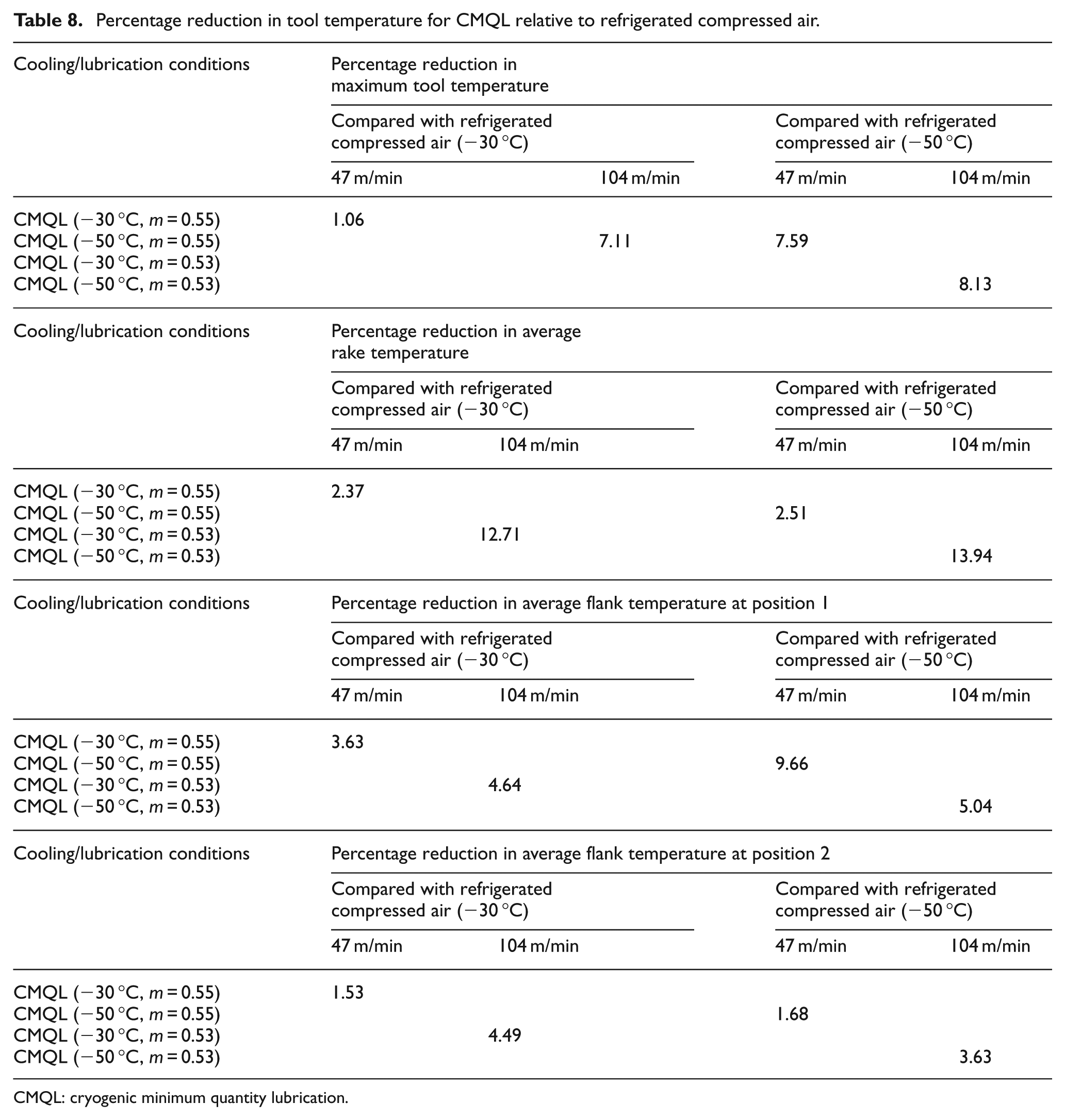
CMQL: cryogenic minimum quantity lubrication.
Percentage reduction in tool temperature resulting from improvement in lubrication effect provided by CMQL.
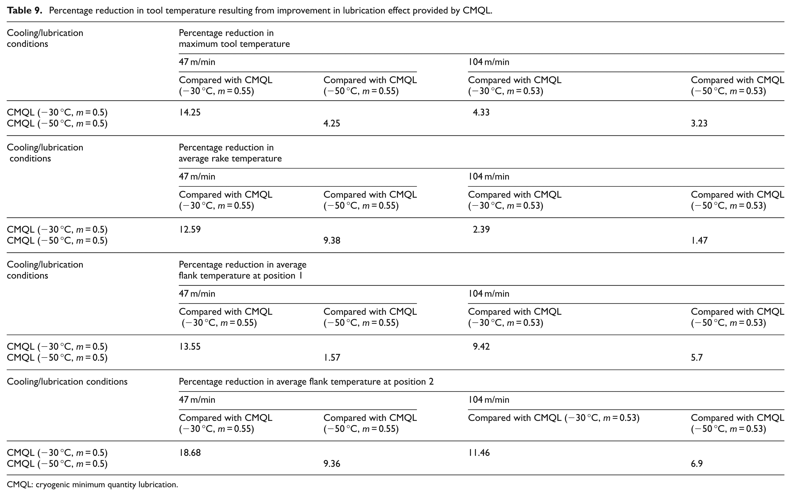
CMQL: cryogenic minimum quantity lubrication.
Simulation results illustrate that the reduction in cutting force and tool temperature at low and high cutting speeds depended strongly on the cryogenic cooling effect and lubrication effect provided by CMQL, respectively. Besides, the enhancement of lubrication effect provided by CMQL brought about a significant reduction in cutting force and tool temperature regardless of cutting speed. Thus, improving the lubrication effect of CMQL as far as possible will be the development direction for CMQL cutting of AISI H13 tool steel. As pointed out by Itoigawa et al., 34 in order to achieve a good cutting performance by MQL, two conditions are required: (1) an appropriate lubricant to form a strong boundary lubrication film and (2) a chilling effect to sustain strength of boundary lubrication film. When machining AISI H13 tool steel under CMQL condition, enhanced cooling effect by using refrigerated compressed air reduces the evaporation of lubricant and keeps the strength of boundary lubrication film, thus improving the lubrication performance. The proper selection of temperature of refrigerated compressed air is very important for CMQL cutting because it correlates with the lubrication effect of CMQL. It cannot be observed from simulation results that the lower the temperature of refrigerated compressed air, the lower the cutting force and tool temperature (see Figures 5 and 9). In addition, refrigerated compressed air with extremely low temperature makes the lubricant frozen. The suitable temperature range of refrigerated compressed air for CMQL cutting should be at −30 °C to −50 °C (see Figures 5 and 9).
In this work, shear friction factor was set at 0.55 and 0.53 when simulating CMQL (−30 °C or −50 °C) cutting of AISI H13 tool steel at the cutting speeds of 47 and 104 m/min, respectively. However, it should be noted that the used value of shear friction factor was achieved experimentally under CMQL (−20 °C) condition due to the limitation of refrigerated compressed air generator currently used. Figures 5 and 9 clearly show that −30 °C or −50 °C was the optimum temperature of refrigerated compressed air that led to the minimum cutting force and tool temperature. Thus, it can be reasonably anticipated that better lubrication effect or smaller shear friction factor can be obtained when the temperature of CMQL is from −20 °C to −30 °C or −50 °C. With a decrease in shear friction factor, the lubrication effect provided by CMQL becomes a more predominant mechanism for reduction in cutting force and tool temperature at both cutting speeds (see Figures 6 and 10).
Conclusion
In this article, a thermo-mechanical coupled 3D FE model has been developed to simulate the CMQL cutting process of AISI H13 tool steel. The role of cooling/lubrication effect in CMQL cutting was analyzed by FEM cutting simulation. Due to the lack of refrigerated compressed air generator with wide operating temperature range, no experimental work was carried out to verify this model, but the trends revealed by the simulation should provide useful insights into the CMQL cutting process of AISI H13 tool steel. Based on the results obtained from the cutting simulation, the following conclusions can be drawn:
Cutting forces and tool temperature did not decrease continuously with the decrease in the temperature of refrigerated compressed air. There existed an optimal temperature of refrigerated compressed air that provided the minimum cutting forces and tool temperature. The optimum refrigerated compressed air temperature for 47 and 104 m/min was −30 °C and −50 °C, respectively.
The reduction in cutting force and tool temperature at low and high cutting speeds depended strongly on the cryogenic cooling effect and lubrication effect provided by CMQL, respectively. Besides, the improvement of lubrication effect provided by CMQL led to a significant reduction in cutting force and tool temperature irrespective of cutting speed.
Improving the lubrication effect of CMQL, by means of optimizing oil quantity and developing high-performance lubricating medium and effective supplying method of oil mist for CMQL, will be the development direction for CMQL cutting of AISI H13 tool steel.
The sensitivity analysis of cutting force and cutting temperature to the heat transfer coefficient of CMQL, depth of cut, and cutting speed should be further performed by detailed FE investigations to optimize the CMQL cutting process of AISI H13 tool steel.
Footnotes
Declaration of conflicting interests
The author declares that there is no conflict of interest.
Funding
This research was financially supported by the National Natural Science Foundation of China under contract no. 51205177, Natural Science Foundation of Jiangsu Province under contract no. BK2012277, Natural Science Program for Basic Research of Jiangsu Province under contract no. 08KJB460002, Qing Lan Project, and Research Fund of DML-HYIT (HGDML-0901).