
Abstract
This article proposes a volumetric error generalized model and a distributed error compensation technique for multi-machine tools. A detailed generalized kinematic model for three- and five-axis machine tools is built. It can be applied to 4 types of three-axis machine tools and 12 types of five-axis machine tools. By simply inputting the translational and rotary type numbers of the specific machine tool, the final kinematic model can be obtained without further human interventions. A new compensation technique based on an Ethernet distributed numerical control system is proposed. Ethernet distributed numerical control software integrated with the generalized kinematic model is developed for machine tools with Fanuc and Siemens systems. Based on the Ethernet distributed numerical control system, the real-time volumetric errors of multi-machine tools are simultaneously compensated for. The proposed generalized kinematic model and Ethernet distributed numerical control systems are experimentally verified on three machine tools, whose volumetric errors are significantly reduced after compensation.
Keywords
Introduction
The demand for the high volumetric accuracy of machine tools is increasing. The ultimate performance of volumetric errors on machine tools is the position and orientation deviations of the tool relative to the workpiece. Building a volumetric error model of the machine tool is crucial to obtain and compensate for the volumetric error map of the working space. The homogeneous transfer matrix (HTM) method is a widely used mathematical strategy to build the volumetric error model.
Various volumetric error models of machine tools have been built according to their specific axes configurations. In the research of Hsu and Wang, 1 a RRTTT 2 five-axis machine tool was used to construct a kinematic model, and a compensation method was proposed, so that the rotary axes are first compensated for, followed by the linear axes. Khan and Chen 3 designed a recursive compensation methodology to compensate for all geometric errors in the volumetric workspace of RTTTR five-axis machine tools. Zhu et al. 4 proposed an integrated geometric error modeling, identification and compensation method for a TTTRR five-axis machine tool.
However, these volumetric error models are only applicable to machine tools with specific structures. Therefore, these models lack versatility. Sakamoto and Inasaki 5 indicated that up to 162 types of five-axis machine tools could possibly be constructed. Tsutsumi and Saito 6 listed 24 types of five-axis machine tools that have been manufactured in Japan. Many researchers have developed generalized kinematic models of five-axis machine tools. Aguado et al. 7 developed a general verification method of volumetric errors based on a laser tracker. Soons et al. 8 presented a generalized error model for multi-axis machines of arbitrary configuration, including three- and five-axis machine tools. With a heaviside step function, Tutunea-Fatan and Feng 9 proposed a generic kinematic model that was applicable to three main types of five-axis machine tools. Many other researchers have built generalized forward and inverse kinematic models to generate the tool paths and cutting points in the post-processor. Bohez 10 proposed a general approach to compensate for the systematic errors based on the closed-loop volumetric error relations. Peng et al. 11 used total differential methods to develop a universal kinematics model and post-processing algorithm of multi-axis machine tools. She and Chang 12 built a generalized kinematics model of common five-axis machine tools by combining two rotational degrees of freedom on the fixture table and two rotational degrees of freedom on the spindle. Yang and Altintas 13 presented a generalized kinematic model for five-axis machine tools based on screw theory; the model allowed automatic configurations, including nonorthogonal configurations. Moon and Kota 14 also used screw theory to build generalized kinematic models of reconfigurable machine tools.
Nevertheless, these generalized models were not refined to the specific form of homogeneous matrices. This article will present a detailed generalized modeling method for multi-axis machine tools in section “Generalized kinematic models for three- and five-axis machine tools.” In this generalized model, the final kinematic model can be determined without further human interventions by simply inputting the corresponding translational and rotary type numbers.
The volumetric error model can be used to obtain the errors of the tool tip relative to the workpiece. In the previously presented studies,10–14 volumetric errors are commonly compensated for by generating new G-codes with the post-processor. Zhang et al. 15 introduced the external machine zero point shift (EMZPS) method for real-time error compensation in machine tools with Fanuc computer numerical control (CNC) systems. Cui et al. 16 proposed a novel error compensation technique for a Siemens 840D CNC system using a differential resolve function method. However, in these compensation methods, each machine tool should usually be allocated its own compensator and software. The efficiency will be improved and the cost will be cut down if multi-machine tools can be compensated together by a controller. To simultaneously compensate for the volumetric error of multi-machine tools, an Ethernet distributed numerical control (EDNC) technique is proposed for both Fanuc and Siemens CNC systems in section “EDNC system.” EDNC software that is integrated with the generalized kinematic model is developed and presented. The rest of this article is organized as follows: section “Experiments and results” contains various experimental verifications, and conclusions are drawn in section “Conclusions and future work.”
Generalized kinematic models for three- and five-axis machine tools
Prior to building the generalized kinematic model, several rules are illustrated as follows. All coordinate systems used are right-handed Cartesian coordinate systems. The linear errors are positive when they are in the same direction of the coordinate axes, while the angular deviations are positive when they meet the right-hand helix. The definition of the positive direction for angular deviations is depicted in Figure 1. In this research, the kinematic chain originates from the work-piece to the tool tip, and all squareness errors are measured in the same benchmark of the X-axis. All errors in the model are positive by default unless the direction of the measured error is opposite to the positive direction.
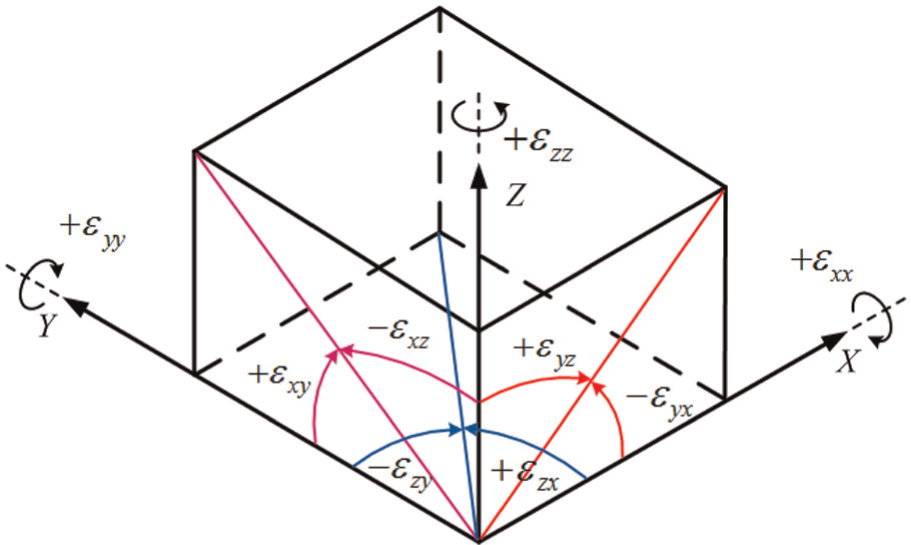
Definition of positive direction for angular deviations.
Generalized kinematic model of three-axis machine tools
Figure 2 presents four types of three-axis machine tools. These machine tools can be categorized according to the movement of the workpiece and the cutting tool as FXYZ, XFYZ, XYFZ and XYZF. 7 The parameter F represents the fixed part of the machine tool. The letters to the right of F represent the axes that move with the cutting tool, and the letters to the left of F represent the axes that move with the workpiece. 7 In this research, the machine coordinate system (MCS) of the machine tool is always fixed, and therefore, it is set as F.
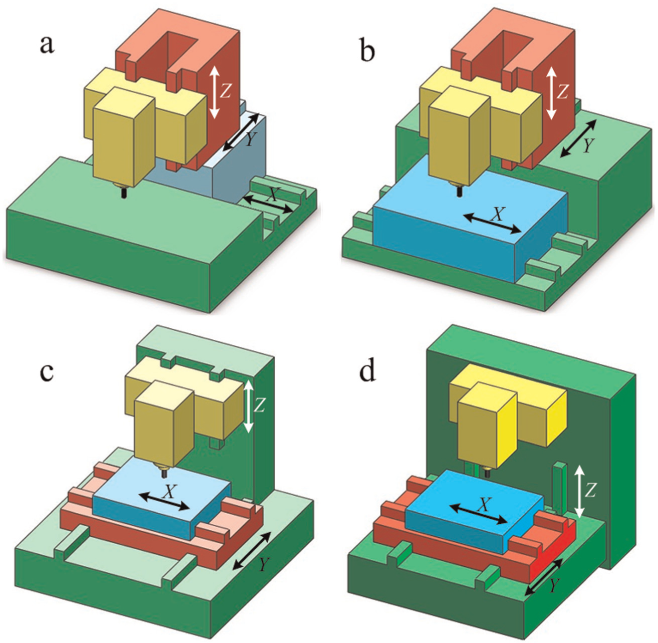
Four types of three-axis machining tools: (a) FXYZ, (b) XFYZ, (c) XYFZ and (d) XYZF.
For the FXYZ-type machine tool, which is depicted in Figure 2(a), the kinematic chain from the workpiece coordinate system (WCS) to the tool coordinate system (TCS) can be expressed by equation (1)

where
In ideal situations, where there are no errors, the transfer matrix
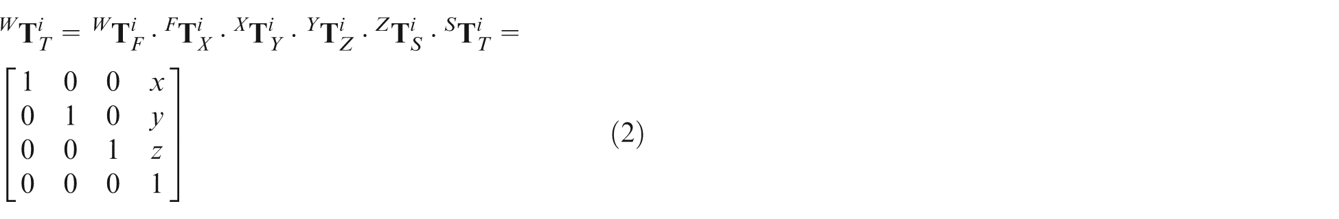
where x, y and z are nominal displacements of feed axes.
However, in practical situations, there are 21 well-known geometric errors in three-axis machine tools. Consequently, the transfer matrices from F to X, X to Y and Y to Z are, respectively, described by equations (22)–(24) in Appendix 2. The transfer matrix

The relationship between

Substituting equations (22)–(24) into equation (4), the error motion matrix
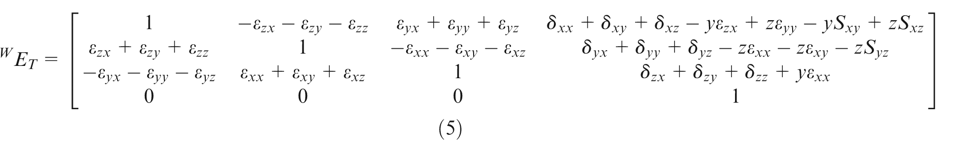
The positional part of the error motion matrix is expressed in equation (6)
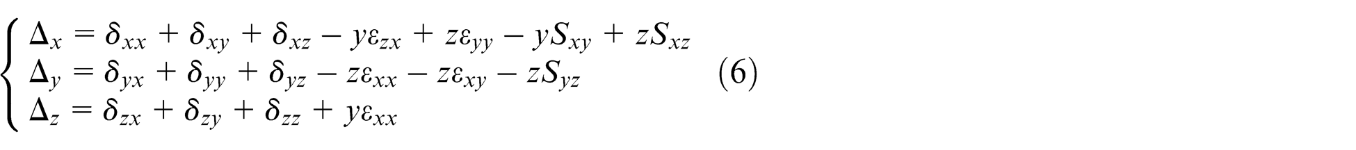
Δx, Δy and Δz are the error displacements of the machine tool in the workspace. They are position dependent and can be used to compensate the volumetric errors by adding movements to the feed axes in the reverse directions. In order to determine the values of Δx, Δy and Δz, there are two necessary steps. One is to measure and model the component errors and the other is to real-time record the actual positions of the feed axes.
According to the structure of four types of three-axis machine tools which are depicted in Figure 2, their kinematic chains are expressed as follows
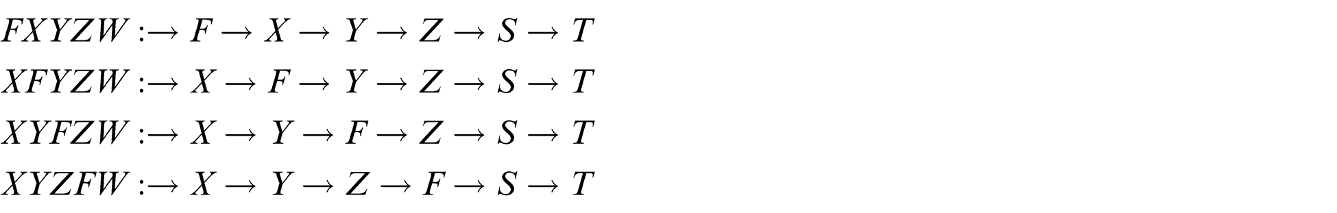
The transformation direction of the HTMs on the right-hand side of F is positive, while the direction of the HTMs on the left-hand side is negative. A singular function expressed in equation (7) is added to the HTMs to obtain a generalized kinematic model. The singular function can automatically determine whether the transformation direction is positive or negative according to the corresponding machine tool type 17

where
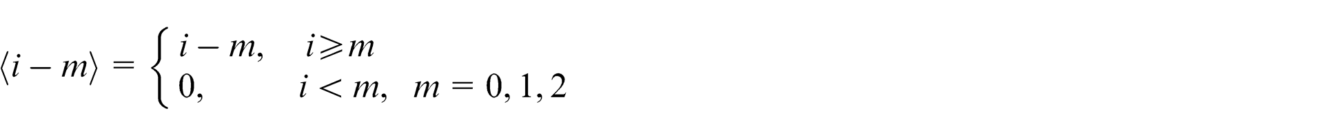
especially,
Using the singular function, equations (22)–(24) can be rewritten as equations (8)–(10), which are the generalized transfer matrices of
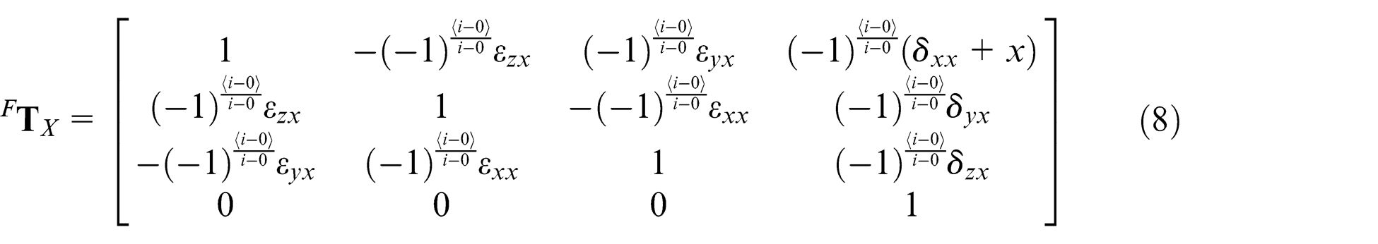
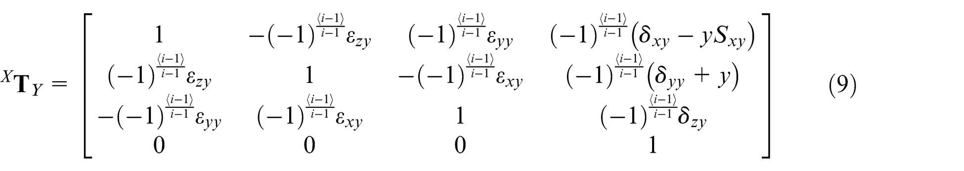
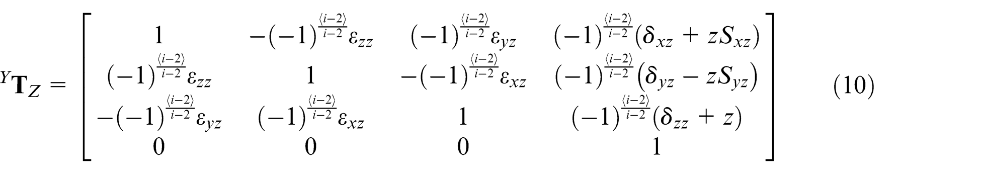
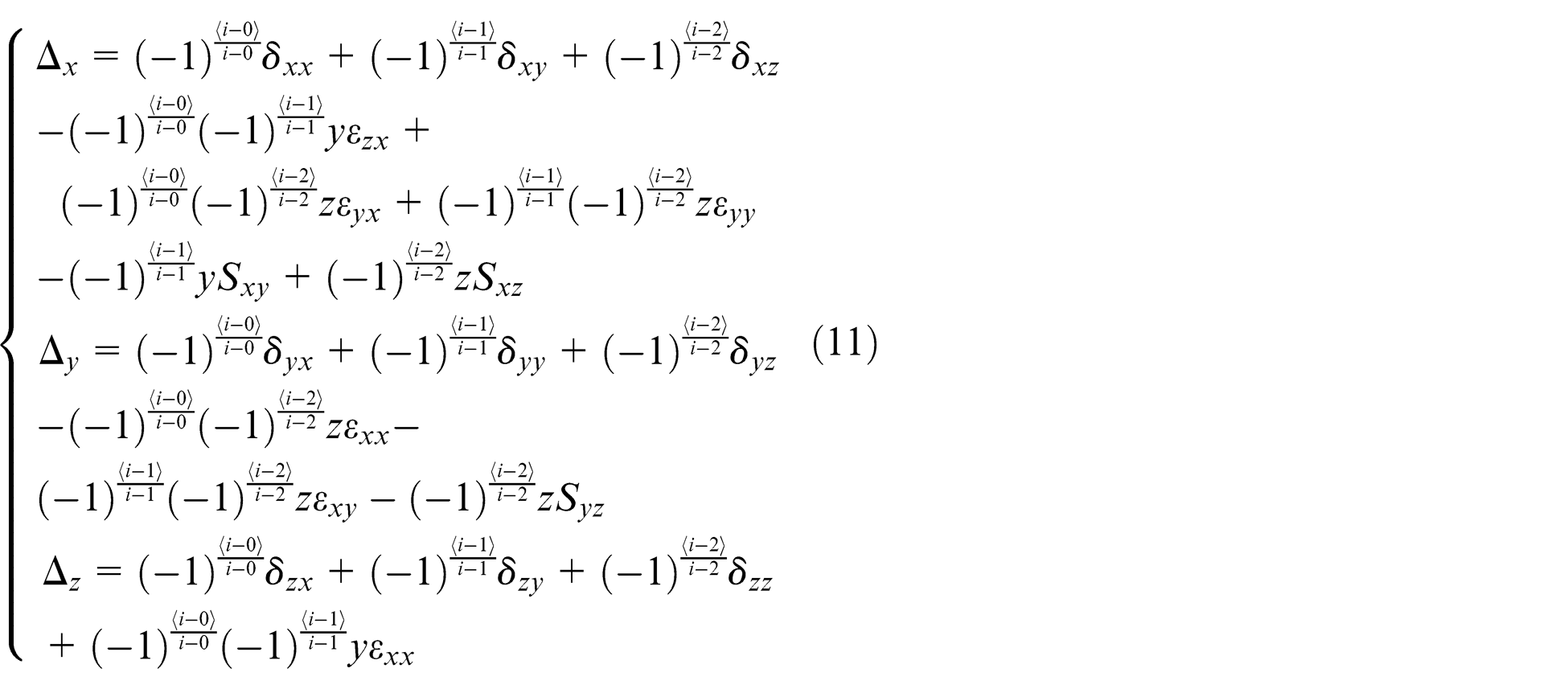
Equation (11) presents the position error components of the generalized kinematic model. Because of the limited space, the orientation error components are not listed. Only the corresponding translational type number, i, needs to be input to obtain the final kinematic model. Based on equation (11), the positional displacements Δx, Δy and Δz in the whole workspace are determined. The volumetric errors can be compensated by adding reversal movements to the feed axes
Generalized kinematic model of five-axis machine tools
Five-axis machine tools play a significant role in precision engineering. They provide greater productivity, better flexibility and less fixture time than three-axis machine tools. The structures of five-axis machine tools vary depending on the needs of industrial applications. However, their configurations simply consist of three translational axes and two rotary axes in different combinations.
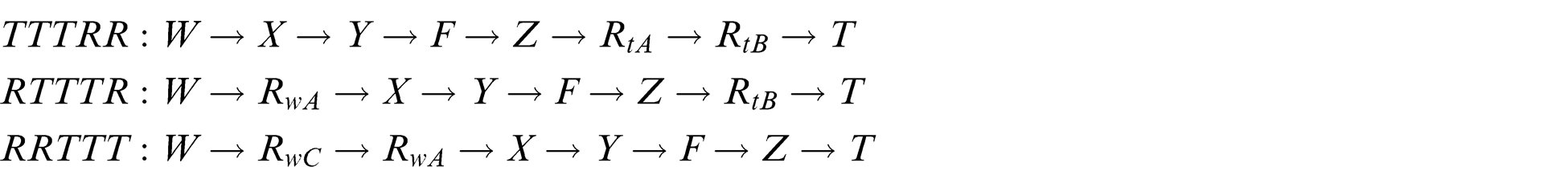
Five-axis machine tools can be grouped into three classes: 5 (1) spindle-tilting-type tools with both rotary axes on the table (Figure 3(a)), (2) table-tilting-type tools with both rotary axes on the spindle (Figure 3(b)) and (3) table/spindle-tilting-type tools with one rotary axis each on the table and spindle (Figure 3(c)). These three types of five-axis machine tools are represented by TTTRR, RRTTT and RTTTR. 2 The parameter R indicates the rotary axis and T indicates the translational axis.
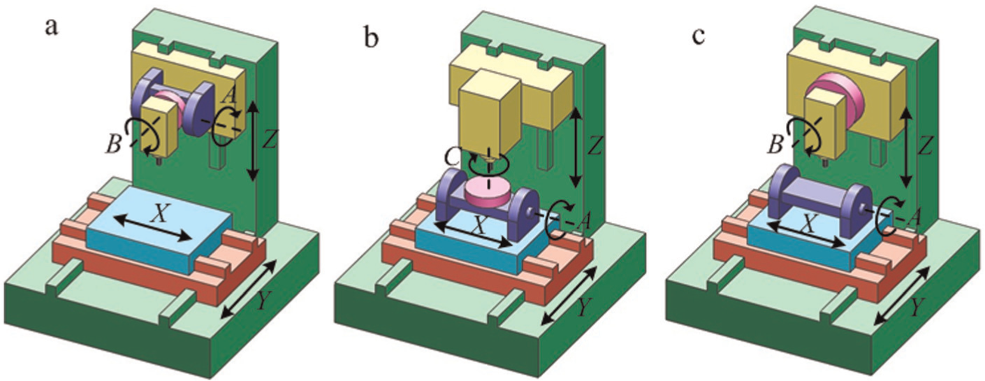
Three types of five-axis machine tools: (a) spindle-tilting, (b) table-tilting and (c) table/spindle-tilting.
The two rotary axes are either on the table or on the spindle. Therefore, we can effectively build a generalized model that is suitable for all rotary configurations by configuring two rotary axes on each side. Each rotary axis has three forms, namely, A, B and C. In this research, only AB, A′C′ and BA′ are considered because they are the most common five-axis types. Symbols A, B and C represent the rotary axes at the spindle side, while A′, B′ and C′ represent those at the table side. As shown in Figure 4, the generalized model of five-axis machine tools was built by adding four rotary axes to the three translational axes.
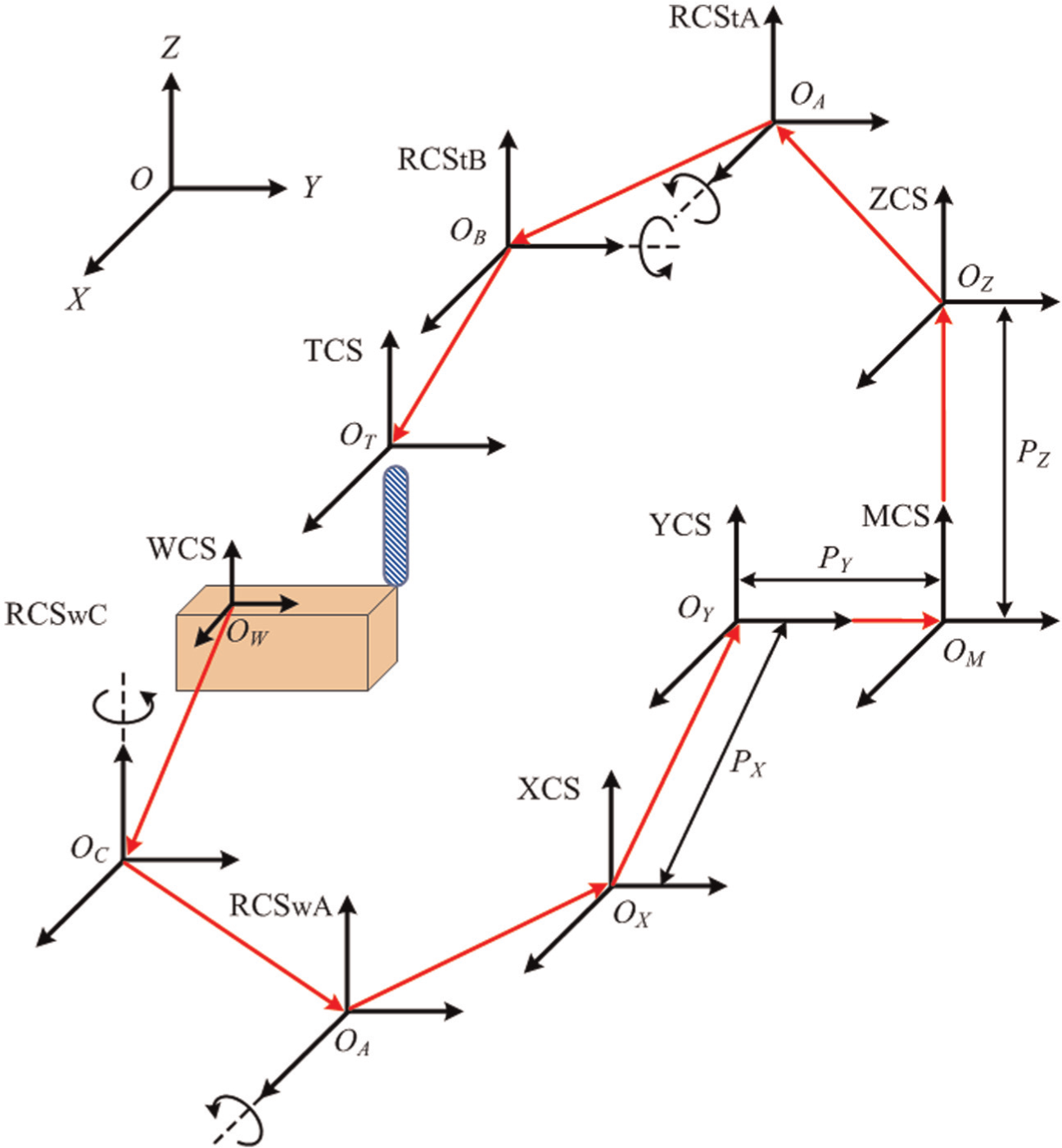
Coordinate systems for generalized five-axis machine tools.
The kinematic chain of the generalized model from the WCS to the TCS is expressed as follows
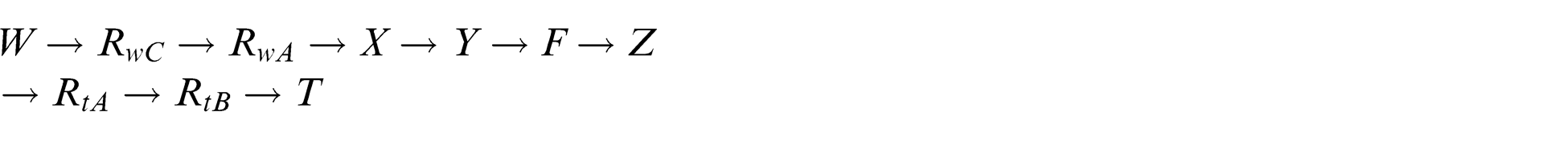
where RwC and RwA are rotary axes C and A on the worktable, while RtA and RtB are rotary axes A and B on the spindle.
The kinematic chains of the five-axis machine tools depicted in Figure 3 can be detailed as follows
Similar to the generalized modeling methodology for three-axis machine tools described in section “Generalized kinematic model of three-axis machine tools,” a new singular function is introduced as follows

where
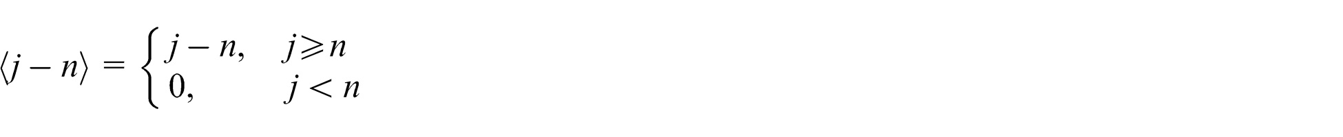
especially,
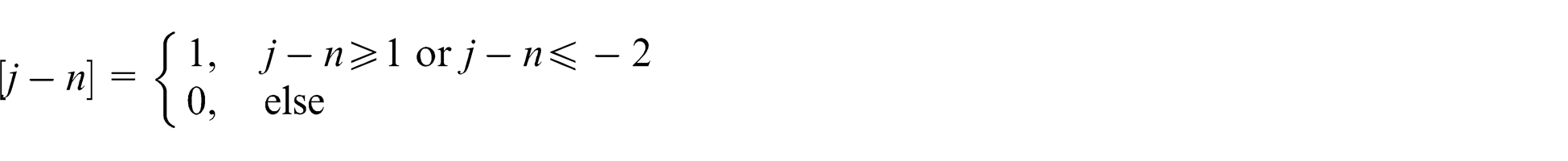
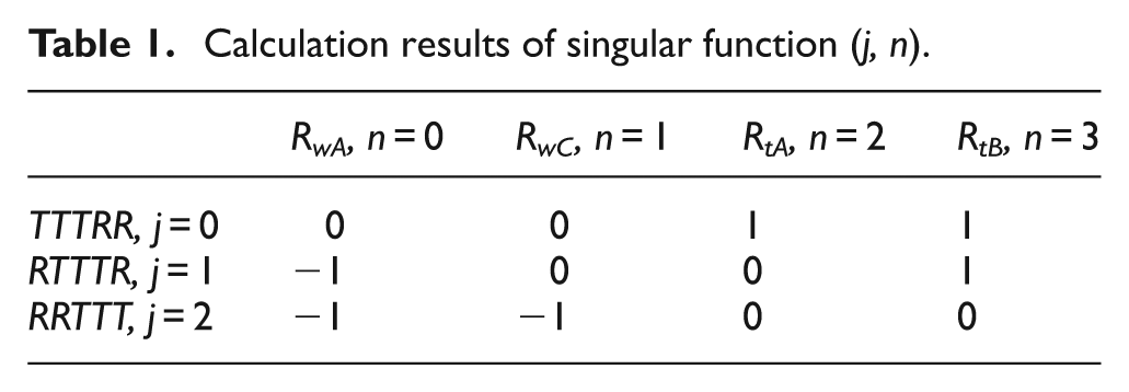
The parameters j = 0, 1, 2, respectively, represent the three types of five-axis machine tools, TTTRR, RTTTR and RRTTT. The parameters n = 0, 1, 2, 3, respectively, represents the rotary matrices of
Table 1 lists all of the calculation results of singular function (j, n) under different combinations. For example, (0, 0) = 0, (0, 2) = 1 and (2, 1) = −1. Only three outputs exist for (j, n), namely, 0, 1 and −1. The singular function acts on HTMs as shown in equation (13)

Calculation results of singular function (j, n).
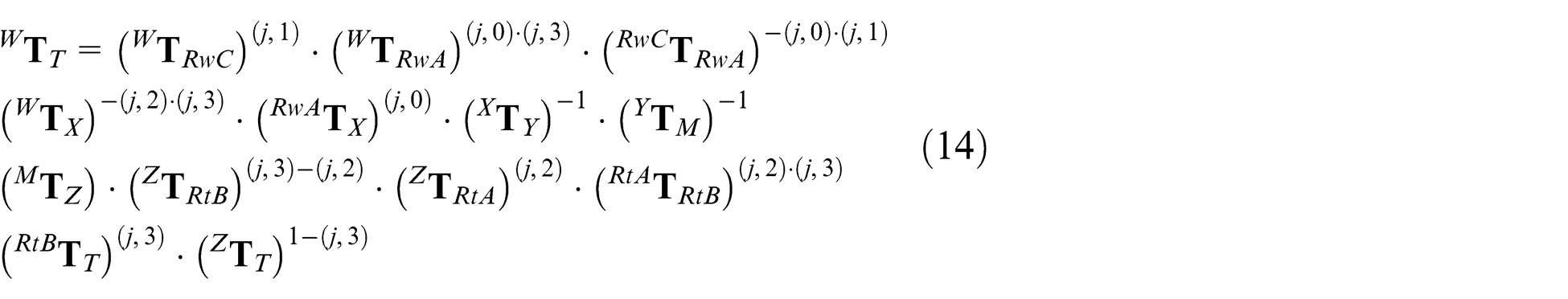
The generalized kinematic model is expressed with the singular function in equation (14), which is fit for all of the three types of five-axis machine tools as depicted in Figure 3. Only the corresponding rotary type number, j, needs to be input to obtain the final expanded kinematic model
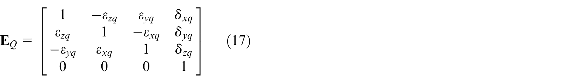
Considering the geometric errors of each axis, each matrix in equation (14) should be expanded as equations (15) and (16)


where
The inverse of a matrix often needs to be calculated in the generalized kinematic model expressed in equation (14); equations (18) and (19) describe an effective and convenient method to obtain the inverse form of a 4 × 4 HTM
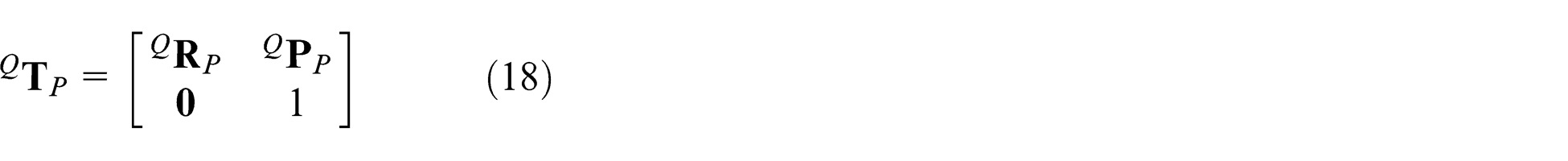
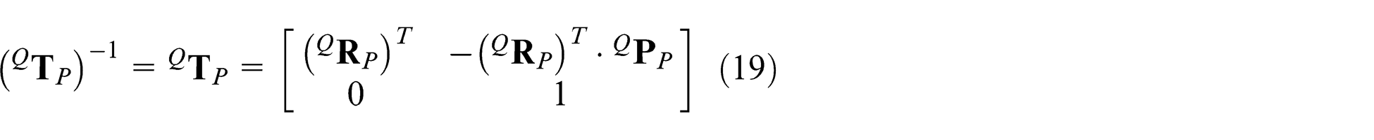
where
However, the generalized kinematic model expressed in equation (14) is only suitable for three types of five-axis machine tools with the translational configuration X → Y → F → Z. Based on section “Generalized kinematic model of three-axis machine tools,” a generalized kinematic model for four types of three-axis machine tools was obtained. This model can be naturally integrated into the five-axis generalized model. The final generalized model of five-axis machine tools is obtained in equation (20) by adding the variable i introduced in section “Generalized kinematic model of three-axis machine tools” to equation (14)
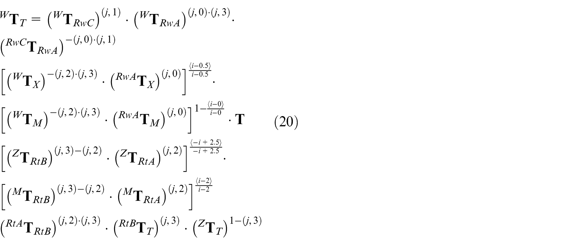
where
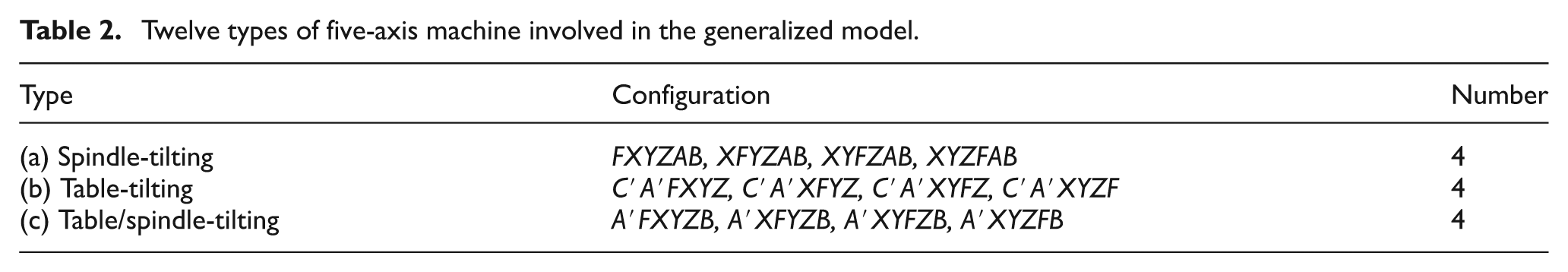
The generalized kinematic model expressed by equation (20) can represent 12 types of five-axis machine tools, which are combinations of three rotary configurations and four translational configurations. Table 2 lists the 12 types of five-axis machine tools represented by the generalized model.
Twelve types of five-axis machine involved in the generalized model.
For a machine tool with specific configurations, only the corresponding i and j are needed to obtain the final expanded kinematic model without further human interventions. The positional error motions Δx, Δy and Δz can be obtained in equation (21)
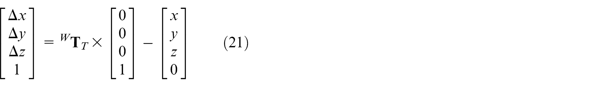
Similar to equation (6), after all the component errors are determined, the error motions Δx, Δy and Δz can be compensated by adding the reverse movements to the three feed axes. The generalized model of three- and five-axis machine tools can effectively identify the error motions of multi-machine tools. However, to simultaneously realize the error compensation of multi-machine tools, an effective compensation technique is developed, which will be described in the next section.
EDNC system
Once the kinematic model is generated, the volumetric error map of the entire workspace can be obtained after the measurement of all component errors. Effective compensation methods are needed to compensate for the volumetric error. Recently, researchers have applied Ethernet technology to implement the communication of CNC systems.18,19 The Ethernet technology enhances the real-time communication between a control center and multi-machine tools.
In the conventional compensation method, each machine tool should usually be allocated to its own compensator and software. An EDNC technique is proposed for both the Fanuc and Siemens CNC systems to simultaneously compensate for the volumetric error of multi-machine tools. Integrated with the generalized kinematic model described in section “Generalized kinematic models for three- and five-axis machine tools,” the EDNC system can not only cut down the cost but also compensate for the volumetric error and monitor the condition of multi-machine tools. The following will briefly present the schematic of EDNC and the development of software.
Figure 5 shows the connection schematic diagram of various hardware modules involved in the EDNC system. CNC systems of multi-machine tools are all connected to a router via Personal Computer Memory Card International Association (PCMCIA) cards or network cables. Multi-machine tools communicate with the control center via the Ethernet. By matching each machine tool’s unique Internet protocol (IP) address, the control center can discern its identity and send the corresponding compensation values to realize real-time error compensation.
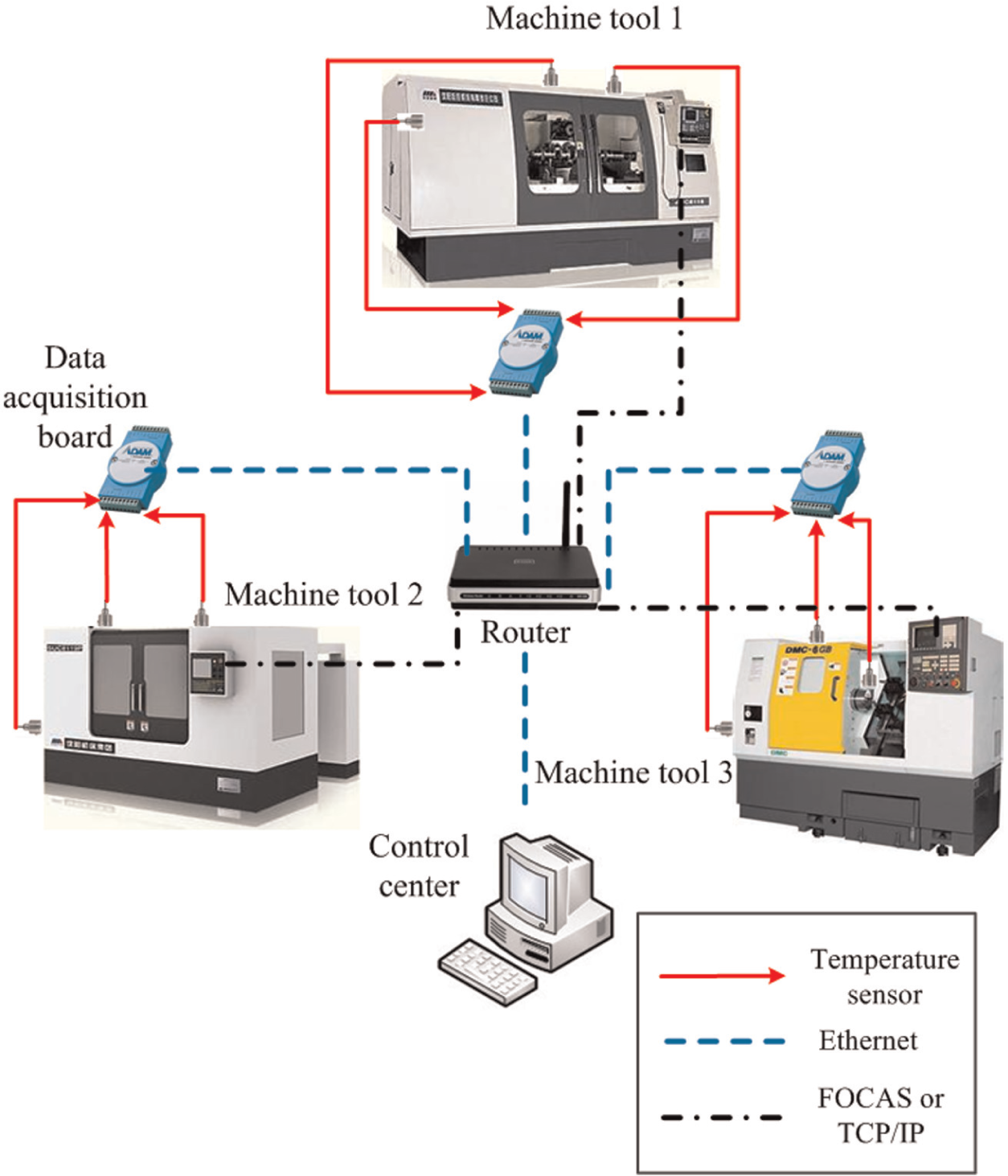
Schematic diagram of EDNC.
Figure 6 presents the EDNC flowcharts for Fanuc and Siemens machine tools. Fanuc CNC systems provide users with a protocol for communication, namely, the Fanuc Open CNC API Specifications (FOCAS) protocol. Based on FOCAS, the communication between a control center and multi-machine tools is achieved. The temperature data can be collected by the thermistor PT100 in association with a data acquisition board featured by Ethernet data transmission function. Based on the EMZPS function, the error can be compensated for by simply writing compensation values into the corresponding R-address.
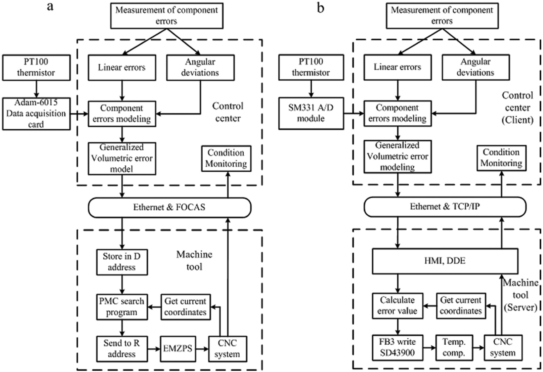
Error compensation flowchart of EDNC: (a) Fanuc system and (b) Siemens system.
Different from Fanuc, the Siemens CNC system contains a personal computer unit that runs on the Windows operating system. Thus, it supports the function of the dynamic data exchange (DDE), which helps Windows to read and write the CNC variables. Instead of FOCAS, the connection between multi-machine tools and the control center is based on the transmission control protocol (TCP)/IP because the Siemens is a computer that runs on Windows. The Siemens system can directly connect the temperature sensors via its SM331 analog-to-digital (A/D) module. For a Siemens machine tool, the error compensation can be realized by writing the compensation values into the setting-data 43900 after the machine-data 32750 is set to 1. Here, the setting-data and machine-data are two different data types in the Siemens CNC system.
In the EDNC system, one control center simultaneously communicates with multiple machine tools. To ensure the real-time compensation of each machine tool, the control center periodically sends each machine tool its specific error map, which will be stored in the machine tool’s memory. Each machine tool can read its current machine coordinates by a programmable logic controller (PLC) and select the corresponding compensation values.
Software for the error compensation integrated with the generalized kinematic model was developed. As shown in Figure 7, the control center can connect all machine tools in the EDNC system after searching the local network. By confirming the translational and rotary types of the corresponding machine tool, the specific kinematic model will be generated from the generalized model. The final volumetric error model of the corresponding machine tool is obtained after inputting the models of component errors in another form, presented in Figure 8.
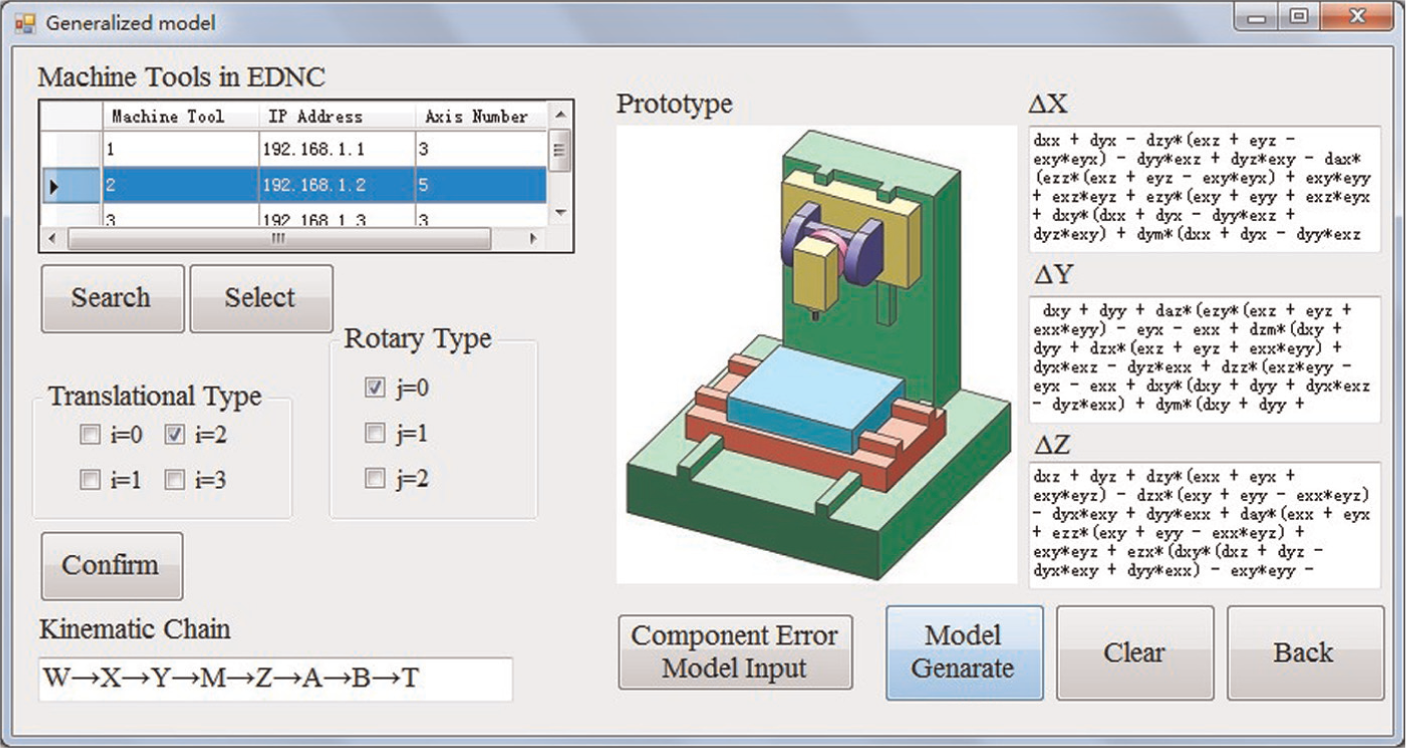
Generation of generalized model.
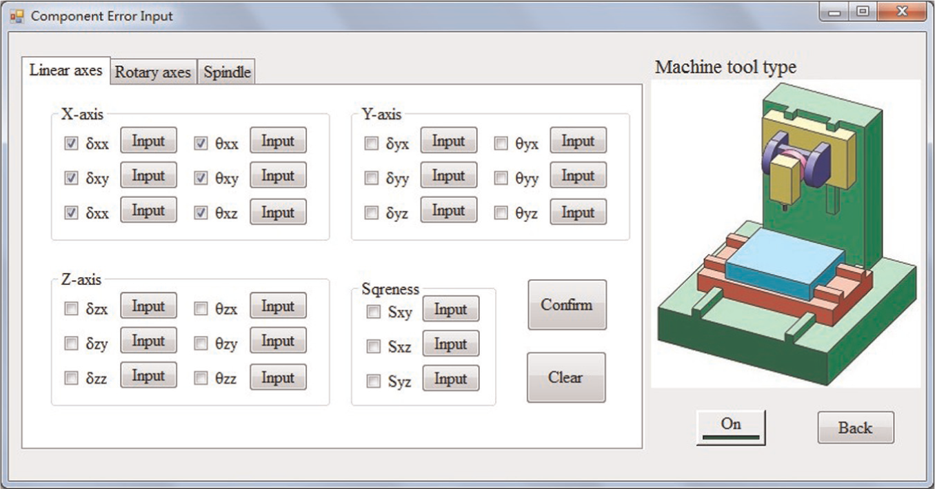
Component error models input.
Experiments and results
Experiments were simultaneously conducted on one 5-axis and two 3-axis machine tools with Fanuc CNC systems to verify the generalized model and EDNC systems. Experiments on multi-machine tools with Siemens CNC systems were also conducted, but they are not presented here due to limited space. The kinematic models were generated from the generalized model presented in section “Generalized kinematic models for three- and five-axis machine tools.”
Three-axis machine tools have 21 well-known component errors, while it rises to 39 when it comes to five-axis machine tools. 20 During the implementation, the volumetric error map was formed using the errors of three translational axes, while the errors of the rotary axes were not considered because of the difficulties in the measurement. Researchers21,22 proposed various modeling and measurement methods for component errors of machine tools. In this research, all component errors, such as positioning errors and straightness errors, of the three machine tools were measured and modeled as polynomials using the least squares method. Figure 9 shows the measurement process of component errors in a three-axis machine tool with a laser interferometer.
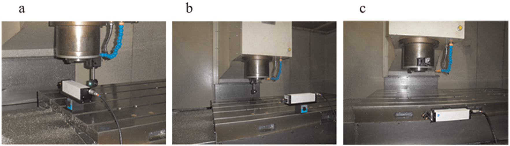
Measurement process of component errors in a three-axis machine tool: (a) X-axis error measurement, (b) Y-axis error measurement and (c) Z-axis error measurement.
The two 3-axis machines in the experiment were structured as depicted in Figure 2(b) and (c). The strokes of them are 800 × 650 × 500 and 1000 × 800 × 600. The kinematic models were obtained by inputting the translational type i = 1, 2 into equation (9). Another verification test was conducted on a five-axis machine tool, whose structure is depicted in Figure 3(b). It has a workspace of 800 × 600 × 600. The parameters i = 2 and j = 2 were substituted into equation (15) to establish the kinematic model. The rotary axes remained stationary during the experiment, and their error matrices were set as identity matrices. The volumetric errors of these three machine tools were simultaneously compensated for using the EDNC system. Figure 10 shows the error compensation process of a three-axis machine tool based on the EDNC system. One side of the PCMCIA card is connected to the Fanuc CNC system, and the other side is connected to a router. The control center sends the corresponding compensation values to the machine tool via Ethernet after identifying its IP address.
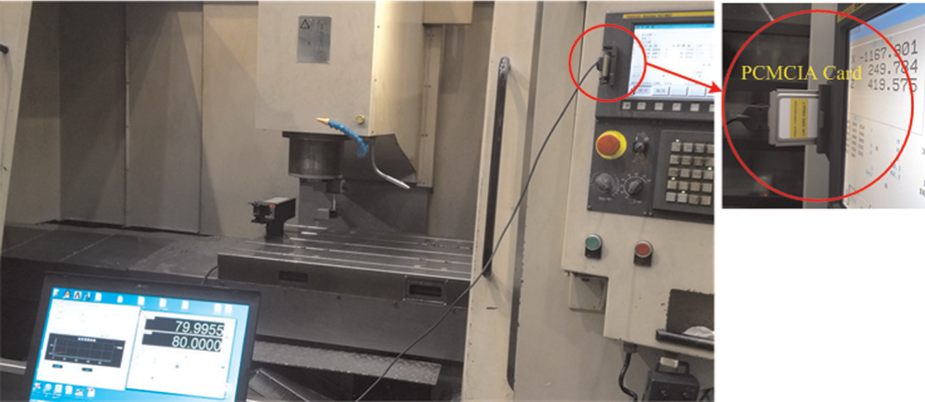
Error compensation process based on EDNC system.
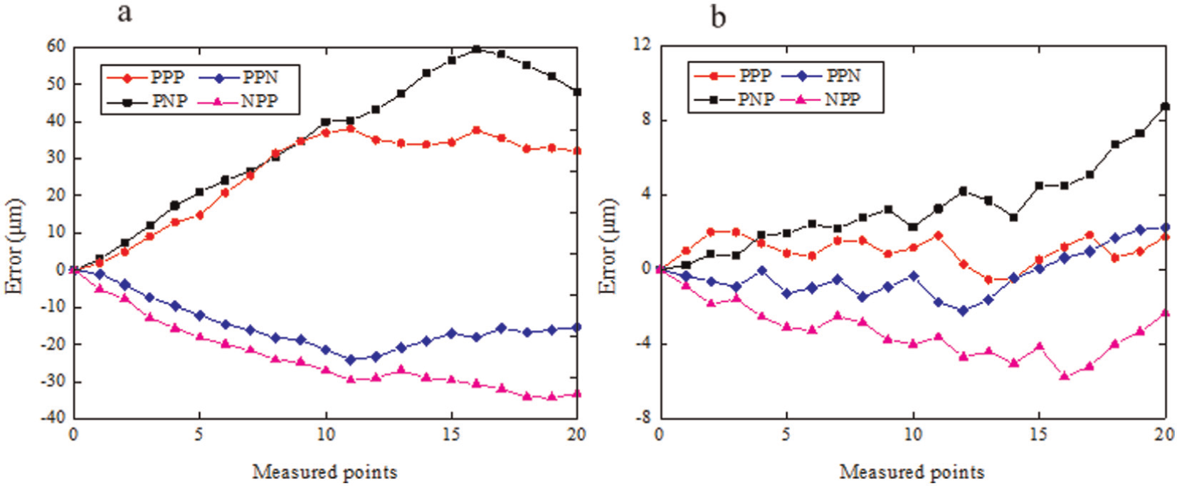
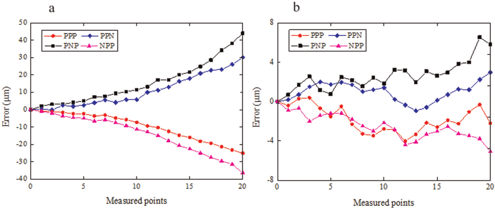
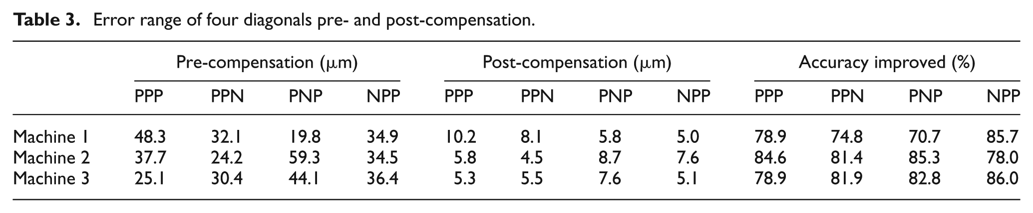
According to ISO 230-6:2002, 23 laser diagonal measurements were conducted to verify the volumetric accuracy of the machine tools. PPP, NPP, PNP and PPN are the four diagonals of the workspace. Here, P indicates the positive direction of translational axis and N the negative direction. Twenty target positions were chosen for each diagonal measurement. Figures 11–13, respectively, present the diagonal displacement accuracy of the three machine tools pre- and post-compensation. Table 3 shows the error range of four diagonals of the three machine tools pre- and post-compensation. The EDNC system integrated with the generalized model effectively improves the volumetric accuracy of multi-machine tools by at least 70%.
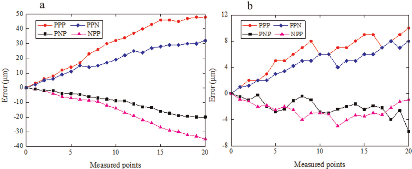
Diagonal displacement accuracy of three-axis machine tool 1: (a) pre-compensation and (b) post-compensation.
Diagonal displacement accuracy of three-axis machine tool 2: (a) pre-compensation and (b) post-compensation.
Diagonal displacement accuracy of the five-axis machine tool: (a) pre-compensation and (b) post-compensation.
Error range of four diagonals pre- and post-compensation.
Conclusions and future work
This article proposes a volumetric error generalized model and a distributed error compensation technique for multi-machine tools. The proposed generalized model can be applied to 4 types of three-axis machine tools and 12 types of five-axis machine tools. Compared with convectional generalized models, the proposed model is more detailed and convenient. The final kinematic model can be obtained without further human interventions by simply inputting the translational and rotary type numbers of the specific machine tool. Integrated with the generalized kinematic model, EDNC systems can accurately generate volumetric error maps and simultaneously compensate for volumetric errors of multi-machine tools. Compared with conventional compensation methods, the proposed approach has the advantage of high efficiency and accuracy to simultaneously compensate for volumetric errors of multi-machine tools. The EDNC technique also facilitates the condition monitoring of multiple machine tools.
The proposed generalized kinematic model is applicable only to 4 types of three-axis machine tools and 12 types of five-axis machine tools. Superior singular functions will be designed in future work to develop a more generalized model. The geometric errors of the rotary axes were not included in the experimental verification. Effective and convenient methods have been considered to precisely identify the 12 position-dependent geometric errors and 8 position-independent geometric errors of rotary axes.24,25 The thermal error compensation of multi-machine tools based on the EDNC system will be discussed in another article.
Footnotes
Appendix 1
Appendix 2
Declaration of conflicting interests
The authors declare that there is no conflict of interest.
Funding
This research was sponsored by the National Science Foundation Projects of P.R. China (Nos 51275305, 51175343), the Specialized Research Fund for the Doctoral Program of High Education (No. 20110073110041) and the Chinese National Science and Technology Key Special Projects (No. 2011ZX04015-031).