
Abstract
Gauges used for dimension inspection of critical components in various assemblies need to be precise and accurate. At the same time, the rate of inspection should be as high as possible for increased production. This is more so with regard to steering assemblies of automobiles. In automotive lines, the dimension inspection of the steering assemblies (constant velocity assembly) by Coordinate Measuring Machine would not be feasible as the process is slow and productivity would be affected. The proposed constant velocity gauging system can be considered as an alternative. The constant velocity assembly has six opening windows whose height is extremely critical. The accuracy of the component and the criticality demand complete inspection of the window height and identification of oversized window parts. The proposed cost-effective gauging system has a separate replaceable probe for each window to check the window height. All six windows are checked simultaneously to save production time. The qualified components and rejected components have been checked by first principles and on Coordinate Measuring Machine. Both have been found to be in good agreement.
Introduction
Functionality of the joints in steering is critical and hence the complex geometry. Constant velocity joints 1 also called CV joints are used in steering mechanisms of automotives. They are used in front wheel drive and many modern rear wheel drive cars. CV joints 2 are protected by a rubber boot. Cracks and splits in the boot could cause the joint to wear quickly. Wear and tear occur in the window, leading to oversized window. This may lead to malfunction of the CV cage, which could pose a major threat to functionality of the assembly. A typical CV ball cage part is shown in Figure 1.
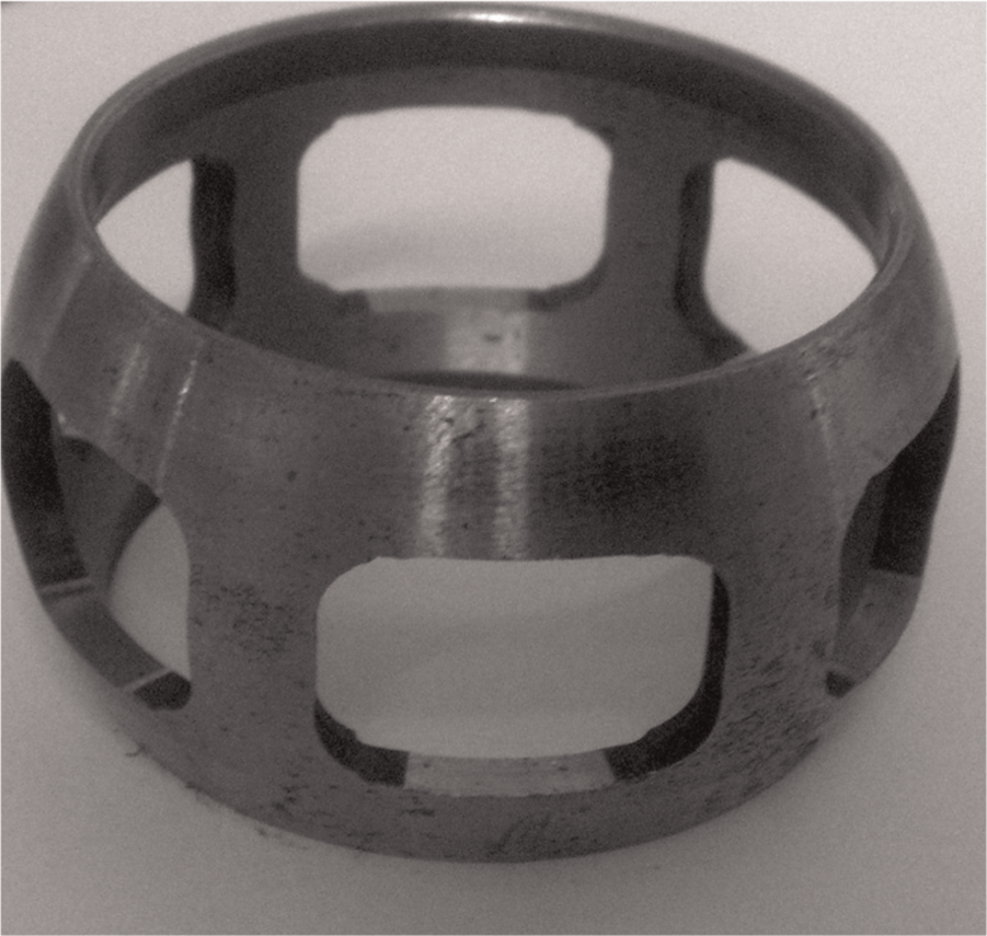
Component CV cage for which gauge is being developed.
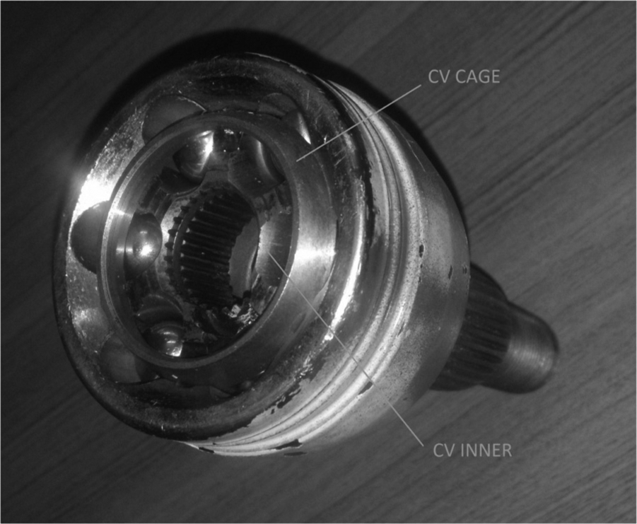
The CV sub-assembly where the subject component is assembled is shown in Figure 2. The component inside the CV outer is called as CV cage/ball cage. Inside CV cage, CV inner is present, where six balls are present in between both these parts. The balls should not pass through the window and the same would cause a part to be faulty and cause noise during run. Hence, the height of the window of the CV cage becomes extremely critical.
Component sub-assembly.
Design of gauging system
Previously, a pin/plug gauge was entered into every window and checked for finding defective window height. Every batch had a few components checked at random in Coordinate Measuring Machine (CMM). With this method, the checking used to be incomplete as there was always a chance of missing a window during pin gauge entry check. Use of pin gauge or CMM requires more time. It is also dependent on the skill of the operator, leading to lower production rates.
The need here was a gauging system that could provide a real-time check of the window height for improved productivity. Also, the gauge design should be of use during primary and secondary machining operation3,4, assembly operation stage and also during final inspection stage. An ideal gauge would be 5 reliable and accurate in function, easier to maintain, user friendly, easy to operate, easy interface to secondary systems, if required, and would provide quick results for high productivity.
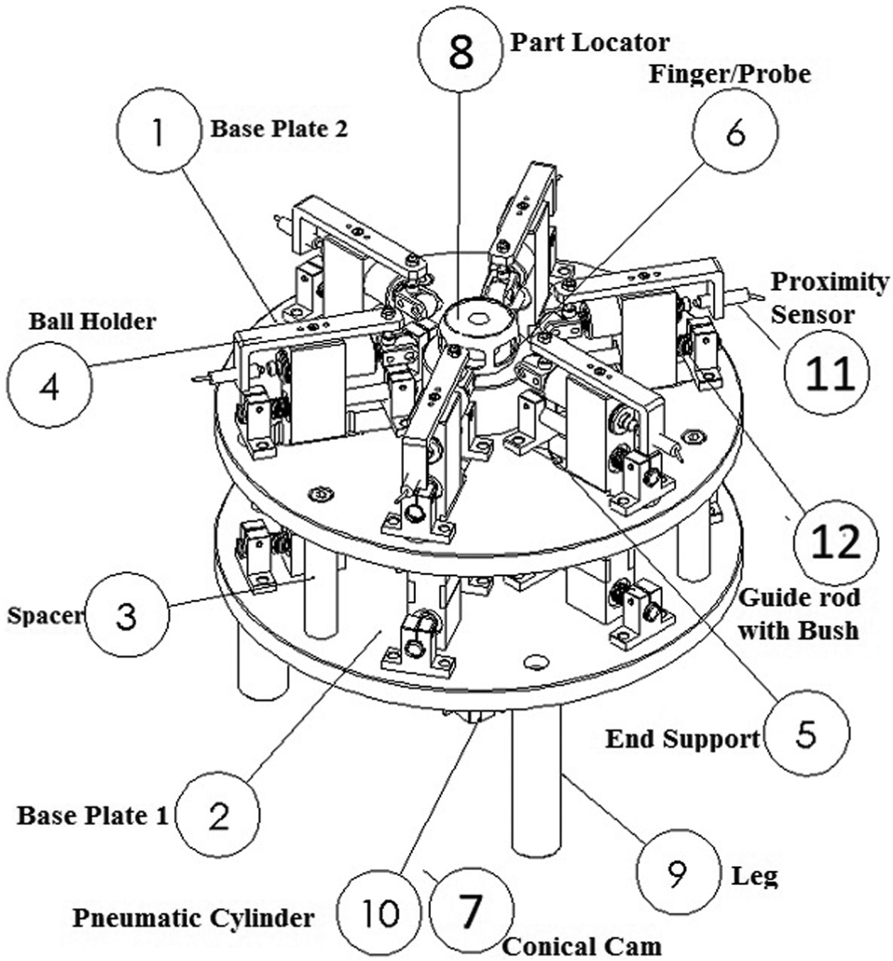
The gauging system shown in Figures 3 and 4 has specially designed finger/probe (Figure 5) that would check all windows simultaneously. Each of the probes is connected to a proximity sensor to sense faulty window height and to display the result (Accepted/Rejected), which can be improved to interface with secondary machining operation, inspection data logging and reporting the complete status of acceptance and rejection. The gauging system station has a base table to mount the gauging system, a panel box for controls, probe actuation pneumatically controlled with proximity sensors for position sensing and an indicator light emitting diode (LED) display which displays green light for accepted part and red light for rejected part.
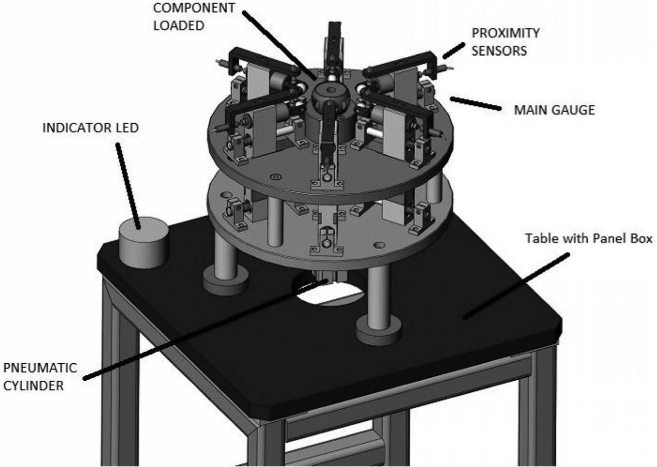
Gauging system.
Nomenclatures of the CV.
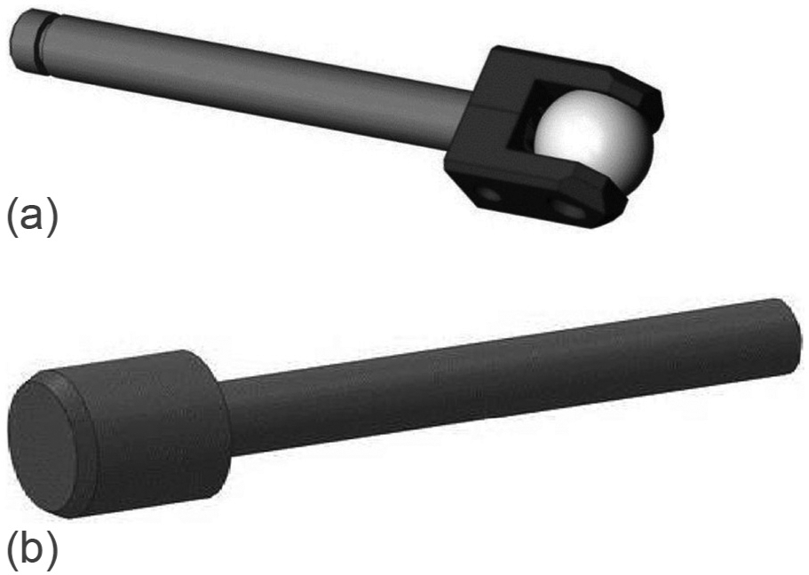
Finger/probe used in the gauge: (a) ball-type probe and (b) cylindrical-type finger/probe.
The gauge probe material used is EN31 and was chosen based on sufficient study. 6 The contact area of the probe was through hardened to HRC 55. The proximity sensors used are of ‘TAP’ make, with sensing distance of 1 mm being used in many gauging applications.
The probe used is of two types as shown in Figure 5(a) and (b). It could be cylindrical or spherical. Operationally cylindrical probe is preferred over the spherical one. Size of the probe is based on window height.
Operation
The specimen component to be tested (CV cage) is loaded on to the part locator at the required orientation. The pneumatic actuator moves the conical cam which in turn moves the six probes mounted on the slider simultaneously towards the component window. The disengaged and engaged probes have been shown in Figure 6(a) and (b). All the probes simultaneously enter their respective window. If the height of all the windows is of the design value, none would pass through their respective window and the green indicator light glows, resulting in acceptance of the component. If any one of the windows has height more than the design value, the probe passes through that window and the red indicator light glows, resulting in rejection of the component.
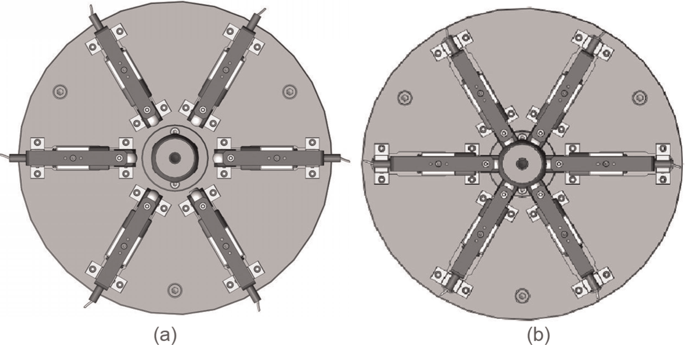
Component loaded: (a) probes not engaged to component and (b) probes engaged to check dimension.
The ball probe used in the system is the same ball that was used in the CV joint assembly. The advantages include simulating assembly condition and easy replaceability after wear out.
The image of the gauge developed is shown by Figure 7. The gauge was installed in a production line and a very large increase in productivity was recorded. The gauge is designed to detect oversized windows and not the undersized windows.
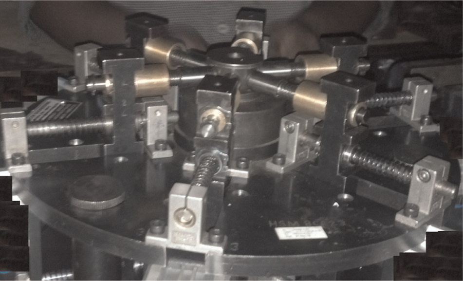
Gauging system assembly.
Gauge qualification/validation
The window height of more than 50 specimen components was tested using both CMM (Carl Zeiss Make; Resolution 0.001 mm) and a standard plug gauge (made as per IS Standards). It was found that the same three components were rejected by all the methods. The gauge also identified the faulty window.
The gauge was deployed in production line for over 6 months, and the comparison with the traditional gauging system was done. Measurements by using CMM, plug gauge and the current proposed gauge were in good agreement to detect oversized window height. Through multiple trials, the gauge repeatability/consistency was established. Table 1 shows the inspection data of sample specimen components tried before implementing the gauge on line. The test results of these components were found to be same as those of the proposed gauge.
Comparative results of CMM.
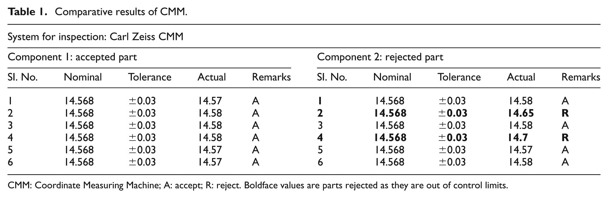
CMM: Coordinate Measuring Machine; A: accept; R: reject. Boldface values are parts rejected as they are out of control limits.
The output data of the gauge for a batch consisting of 50 samples have been checked in production line for gauge consistency and are shown in Table 2.
Comparative results (old gauge vs new gauge) – 50 samples checked on production line.
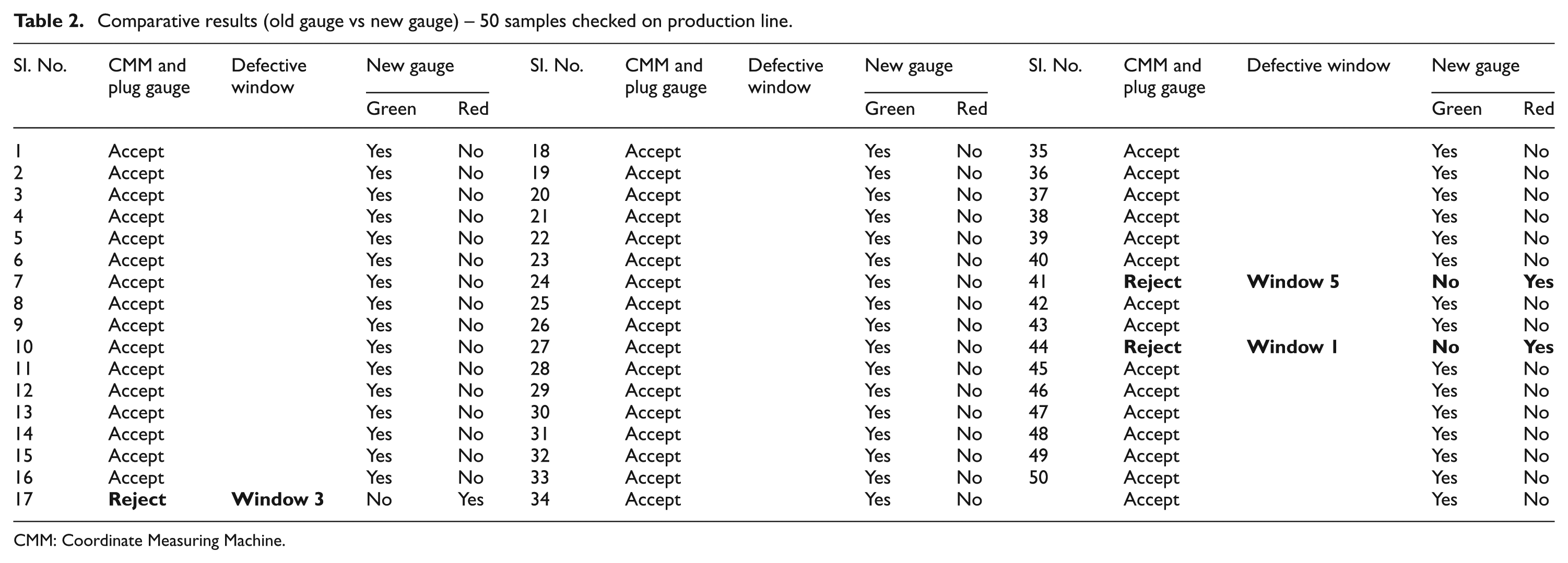
CMM: Coordinate Measuring Machine.
Also, the average time to check each component was computed. Average time for inspection using old gauging system was less than 8 s, whereas with the new gauging system, it was found to be less than 3 s. The new gauging system was found to be not only fast in identifying defective oversized components but also accurate and in-line with the certifying requirements. With the old gauging systems, there is always a possibility of a window that could be missed during inspection, but the same would not occur with the proposed gauge design. Average numbers produced after implementation of the old method for a period of 6 months was found to be 7094, and with the new gauge, it was 20,614.
Conclusion
The checking gauge can successfully identify oversized windows leading to increased productivity. No skilled operator is required for usage of system, and it scaled to accommodate different size components to a large extent with data logging.
The gauging system eliminates traditional methods of checking components. Traditional inspection techniques suffer from factors such as oversight and fatigue of the operator, due to which the accuracy of measurements was found to be unreliable. The gauging system ensures that all windows are checked simultaneously and chances of missing any window are prevented. It creates an accurate and error-proof checking technique, thus releasing only the correct parts to the assembly.
Footnotes
Acknowledgements
We sincerely thank few of our customers for providing an opportunity for development and implementation of the gauging system. Also, we thank our workplace DESICON Engineering and all staff who were involved in the project to put efforts and accurately manufacture my proposed design into product.
Declaration of conflicting interests
The authors declare that there is no conflict of interest.
Funding
This research received no specific grant from any funding agency in the public, commercial or not-for-profit sectors.