
Abstract
In the former research, the ultrasonic vibration technique had been adopted in the electrochemical micro drilling to exclude the reaction products in the inter-electrode gap, while the ultrasonic cavitation phenomenon generates micro jet with strong impulse force, which impacts the insulation coating and speeds up the damage of the insulation coating. In order to improve the service life of the sidewall-insulated electrode, the double insulating layers that consist of TiO2 ceramic coating and organic film were fabricated on the micro titanium electrode surface combining the micro-arc oxidation and electrophoresis coating techniques. The durability of the double insulating layers on the electrode sidewall was verified, and the influence of the ultrasonic vibration amplitude, machining voltage and electrolyte concentration on the machining accuracy with the sidewall-insulated electrode was analyzed through ultrasonically assisted electrochemical micro drilling experiments. The experimental results showed that the double insulating layers exhibited a strong durability in ultrasonically assisted electrochemical micro drilling. The machining was stable when the vibration amplitude of the workpiece was beyond a certain value; henceforth, the machining accuracy changed little with the increase in the vibration amplitude. The straightness of the hole can be effectively ensured, but the machining voltage and the electrolyte concentration should be lowered in order to reduce the overcut in the premise of stable machining.
Keywords
Introduction
Electrochemical micro drilling has advantages of no tool wear, stress-free and smooth surfaces of the machined hole, and the ability to machine electrically conductive materials regardless of their physical properties, which makes it an important process for fabricating micro hole on components applied in aerial, biomedical, electronic and micro-electromechanical system (MEMS) industry. However, it is difficult to exclude the reaction products in the inter-electrode gap (IEG) in electrochemical micro drilling, which causes non-stable machining. The ultrasonically assisted electrochemical micro drilling is proven to be an effective way to renew the electrolyte in the IEG,1–4 while the ultrasonic cavitation phenomenon generates micro jet with strong impulse force, which impacts the insulation coating and speeds up the damage of the insulation coating. Since the insulation coating plays an important role in restricting the stray current in electrochemical micro drilling, the machining accuracy will be affected if the insulation coating is damaged. So, it is necessary to propose an electrode sidewall insulation method that fabricates insulation layer with good durability in ultrasonically assisted electrochemical micro drilling.
Some insulation methods were proposed by the former lines of research. Polymers such as parylene were used for conformal coatings in a wide variety of applications. 5 Chemical vapor deposition (CVD) was used to deposit SiC on the sidewall of electrode. 6 The insulation coatings showed good insulation properties and strong resistance to most chemicals. However, general polymer coating processes through vapor deposition polymerization are carried out under vacuum and require specialized equipment, and the CVD process also requires additional equipment. Glass coating is widely used to insulate the side faces of electrodes, but the coating layer is too thick to use for micro electrodes. To reduce coating thickness, additional operation of etching is required. 7 The insulation materials were smeared on electrode surface through different methods. In the literature, 8 a diluted enamel droplet was dropped over the electrode end face. Since the electrode was placed vertically, the enamel flew down and finally covered the electrode sidewall. When the enamel coating dried up, the electrode end face was rubbed against a hard surface and was machined by electrical discharge machining (EDM) to remove the remaining enamel. In the literature,9,10 three layers of ceramic film and three layers of epoxy film were coated separately in sol–gel dipping. The spin-coating method was proposed to spread polymer on electrode surface through the end-rubbing process. 11 Hu et al. 12 proposed hydrophilic 704-silica material as the insulating material and insulated the side of the micro tool electrode by spin coating for fabrication of three-dimensional (3D) structure surface using hybrid process of micro EDM and electrochemical machining (ECM). Rathod et al. 13 presented a new approach for sidewall insulation of micro tool by dip-coating using liquid solution made of polymer and resin dissolved in isopropyl alcohol and use of acetone for opening the front end of the micro tool. Malapati and Bhattacharyya 14 presented experimental investigations into electromechanical machining (EMM) process during generation of micro channels on copper. The electrode sidewall was insulated using a synthetic material. Jain et al. 15 insulated the tip of sewing needle using liquid solution made by dissolving Perspex in chloroform and fabricated micro holes and micro channels on copper, utilizing the developed experimental setup. To prevent the dissolution of the material along the sidewalls of micro tool and to minimize the stray current effects during machining, sidewalls of micro tool were insulated using liquid solution made of polymer and resin dissolved in isopropyl alcohol. 16 These methods only depend on the adhesive force to connect the insulation coatings with the electrode substrate, which can hardly ensure the durability of insulation coating in ultrasonically assisted ECM. For example, the durability of epoxy resins and Teflon on electrode surface was analyzed through ECM; as a result, the durability of both was about 20 min. 17 It can be inferred that the durability of the coatings will be weakened under the ultrasonic condition. In Brusilovski’s 17 study, the diamond-like carbon (DLC) was used in ECM technology for cathode isolation purposes. The experimental results showed that the durability reached 180 min, but the process conditions for manufacturing DLC are harsh, which restricts the application of this method. The taper structure on electrode tip was proposed to enhance the adhesion between organic coating and electrode substrate. 18 But it is difficult to control the angle of the electrode tip especially when the micro electrode was used.
This article proposed a new method of fabricating insulation coatings on electrode sidewall, which showed good durability in ultrasonically assisted electrochemical micro drilling. The oxidation ceramic coating grew from the electrode substrate by the micro-arc oxidation (MAO) process. The adhesion strength of the oxidation ceramic coating was strong, and it has the excellent characters of insulation and corrosion resistance. Micro porosity existed in the oxidation ceramic coating, which resulted in the leakage in electrochemical micro drilling process. So, the electrophoresis coating technique was used for plugging the porosity. Thus, the double insulating layers that consist of oxidation ceramic coating and organic film were generated on the electrode sidewall combining the MAO and electrophoresis coating techniques. Then, a series of ultrasonically assisted electrochemical micro drilling experiments were conducted to verify the durability of the double insulating layers and to investigate the influence of ultrasonic vibration amplitude, machining voltage and electrolyte concentration on machining accuracy.
The electrode sidewall insulation method
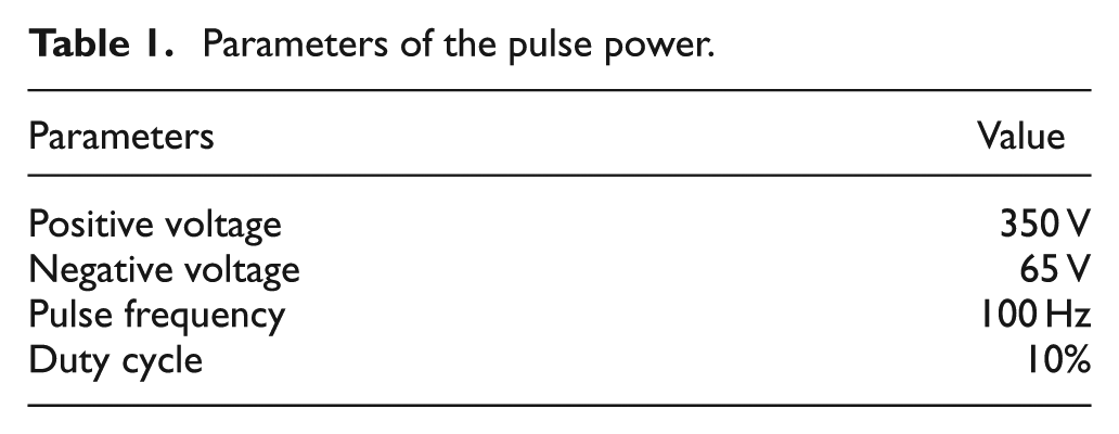
MAO is a very complicated and multifactor-controlled process. 19 In the process, the specimens as positive electrode are immersed in a certain solution, the electrolytic bath as negative electrode is filled with electrolyte and a large number of short-lived micro-arc discharges, caused by dielectric breakdown of oxide coatings, occur on the entire specimen surface when the supplied voltage is higher than a critical value. The surface coatings contain many discharge channels, and the size of the channels increases along with the treatment time, voltage and electric current in the MAO process, such that the coatings formed by MAO are essentially porous. The melted materials are ejected out of the channel and cooled rapidly due to their immediate contact with the electrolyte, which leads to an overall increase in the coating thickness. MAO is commonly used to modify the surface of aluminum, magnesium, titanium and the alloy of them with an oxidation ceramic coating. Among these metals, titanium has the strong ability of resisting to pitting corrosion, acid corrosion, stress corrosion and alkali erosion. Therefore, this research chose titanium as the electrode material. There was titanium wire in the market, and the smallest diameter of the titanium wire was 0.3 mm. So, this study chose the titanium wire with a diameter of 0.3 mm as the electrode. The electrode was first treated with the MAO process. Figure 1(a) shows the schematic diagram of the MAO process, and Figure 1(b) shows the self-made MAO apparatus. The electrode was immersed in a certain solution that was in the stainless steel electrolytic bath. The dimension of the stainless steel electrolytic bath was 400 × 400 × 300 mm3. The electrode was vertically put into the center of the stainless steel electrolytic bath. The electrode and the stainless steel electrolytic bath were connected to the poles of the power. When the positive voltage was applied to the electrode, the spark discharge began on the electrode surface and the TiO2 ceramic coating gradually grew from the titanium substrate. The electrolyte was composed of NaAlO2 (10 g/L) and Na3PO4 (5 g/L). The treating time was 15 min. Table 1 shows the pulse power parameters of the MAO process. The bipolar pulse power was used, the output waveform diagram of which is shown in Figure 2. U p represented that the positive voltage was exerted on the titanium electrode. U n represented that the reverse voltage was applied to the titanium electrode. The reverse voltage has the function of avoiding the repeated breakdown at the same sites, which induces the generation of large discharge pores. 20
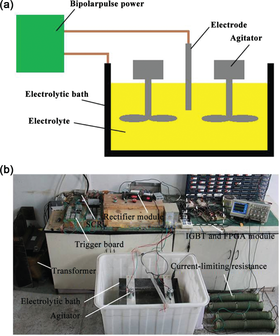
MAO treatment for the titanium electrode: (a) schematic diagram of the MAO process and (b) actual picture of the MAO apparatus.
Parameters of the pulse power.
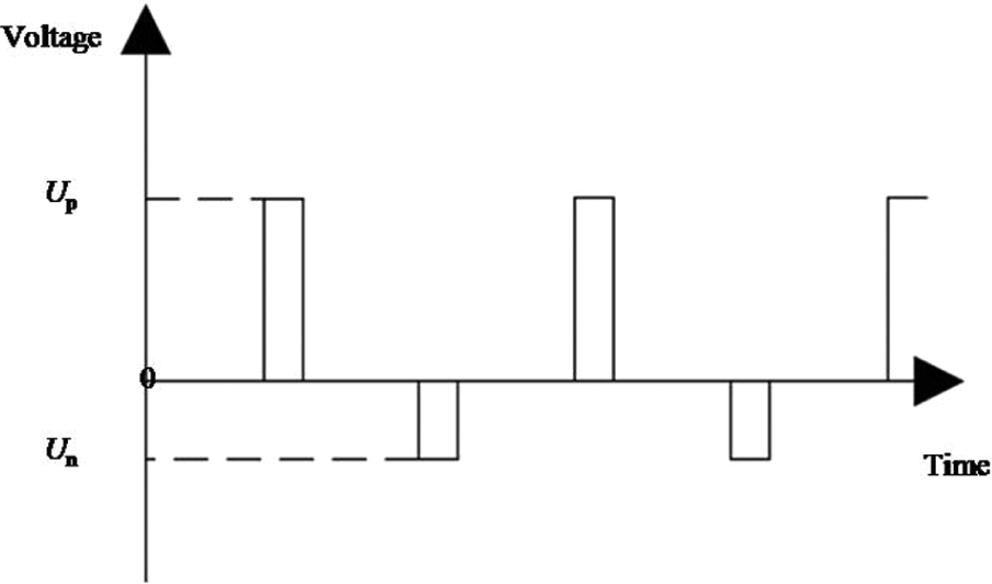
Waveform diagram of the pulse power.
Figure 3 shows the phenomenon of the MAO process. It can be seen that the spark is uniformly distributed on the electrode surface. Figure 4 shows the electrode before and after MAO treatment. It can be seen that a white layer was generated on the electrode surface, of which the main composition is TiO2 ceramic. The thickness of TiO2 was 5 µm. The adhesion between TiO2 ceramic coating and electrode substrate was strong because TiO2 ceramic coating in situ grew from the electrode substrate, and the combination of TiO2 ceramic coating and electrode substrate belongs to metallurgical bonding. Figure 5 shows the surface micro-topography of the TiO2 ceramic coating. It can be seen that micro porosity existed in the TiO2 ceramic coating. When the electrode worked as cathode in electrochemical micro drilling, the ions in the electrolyte will pass the TiO2 ceramic coating through the micro porosity, resulting in the current leakage.
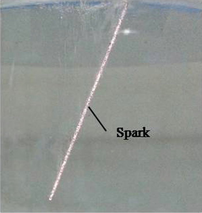
Phenomenon of the MAO process.
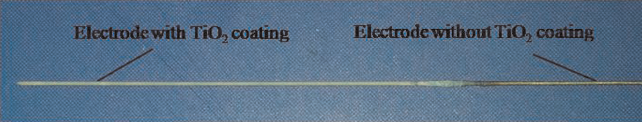
The electrode before and after the MAO process.

The surface micro-topography of the TiO2 ceramic coating.
In order to improve the insulating performance of the electrode sidewall, the electrophoresis coating technique was applied. The electrode with TiO2 ceramic coating on its surface and an auxiliary electrode were put into the electrophoresis paint. The material of the auxiliary electrode was stainless steel. The direct current (DC) voltage with a value of 100 V was applied to the two electrodes for 60 s. Then, the electrode was taken out of the electrophoresis paint and dried at 180 °C for 25 min. Thus, the double insulating layers were generated on the electrode surface (Figure 6). The cross-sectional micro-topography of the double insulating layers is shown in Figure 7. The organic film thickness was 9 µm. It can be seen that the organic film implanted into the micro porosity of the TiO2 ceramic coating as shown in the region marked by a circle in Figure 7. This structure characteristic can protect the organic film from peeling off. Experiments were conducted to verify the insulating performance of the double insulating layers. The electrode with double insulating layers on its surface worked as cathode in NaNO3 solution, of which the mass fraction was 10%. The applied DC voltage was from 0 to 80 V. No bubble was generated from the electrode surface until the voltage reached 80 V. The experimental results show that the double insulating layers have the excellent insulating performance. In the electrochemical micro drilling process, the applied voltage was usually lower than 6 V. So, the double insulating layers were fully qualified for electrochemical micro drilling with the consideration of the insulation ability. The electrode was implanted into ceresin wax and polished to remove the double insulating layers on the end surface (Figure 8(a)). Then, the ceresin wax was melted by water at 80 °C. Thus, a sidewall-insulated electrode was generated as shown in Figure 8(b).
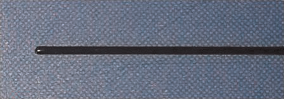
Electrode with double insulating layers.
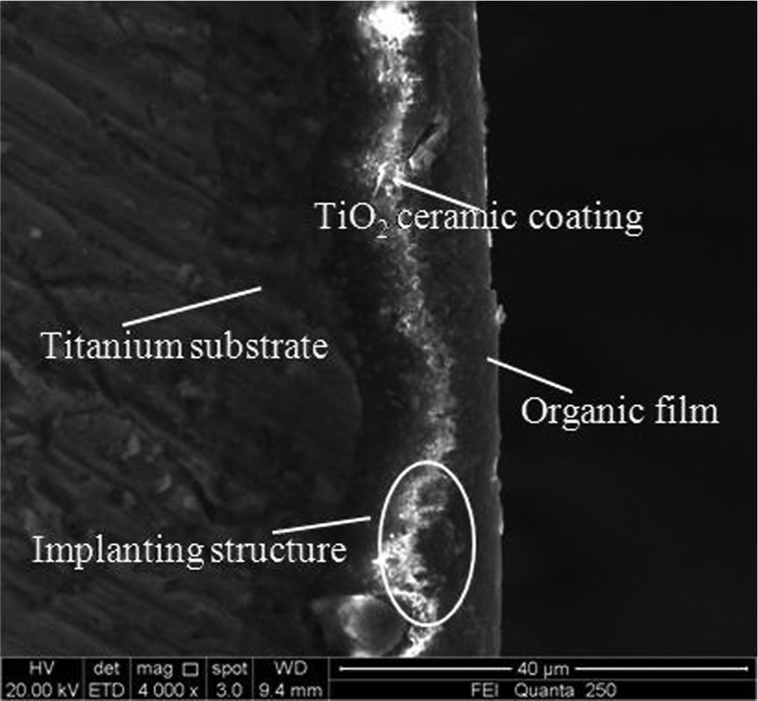
The cross-sectional micro-topography of the double insulating layers.
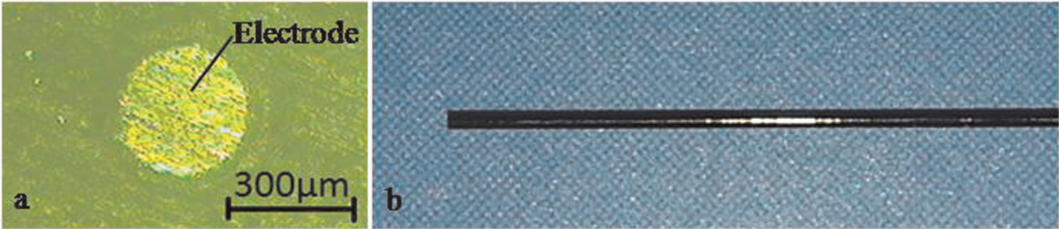
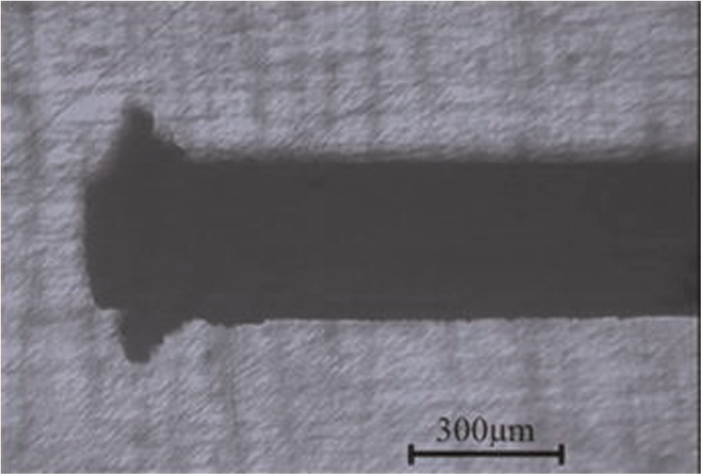
Sidewall-insulated electrode: (a) the polished end surface of the electrode and (b) the fabricated sidewall insulated electrode.
Ultrasonically assisted electrochemical micro drilling device
This research exerted the ultrasonic vibration on the workpiece instead of the electrode in order to avoid the deviation of the micro electrode when the power of the ultrasonic equipment was large. The experimental device is shown in Figure 9. The workpiece was fixed onto the ultrasonic vibration platform. The resonant frequency of the ultrasonic vibration platform was 28 kHz, and the power of the ultrasonic generator was 0–600 W. The amplitudes of the ultrasonic vibration platform can be adjusted from 0 to 5 µm by changing the power of the ultrasonic generator. The amplitude of the ultrasonic vibration platform was represented by the power of the ultrasonic generator in this article. In order to take away the reaction products, such as gas bubbles, sludge and Joule heat from the machining zone, the clean electrolyte was directed through the nozzle to the machining zone with a low-pressure setting without affecting the stability of the micro tool. A DC supply with an output voltage of 0–150 V was used for providing the electric energy for the electrochemical micro drilling process.
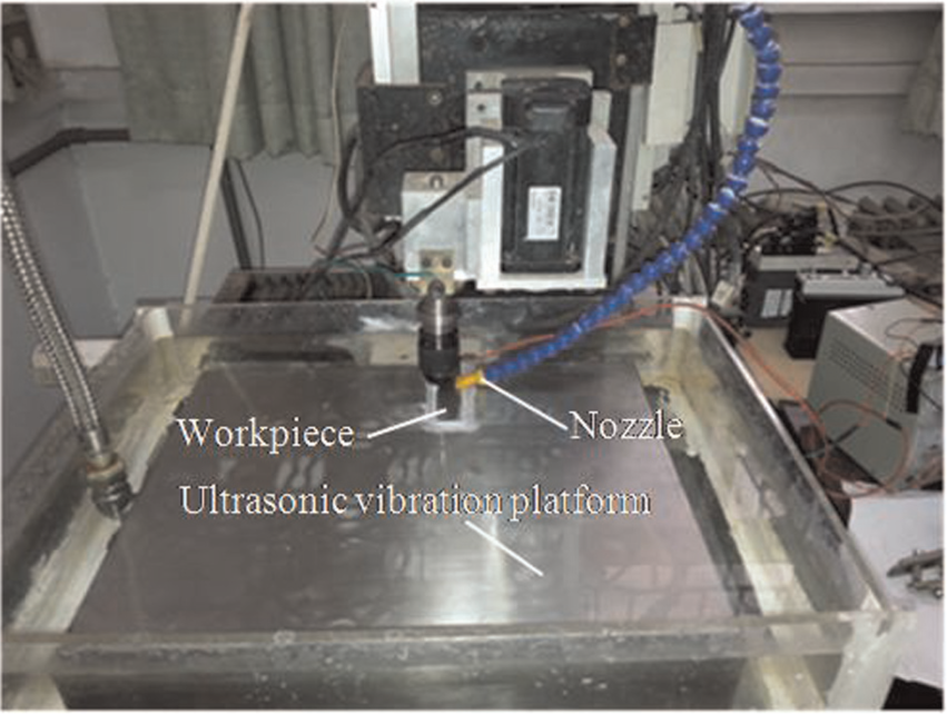
The ultrasonically assisted electrochemical micro drilling device.
Durability of the double insulating layers
Experiments were conducted to verify the durability of the double insulating layers in ultrasonically assisted electrochemical micro drilling. The electrode sidewall was coated with the double insulating layers through the method introduced in section “The electrode sidewall insulation method.” The applied voltage was 10 V, and the electrolyte was NaNO3 with a concentration of 20 g/L. The input power of the ultrasonic vibration platform was 300 W. The workpiece specimen was stainless steel 304 with a thickness of 0.5 mm. The machining depth of each hole was 0.32 mm, and the initial distance between electrode bottom and workpiece surface was 50 µm. The feed rate of the electrode was constant at 0.037 mm/min. A series of blink holes were machined until the double layers were broken. In most of the machining time, the current was stable if the double insulating layers were integrated. When the double insulating layers were damaged, the current increased and stabilized at a larger value. But considering the randomness of electrochemical micro drilling, the electrode will be checked through microscope to ensure that the double insulating layers were destroyed. If the double insulating layers were still integrated, the machining will be continued. The double insulating layers broke when the machining process persisted for 105 min, and the fabricated holes are shown in Figure 10. It can be seen that the double insulating layers were broken during machining the 11th hole, which resulted in the increase in the overcut of the 12th hole. This research considered that the overcut of the hole equaled the radius difference between the hole and the electrode. The diameters of the fabricated holes were measured through the equipment, as shown in Figure 11. The workpiece with fabricated holes was placed on the microscope slide. Each hole was magnified 150 times by the microscope, and the picture was input into the computer through the electronic eyepiece. Then, the diameter of the hole was measured by the measurement software installed on the computer. The measurement method was to pickup three points on the profile of the hole, and then the software will calculate the diameter of the hole. The overcut of each hole is shown in Figure 12. It can be seen that the holes have good consistency before the double insulating layers were broken. In comparison, the electrode with the organic film coating can only be kept integrated for 10 min in ultrasonically assisted electrochemical micro drilling.
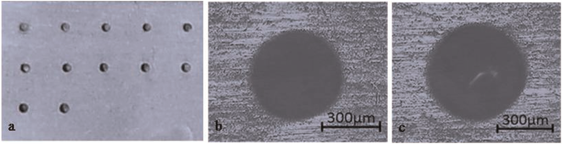
Fabricated holes with the same one electrode: (a) the integrity of the holes, (b) the micrograph of the first hole and (c) the micrograph of the last hole.
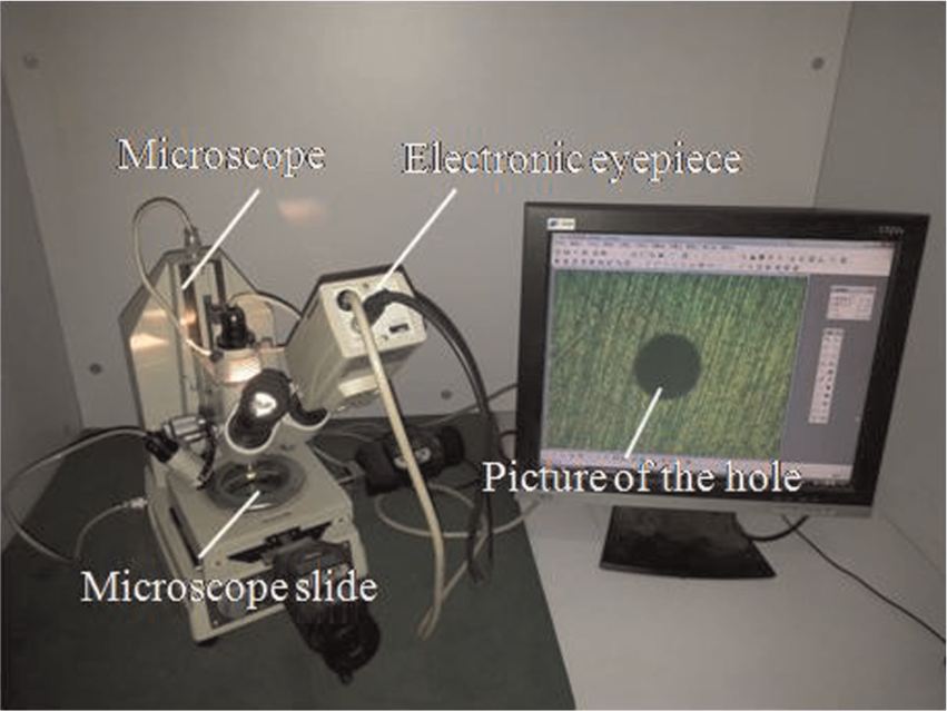
Equipment for measuring the diameter of the hole.
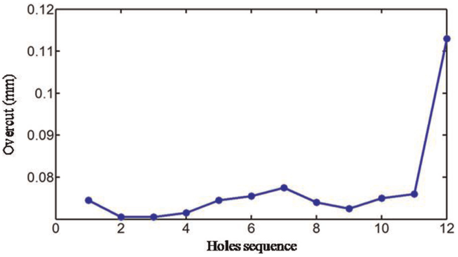
Overcut of the fabricated holes.
Effects of workpiece vibration amplitude on the accuracy of electrochemical micro drilling
Experiments were conducted to study the influence of the workpiece vibration amplitude on the accuracy of electrochemical micro drilling with sidewall-insulated electrode. The input powers of the ultrasonic vibration platform were 100, 200, 300 and 500 W, respectively. The workpiece specimen was stainless steel 304 with a thickness of 0.5 mm. Other conditions were the same as those described in section “Durability of the double insulating layers.” Through-holes were manufactured. With the input power of 100 W, the short phenomenon occurred when the machining depth was 0.15 mm and the electrode was burnt resulting in the damage of the double insulating layers as shown in Figure 13. The machining was stable when the input powers were 200 and 300 W, respectively, and the fabricated through-holes are presented in Figure 14. It can be seen that the shape of the two holes was good. The overcut of the holes entrance was 70, 75 and 72 µm, and the diameter difference between the entrance and the exit of the holes ΔD was 8, 7 and 10 µm, respectively. The experimental results indicated that the increase in the workpiece vibration amplitude is benefit to improve the exclusion of reaction products in the inter-electrode and thus receive a good machining accuracy. Once the workpiece vibration amplitude is beyond a certain value, the machining overcut and ΔD change little along with the workpiece vibration.
The burnt electrode.
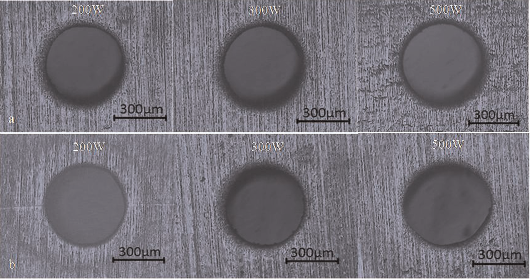
Micrograph of the fabricated holes: (a) entrance of the holes and (b) exit of the holes.
Effects of machining voltage on the accuracy of electrochemical micro drilling
Experiments were conducted to study the influence of the machining voltage on the accuracy of the hole fabricated by ultrasonically assisted electrochemical micro drilling with sidewall-insulated electrode. The machining voltages were 7, 10, 12, 14 and 16 V, respectively, and the electrolyte was NaNO3 with a concentration of 10 g/L. Other conditions were the same as those described in section “Durability of the double insulating layers.” Through-holes were manufactured. The experimental results are shown in Figures 15 and 16. It can be seen that the overcut of the holes entrance increased along with the machining voltage (Figure 15). The diameter difference between the entrance and the exit of the holes ΔD was less than 10 µm, and there was little influence of machining voltage on ΔD (Figure 16). When the machining voltage increased to 16 V, discharge happened when the machining depth was just 0.1 mm. The experimental results show that the stray current was effectively restrained in the area between the electrode end face and the bottom of the hole, as shown in Figure 17. Thus, the sidewall of the hole between the electrode end face and the entrance of the hole will not be continuously removed during machining. So, the straightness of the hole can be ensured, while there was still the stray current on the edge of the electrode end face. The stray current enhances along with the machining voltage and results in the increase in the diameter of the hole. If the machining voltage is over-large, massive bubbles were generated in short time and it is difficult to effectively remove them from IEG through workpiece vibration, which results in an increase in inter-electrode resistance and causes frequent discharge between the electrode and the workpiece.
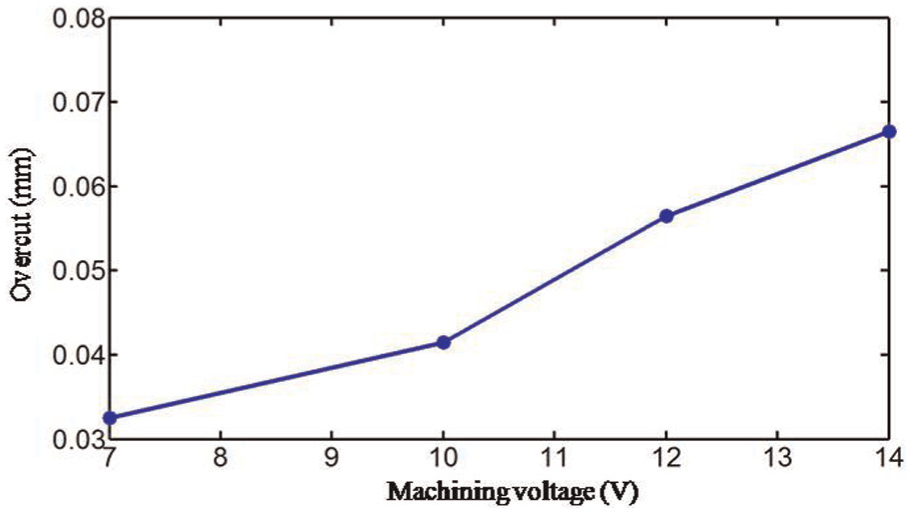
Relationship between the overcut of the holes entrance and machining voltage.
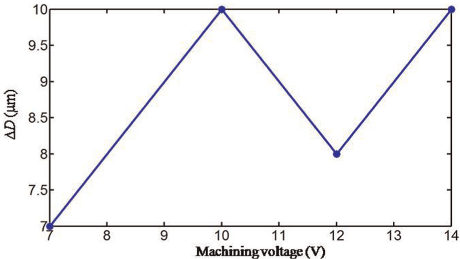
Relationship between ΔD and machining voltage.
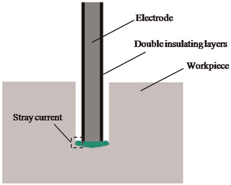
Schematic diagram of the electric-field distribution in the inter-electrode gap.
Effects of electrolyte concentration on the accuracy of electrochemical micro drilling
The influence of electrolyte concentration on the accuracy of hole fabricated by ultrasonically assisted electrochemical micro drilling was analyzed. The electrolyte concentrations were 10, 20, 30 and 40 g/L, respectively. The workpiece specimen was stainless steel 304 with a thickness of 0.5 mm. Other conditions were the same as those described in section “Durability of the double insulating layers.” Through-holes were manufactured. The experimental results are shown in Figures 18 and 19. It can be seen that the overcut increased along with the electrolyte concentration (Figure 18). The ΔD of each hole was less than 10 µm, and no identified relationship between the electrolyte concentration and ΔD was found (Figure 19). It can be seen that the influence of electrolyte concentration on the accuracy of electrochemical micro drilling was similar to the influence of machining voltage.
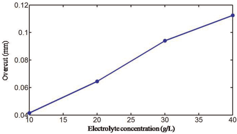
Relationship between the overcut of the holes entrance and electrolyte concentration.
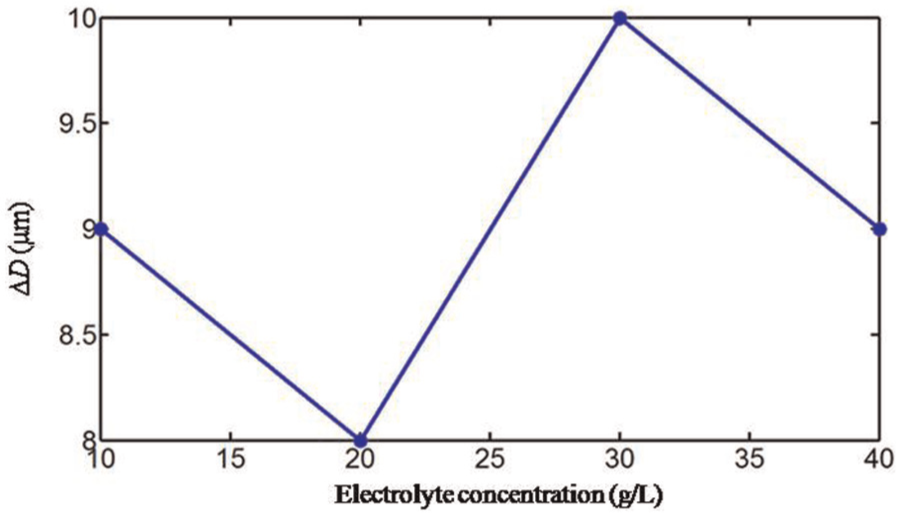
Relationship between ΔD and electrolyte concentration.
Conclusion
This research proposed a new electrode sidewall insulation method to improve the durability of the insulating layer in ultrasonically assisted electrochemical micro drilling. The influence of the ultrasonic vibration amplitude, machining voltage and electrolyte concentration on the machining accuracy was analyzed through experiments. The following conclusions were drawn:
The double insulating layers can be successfully fabricated on the sidewall of micro titanium electrode with a diameter of 0.3 mm through MAO and electrophoresis coating techniques. The durability of the double insulating layers in ultrasonically assisted electrochemical micro drilling is significantly improved compared to the organ film.
The increase in ultrasonic vibration amplitude of the workpiece is benefit for excluding the reaction products in electrochemical micro drilling. If the amplitude of the workpiece is large enough to ensure the stable machining, the machining accuracy of the hole will change little along with the increase in the amplitude of the workpiece. So, it is not necessary to further increase the workpiece vibration amplitude once the electrochemical micro drilling is stable.
The stray current is effectively restrained in the area between the electrode end face and the bottom of the hole by the double insulating layers, thus the straightness of the fabricated hole can be ensured. But there is still stray current on the edge of the electrode end face, and it enhances along with the machining voltage and electrolyte concentration, which results in the increase in the diameter of the hole. So, the low machining voltage and electrolyte are suggested to achieve high machining accuracy on the premise that the machining is stable.
Footnotes
Declaration of Conflicting Interests
The author(s) declared no potential conflicts of interest with respect to the research, authorship, and/or publication of this article.
Funding
The author(s) disclosed receipt of the following financial support for the research, authorship, and/or publication of this article: The authors would like to thank the National Natural Science Foundation of China (51175295) for this study.