
Abstract
In high-speed gas metal arc welding process, weld defects like humping bead and undercutting appear and the weld bead quality worsens when welding speed exceeds a critical value. The previous investigations have proved that the backward flowing molten jet with high momentum in the weld pool is responsible for the formation of humping bead in high-speed gas metal arc welding. In this study, an external electromagnetic field generator is developed to change and control the flow condition in the weld pool and suppress the occurrence tendency of the humping bead. Bead-on-plate welding experiments are performed on mild steel Q235 test-pieces, and the influences of the exerted magnetic strength on the arc behavior, the fluid flow inside the weld pool, the weld bead shape and the weld penetration and width are investigated. The reason why the external electromagnetic field can suppress the humping bead is explained. The results show that external magnetic field can remarkably adjust the weld pool fluid flow field and decrease the momentum of the backward flowing molten jet. Therefore, weld defects like humping bead and undercutting can be effectively suppressed, the quality of weld bead is remarkably improved, and the critical welding speed is notably increased.
Introduction
Arc welding processes are still the most widely used materials joining technologies in manufacturing industry.1–4 To improve the competitiveness in today’s industry environment, manufacturing enterprises must consistently seek for higher welding speed to achieve higher productivity.1,5 However, the weld bead quality is worsened, and severe geometric defects such as humping bead begin to occur if the welding speed is increased to some extent.6,7 That is to say, there exists a critical welding speed beyond which humping bead will deteriorate the weld quality in gas metal arc welding (GMAW) and gas tungsten arc welding (GTAW). The welds with humps cannot satisfy the requirements of manufacturing industry, and effective measures must be taken to avoid or suppress the occurrence of humping bead. In recent years, special welding equipment and processes have been developed to obtain high-quality welds at high welding speed, such as tandem or triple wire GMAW or GTAW and hybrid welding.8,9 Although these modified welding processes are able to increase the welding productivity without sacrificing the weld quality, they have some drawbacks. For example, some rely on special shielding gas mixtures and expensive equipment, and others add difficulties in operation and process optimization. Since GMAW is one of the most economical, efficient and versatile fusion welding processes, 10 it is of great significance to develop low-cost and easy-operation high-speed GMAW.
Experimental observations have demonstrated that there is a strong backward flow of molten metal inside the weld pool during high-speed GMAW.6,7 The high momentum of the backward flow of molten metal results in the formation of humping bead. High-speed GMAW usually uses high level of welding current to maintain the required heat input. Because the arc pressure is proportional to the square of the welding current, a severely depressed region is created in the front of the weld pool by the combined actions of the arc force and the momentum of the droplets from the electrode. The molten metal layer beneath the arc is very thin, and the molten metal is pushed to the back of the weld pool where it accumulates and grows into a swelling. After solidification, humped bead forms.5–7,10 To suppress humping bead, it is crucial to reduce the momentum of the backward molten metal flow in the weld pool. Some modified GMAW used two wires to expand the action area of the arc force so that the backward molten metal flow in the weld pool is weakened.11–13 But two welding torches make the equipment and operation more complex. There is current flowing through the molten metal in the weld pool. If an external magnetic field is exerted into the molten metal inside the weld pool, the generated electromagnetic force can change the flow velocity of molten metal, and the momentum of the backward molten metal flow in the weld pool may be decreased by such a simple and practical way.
Magnetic control methods were proposed around 1960s 14 and were implemented in arc welding to control the arc and the weld pool behaviors.9,14,15 Li’s group used external magnetic field to improve the weld quality in resistance spot welding of advanced high-strength steels, and promising results were obtained.16–19 For arc welding, though external magnetic field has been employed in adjusting the arc behavior,9,14 stirring the weld pool to refine grain size 20 and supporting the weld pool,21,22 it has not been tried to control and change the fluid flow in weld pool to realize high-speed GMAW. Kern et al. 23 used magneto-fluid dynamic mechanism in laser welding to change flow conditions in weld pool so as to stabilize them and achieve greater welding speed. However, the weld pool in laser welding is very small in volume, and there is no current passing through the laser weld pool. For high-speed GMAW, the weld pool is much larger in volume, and there is current flowing inside the weld pool. The interaction between the current in the weld pool and the external magnetic field is more complicated, and the adjustment effect of the electromagnetic force on the flow conditions in the weld pool may be more powerful.
In this study, a self-developed magnetic field generator is applied to control the backward flow jet of molten metal inside the weld pool in high-speed GMAW. Both the arc and weld pool are observed by a vision sensor under the conditions with and without actions of external magnetic field. It is found that exerted electromagnetic force is able to change and control the relative position between the arc axis and the weld pool, the direction of the droplet transfer and the flow status of the molten metal in weld pool, so that the momentum of the backward flow of molten metal is reduced in the weld pool. Consequently, the humping bead is dramatically suppressed.
Experimental setup
As shown in Figure 1, the experimental system consists of a control computer, a GMAW power source, a work-table, a magnetizer (magnetic field generator), a high-speed vision sensor and a data acquisition subsystem. The magnetizer includes the two coils (excitation winding) and an excitation power source. Each coil has 270 turns. The wire of diameter 2.3 mm is winded around the electrical iron bar with diameter 20 mm and length 145 mm. The distance between the centers of two coils is 38 mm. The excitation current is 0–8 A, and the corresponding magnetic flux density is 0–80 mT. The two coils are assembled under the work-table and located in the vertical plane passing the welding torch. There is a 5-mm distance from the bottom surface of the backing plate to the top end of the coils. During the welding process, both the torch and the coils are stationary, while the workpiece travels along the welding direction. For generating the electromagnetic force toward the front edge of weld pool, the external magnetic field should be parallel to the welded plate but perpendicular to the welding line.
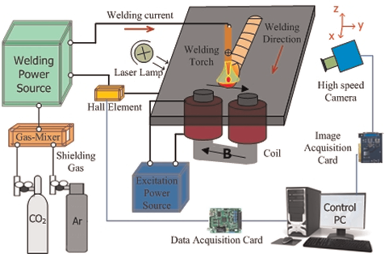
Schematic of experimental system.
During the welding process, the behaviors of the arc and the weld pool are observed by a mono high-speed camera equipped with filter in the visible light region. The sampling frequency is about 836 frames per second (fps). The camera aims at the target from one side of the work-table, that is, the axis of the camera is perpendicular to the welding direction, and the viewing angle is about 45° with respect to the workpiece surface.
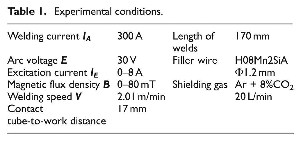
The workpieces are mild steel Q235 plates of 3 mm thickness, and the filler wire is steel wire H08Mn2SiA. The experimental conditions are listed in Table 1. The bead-on-plate welds are made under different conditions.
Experimental conditions.
Electromagnetic control of flow condition in weld pool
Figure 2 shows the action mechanism of external electromagnetic force applied to high-speed GMAW process. The electromagnetic force, current flux density and magnetic flux density are represented by
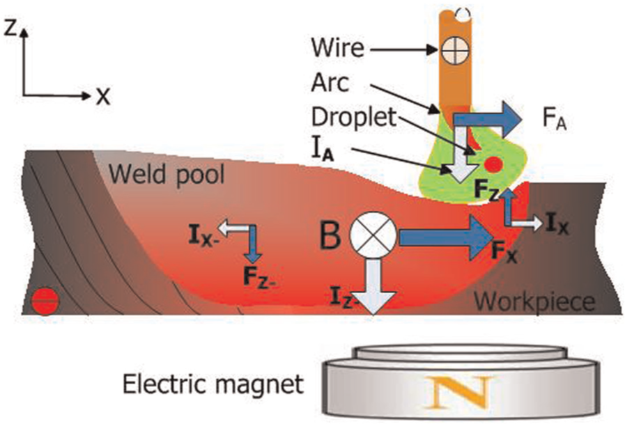
Action principle of external electromagnetic field (⊗: the magnetic field toward y-axis).
Before the arc ignites, the magnetic flux density is localized on the workpiece and is just about 1 mT in the air between the wire end and the workpiece, because mild steel has the magnitude of magnetic permittivity more than 1000 times higher than that of the air at ambient temperature. However, once the arc ignites, much heat reaches the workpiece, and the temperature of the base metal surrounding the weld pool exceeds the Curie point, which causes the magnetic permittivity of mild steel to be almost the same as that of the air. In such a case, the magnetic flux density in the arc region can be much larger than 1 mT. So, the effect of the external magnetic field on the arc and droplet cannot be neglected. The interaction of downward welding current
Results and discussion
The high-speed camera is used to observe the arc and the weld pool during the welding process. Figure 3 shows the images of the arc and weld pool under different values of magnetic strength. When there is no external magnetic field (B = 0) as shown in Figure 3(a), the arc keeps almost straight and the droplets are transferred into the weld pool vertically. Under the action of the arc pressure and droplet impact, the weld pool surface is depressed and a crater forms beneath the arc. The molten metal is pushed into the boundary of the crater. The molten metal in the front and two sides of the crater flows backward along the side channels surrounding the arc and merges with the molten metal behind the crater and forms the backward flow jet with higher velocity and momentum. Such a backward flow jet of molten metal inside the weld pool with high momentum makes a gradually accumulated molten metal at the rear part of the weld pool, and a hump bead occurs. It can be seen from Figure 3(a) that the flowing channel of backward flow jet is wider, which appears as the uniform bright zone.
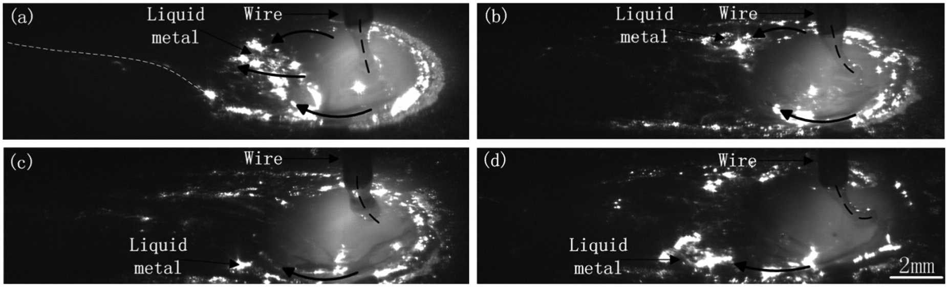
Effect of magnetic flux density on the arc and molten pool: (a) B = 0 mT, (b) B = 40 mT, (c) B = 60 mT and (d) B = 80 mT.
When the external magnetic field is applied, as shown in Figure 3(b)–(d), the arc is inclined forward due to the forward electromagnetic force (
Figure 4 shows the weld bead morphology at different levels of external magnetic strength. Without the external electromagnetic field, humping bead appears, as shown in Figure 4(a), and undercutting occurs together. The spacing between two humps is about 35 mm. After the external electromagnetic field is applied, the quality of weld formation is much improved, and no humping bead occurs. Good and smooth weld bead is obtained when the magnetic strength B = 60 mT, as shown in Figure 4(c). If B < 60 mT or B > 60 mT, undercutting still appears at some positions (see Figure 3(a) and (b)). If B = 80 mT, spatter is severe, and the weld bead is not uniform (see Figure 4(d)). Although the humping bead is suppressed by the external magnetic field, it causes some spatter, as shown in Figure 4(b)–(d). This side effect may have resulted from the interference of the external field on metal transfer. The investigation is still on-going to avoid the spatter.
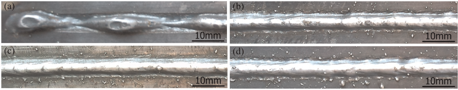
Weld bead morphology at different levels of magnetic strength: (a) B = 0 mT, (b) B = 40 mT, (c) B = 60 mT and (d) B = 80 mT.
The test samples are made from the weld bead in Figure 4. Figure 5 demonstrates the macrographs of the welds. Figure 5(a) is the transverse cross section at the valley when B = 0. When the external magnetic field is applied, there is smooth transition between the deposited metal and the base metal, and symmetric welds are obtained, as shown in Figure 5(b) and (c). If the magnetic strength is too high (B = 80 mT), the transition between the deposited metal and the base metal gets worsened, and there is a step on the left-hand side and a undercutting at the right-hand side, as shown in Figure 5(d). Clearly, there exists a corresponding optimum scope of the magnetic strength for a set of welding process parameters. Under the action of the matched external magnetic field, the fluid flow condition inside the weld pool is adjusted, and good weld bead quality is obtained.
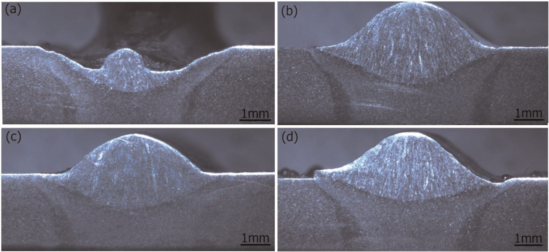
Cross-sectional shape of weld beads at different magnetic strengths: (a) B = 0 mT, (b) B = 40 mT, (c) B = 60 mT and (d) B = 80 mT.
Figure 6 shows the effect of the external magnetic strength on the weld width and penetration. With the increase in the external magnetic strength from 40 to 80 mT, the weld penetration decreases from 1.2 to 0.9 mm, while the weld width increases from 6.6 to 7.4 mm. This is because a higher magnetic strength causes a thicker molten layer in the front part of the weld pool which weakens the “digging” action from the arc and the impacting droplets beneath the arc. The weakened digging action makes a shallower weld pool, and the heat inside the pool has to transfer in transverse direction. Thus, the weld width expands a little, and the penetration gets less.
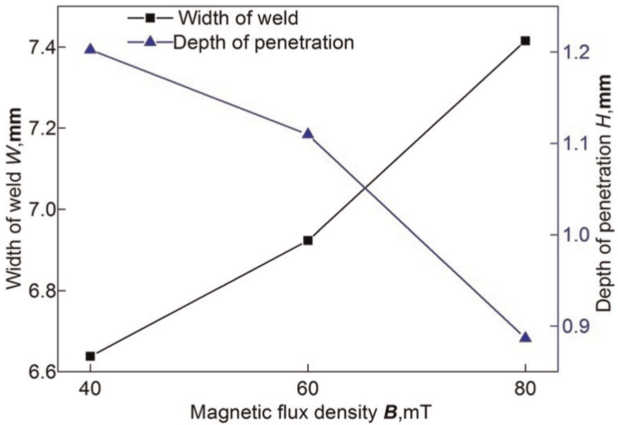
Effect of the magnetic strength on weld width and penetration.
Conclusion
A magnetizer is developed to exert external magnetic field in weld pool during high-speed GMAW. It is found that the added electromagnetic force is able to change the flow conditions of molten metal and lower the momentum of backward flow jet in the weld pool, so that humping bead is suppressed.
Both the arc and the weld pool are observed by a vision sensor under the conditions with and without the actions of external magnetic field. With the action of external magnetic field, the forward tilted arc axis and droplet transfer as well as the forward electromagnetic force in weld pool combine together to form a thicker layer of molten metal in the front part of the weld pool, while the accumulation of the molten metal at the pool rear does not occur and no hump is found to form.
There exists an optimum range of the external magnetic strength for obtaining good quality of weld beads. For the study case, satisfactory weld bead without humping and undercutting is obtained when the magnetic strength is 60 mT at a welding speed of 2.01 m/min. However, the external magnetic field causes some spatter, and the investigation is still ongoing to avoid this side effect.
Footnotes
Declaration of Conflicting Interests
The author(s) declared no potential conflicts of interest with respect to the research, authorship, and/or publication of this article.
Funding
The author(s) disclosed receipt of the following financial support for the research, authorship, and/or publication of this article: This research received the financial support from the National Natural Science Foundation of China (Grant No. 51275276) and the Research Fund for the Doctoral Program of Higher Education of China (No. 20120131130009).