
Abstract
This article aims at the development of sheet hydroforming for making an aluminum automobile fuel tank which is originally made by steel. Finite element model, including punch, blank, blank holder, binder and die cavity, is established in the first place. A commercial code LS-DYNA is used to simulate the forming process. Simulations are performed to investigate the design parameters, such as pressure, holding force, punch feeding and geometry of blank trimming, which are used for the experiment of prototyping. The prototypes of aluminum fuel tank are then fabricated and used to validate the simulation results. The experimental results show that simulations successfully predict the geometry, size, thickness distributions and location of maximum thinning ratio of aluminum fuel tank using sheet hydroforming.
Introduction
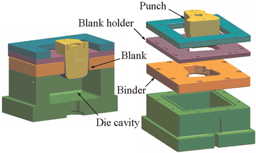
Sheet hydroforming (SHF), sometimes called hydromechanical deep drawing (HDD), is a metal forming technology which can be traced back to Second World War. 1 It has been widely adopted for making metal sheet components in automotive, aerospace, electronic and kitchen industries. Compared with conventional deep drawing, the main feature of SHF is to replace the female die by hydraulic pressure. Basically, SHF includes some key parts, that is, punch, blank holder, binder and die cavity as shown in Figure 1. In SHF process, undeformed metal sheet, called blank or workpiece, is first placed in the top of binder. The die cavity is filled with working liquid. Blank holder is used to clamp the blank associated with a binder. An O-ring may be introduced between the blank and the binder to prevent the leakage of working liquid so that the pressure in the die cavity can be upheld during the forming process. Punch is then moved toward the blank, and a gap between the punch and the blank is sometime required for the pre-bulging of the blank. Working pressure in die cavity is raised to slightly pre-bulge the blank in contact with the punch. The punch is subsequently fed to push the blank into the die cavity. During the forming process, working pressure should be kept high enough to press the blank to envelop the punch tight. Consequently, SHF may produce components with certain advantages, 1 that is, higher limit drawing ratio (LDR), better surface quality, less wrinkling, more uniform thickness distribution, less drawing operation, higher dimensional accuracy of the formed part and more complicated parts can be formed. However, the main drawback of SHF is that a higher drawing force and a higher blank-holding force are needed in comparison with those of conventional deep drawing. 1 In general, the challenges of using SHF lie in how to prevent overthinning, tearing and wrinkling of blank during the forming. The key parameters, including blank geometry, holding force, punch stroke, working pressure, curvature of die corner, lubrication between blank and die, are to be designed for the individual product using SHF. Lang et al. 2 have made a detailed review for the recent development of SHF technology.
CAD of SHF.
Siegert et al. 3 pointed out that the pre-bulging of the blank has the advantage of producing a work hardening in the middle of the part. This is useful in flat parts to produce stiffer and more geometrically accurate products with more hardness, which is better in dynamic denting. It can also be useful to have a pre-bulging in order to get more sheet metal into the die cavity when drawing deep parts.
Lang et al. 4 investigated the effects of pre-bulging pressure and pre-bulging height on the blank during the HDD of circular cups. In their study, the pre-bulging can make the sheet cover the punch nose earlier so that the caused friction between the blank and the punch can effectively prevent fracture at the initial stage of forming. However, if too large, pre-bulging height may cause serious bending and unbending effect and lead to fracture. They also indicate that the increase in punch head roughness may significantly increase the drawing ratio. 5
Swadesh et al. 6 proposed a modified die to improve the wrinkling of deeper cup using HDD. They indicated that the pre-bulging and the radius of die curvature are critical to tearing and wrinkling, respectively.
Önder and Tekkaya 7 studied the optimum forming process and process parameters of sheet metal for various cross-sectional workpieces, that is, circle, ellipses, rectangular and squares, by using three forming processes, that is, high-pressure sheet metal forming, HDD and conventional deep drawing. Their study revealed that HDD delivers less thinning than the conventional process, whereas the high-pressure sheet metal forming yields the largest thinning of the sheet for the same product geometry. Under the same drawing ratio, forming the workpiece with square cross section will yield more thinning than those of forming rectangular, ellipse and circle workpieces by using HDD. Apparently, the geometry and dimensional properties of workpiece are critical to obtain more satisfactory products.
Hama et al. 8 investigated the production of an elliptical steel cup using SHF. Finite element method (FEM) is used to study the formability prior to the experiment. The experimental validation confirms that SHF produces elliptical cup with much smaller thinning in comparison with the conventional deep drawing. Besides, the blank thickness at the punch shoulder is dramatically decreased, while that at the punch bottom is small. The blank thickness along the wall is first decreased and then increased from the punch shoulder to the flange. The blank thinning close to punch shoulder is due to stretch caused by friction between the punch and the blank. However, the blank thickening close to flange is due to material accumulation caused by material flow from blank holder into die cavity. In fact, the initial geometry and dimension of blank will significantly affect the material flow during the forming. Adequate trimming for the rectangular blank may be required for forming a circle cup using SHF.
Lang et al. 9 studied the HDD of square cups by using square punch and round die. Many advantages, such as improvement of drawing ratio, easy positioning of the tooling and the part can be formed accurately, are claimed in this approach. They also indicated that the effect of anisotropic properties of the sheet and the positioning of the blank will affect the forming process greatly. Besides, the evident wrinkling occurs at the side walls, though it is close to the transited corner of the flange. This may be attributed to the round die and could be the problem of forming a cup with low drawing ratio. The parameters of SHF process could be optimized through the theoretical analysis or simulation for making the products with simple geometry such as circle and square cups.9,10 However, they are still to be investigated for making the products with very complex geometry.
Failure prediction is of concern in the simulation of hydroforming. In general, forming limit diagram (FLD) is adopted for the investigation of blank fracture.7,9 However, the generation of FLD requires a large number of experiments since it involves very complicated behaviors of material plasticity such as anisotropic properties in multiaxial loading. Besides, modification of FLD is sometime required due to the stress triaxiality of blank in SHF. Liu et al. 11 investigated through-thickness normal stress induced by liquid pressure during the HDD of a cylindrical cup. They indicate that the stress states of non-free bulging zones, such as cup flange, cup wall and cup bottom, are away from plane stress. Thus, FLD may not be so effective for industry; however, blank thinning ratio has been used as the failure prediction of hydroforming instead.
The above researches provide us essential concepts and fundamental theories to process the SHF, although their products have comparatively simple geometry. For making products with complex geometry, the versatility of forming design can still base on these rules.
Parsa and Darbandi 12 investigated the SHF of making automobile body part, shell fender, by assessing two possible manufacturing procedures, that is, pure stretching and draw-in, which are different in boundary constraint of the periphery of initial blank. In their concluding results, the advantage of draw-in over pure stretching procedure has been obtained from thickness distribution. Optimum initial shape and size of the blank are critical to the formability of making such a product with complex geometry.
Kim et al. 13 proposed a novel method of multistage hydroforming process for making an oil pan by controlling the punch stroke backward. This method successfully improves the formability of making an oil pan which bursts by using single-stage hydroforming process.
Kang et al. 14 compared the production of an automobile fuel tank by using SHF and conventional stamping. In their approach, rubber bladder is used to replace the female die and to contain the pressurized medium. During the hydroforming process, the blank is formed inside the die by increasing the pressure in the working fluid that is contained in the rubber bladder. The simulated results show that SHF can produce a fuel tank with a more uniform and sound thickness distribution than the stamping operation.
The objective of this study is to develop SHF for making an automotive aluminum fuel tank which was originally made from steel using conventional deep drawing. The fuel tank consists of two parts. The upper part has much more complex geometry and higher forming height than those of the lower part. Thus, only upper part is investigated in this article. FEM is adopted for the simulation of forming process to obtain the loading conditions, that is, working pressure, holding force, punch feeding, friction force, and the blank trimming. Experiment of SHF is then performed to fabricate the prototype of fuel tank. The profile dimension and thickness distribution are measured to validate the simulation results.
Simulation of SHF
Finite element modeling
Figure 2 shows the finite element models of the upper part of fuel tank. The punch exhibits kind of complex geometry. Thus, the simulation is beneficial to understand the situation of loading and forming process prior to the experiment of prototyping. A commercial code LS-DYNA is adopted for the simulation in this study. Blank is molded using shell element. The punch and the binder are modeled using rigid shell since their deformations are allowed during the forming process.
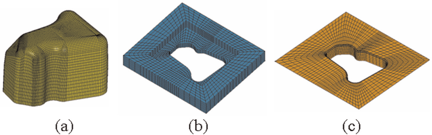
Finite element model of SHF: (a) punch, (b) blank holder and (c) binder.
The modeling of blank holding is critical to the simulation of SHF. The contact behavior between blank and blank holder significantly affects the formability of workpiece during SHF. To simulate such a complicated behavior, blank holder is usually modeled using rigid element when the commercial code of finite element analysis (FEA) is used. 11 Holding force is regarded as a constant and applied to the rigid blank holder. Jung et al. 15 indicated that blank-holding force should be distributed as a function of thickness over each node in the flange in the simulation of deep drawing of sheet. In their approach, rigid-plastic FEM considering planar anisotropy is used rather than modeling blank holder.
In this study, blank holder is modeled using elastic solid which provides more flexibility to simulate the contact behavior during the forming process. Distributed pressure is applied to the blank holder to generate holding force. The automatic contact of surface to surface is adopted for all contact conditions among the punch, blank, blank holder and binder. Coulomb friction law is assumed for the simulation among the punch, blank, blank holder and binder. A friction coefficient of 0.1 is assigned for the interfaces between the punch and the blank and 0.02 is for the interfaces among the blank, the blank holder and binder. 4
The effect of blank trimming on the formability is critical to SHF. Proper blank trimming can significantly reduce the material accumulation and facilitate the blank flow into die cavity. In this study, the blanks with and without trim are investigated.
Loading conditions, including working pressure, punch stroke and holding force, are the key parameters of SHF. Constant pressure is uniformly applied to the blank on the area enclosed by O-ring. The blank flows into this area should be automatically subjected to uniform pressure. Punch stroke is proportionally increased from 0 to 74 mm, which is the objective forming height of the fuel tank.
Material plasticity model
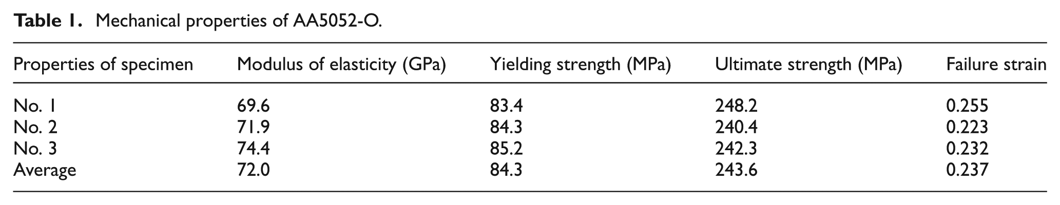
Aluminum alloys, AA5052-O and AA3003-O, are used for this study. The blank thicknesses of AA5052-O and AA3003-O are 1.6 and 1.2 mm, respectively. In general, power law is adopted for modeling the plasticity of stress–strain curve of the material.4,5,8,9 In this study, piece linear plasticity model is adopted for modeling the full true stress–strain curve obtained from the tensile test. The advantage of using this plasticity model is that tested stress–strain curve is considered into the simulation. Figure 3 shows the true stress–strain curves of AA5052-O and AA3003-O, and their mechanical properties are listed in Tables 1 and 2, respectively. Apparently, the material properties of AA5052-O exhibit higher strength but lower ductility than those of in AA3003-O.
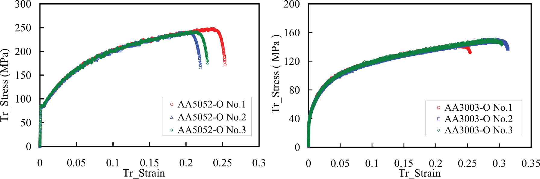
Stress–strain curves: (a) AA5052-O and (b) AA3003-O.
Mechanical properties of AA5052-O.
Mechanical properties of AA3003-O.
The mechanical properties of AA5052-O and AA3003-O blanks are simplified as isotropic since the blanks have been subjected to heat treatment of annealing which can increase ductility, soften material, relieve internal stresses, refine the microstructure by making it homogeneous and improve cold working properties.
Blank thinning ratio is adopted for the prediction of failure during the forming process since it can be directly measured and eventually validated from the experiment. The allowable blank thinning ratio is not allowed to over the 80% of average tested failure strain in this study. Thus, the allowable thinning ratios of AA5052-O and AA3003-O are 19% and 24%, respectively.
Simulation of SHF
Simulation is performed to investigate the proper loading conditions and the optimal geometry of trimmed blank in the first place. Figure 4 shows the simulation of a 30-mm forming high of AA5052-O blank with and without trimming. In this case, the holding force is 30 kN while the working pressure is 3 MPa. The maximum ratios of blank thinning are 22.1% and 18.8% for trimmed blank and untrimmed blank, respectively. Apparently, the trimmed blank provides more formability and less restraint of material flow during the forming process. In fact, the material flow during the forming process can be seen from the simulations. The untrimmed rectangular blank exhibits contractions at the middle part of the edge in three sides. In other words, material flow is restrained at the four corners of the rectangular blank. The same phenomenon is also found in previous research. 8
Simulation using (a) untrimmed and (b) trimmed blanks.
Figure 5 shows the simulation of partial forming of 30 mm high of AA5052-O using different blank holder models. In this case, the holding force is 18 kN which is insufficient to hold the blank well. When rigid shell model is used for blank holder, no wrinkling occurs at the blank fringe and the maximum ratio of blank thinning is about 19% as shown in Figure 5(a). However, when elastic solid model is used for the blank holder, wrinkling occurs around the blank fringe and the maximum ratio of blank thinning is 18.1% as shown in Figure 5(b). Apparently, elastic solid model provides more convincing simulation than rigid model in the contact behavior between the blank and the blank holder. The shortage of holding force can also be seen through the simulation of slight separation between the blank and the blank holder. However, this phenomenon is not found by using rigid shell model of blank holder. The wrinkling around the blank fringe implies that the leakage of working liquid may occur and working pressure may significantly drop in the test. When the holding force is increased to 30 kN, wrinkling around the blank fringe is smoothed as shown in Figure 4(b).
Simulation using different models of blank holder: (a) rigid shell and (b) elastic solid.
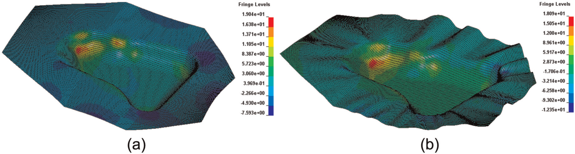
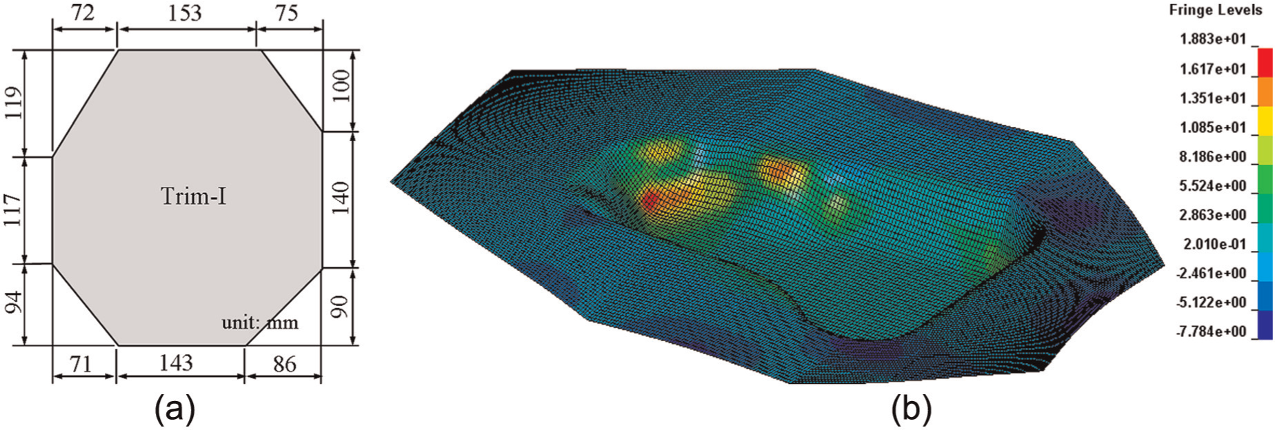
The different types of AA5052-O blank trimming are further investigated. Figures 6 and 7 show the simulations using two types of blank trimming, respectively. Using trim-I blank, the maximum ratio of blank thinning is 19% as the punch stroke reaches 30-mm high. Using the same loading condition, trim-II blank reaches the same maximum ratio of blank thinning 19% while the punch stroke reaches up to 46 mm high. Compared to trim-I blank, trim-II blank is trimmed off more materials at four corners. Apparently, the formability of blank using trim-II is better than that of by using trim-I.
Simulation using trim-I blank: (a) trim-I blank and (b) forming to 30-mm high.
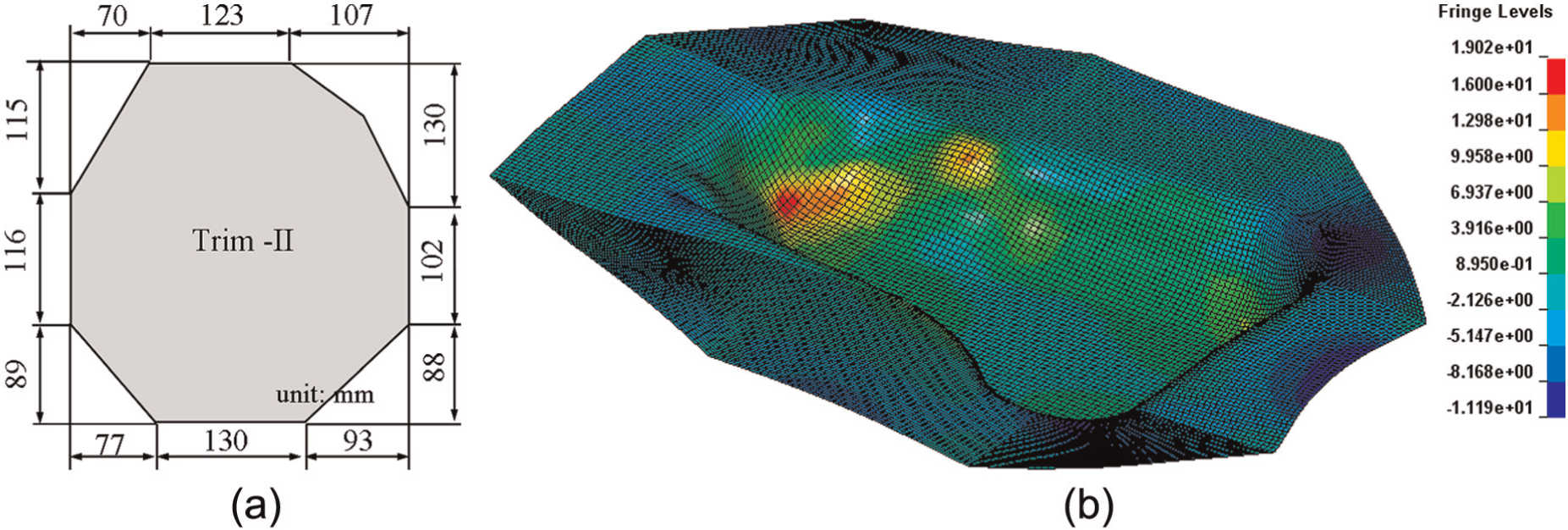
Simulation using trim-II blank: (a) trim-II blank and (b) forming to 46-mm high.
However, even though the forming high of trim-II blank is increased to 46 mm, the maximum blank thinning ratio of 19% is almost over allowable thinning ratio. Fracture may occur around the thinning area. Thus, the formability of blank is still to be improved. Two potential approaches may be adopted. One is to change the loading conditions, and the other is to modify the geometry of die or blank trimming. The increase in working pressure in die cavity will also request the increase in holding force; moreover, the increase in holding force will restrain the material flow of blank during the forming process. Thus, the modifications of die and blank trimming are adopted for this study. Figure 8(a) shows that trim-III blank removed more materials at its four corners in comparison with trim-I and trim-II blanks. Besides, Figure 8(b) shows that the radius around the edge of the binder is modified from 5 to 10 mm in order to facilitate the blank flowing into the die cavity during the forming.
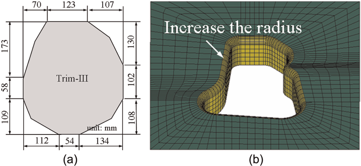
Modification of FEMs: (a) trim-III blank and (b) binder.
Figure 9 shows the simulation of SHF of AA5052-O using modified FEM. The maximum ratios of blank thinning are significantly reduced, that is, 14.1%, as shown in Figure 9(a), and forming height is increased up to 74 mm. Nevertheless, detachments are found at a-a and b-b sections, as shown in Figure 9(b), close to the areas of high thinning ratio of the blank. The detachment may cause the stretch of the blank and consequently lead to overthinning during the forming process. To improve this problem, the increase in working pressure in die cavity may be required. However, it is also required to increase the holding force which may restrain the material flow and also lead to the blank thinning.
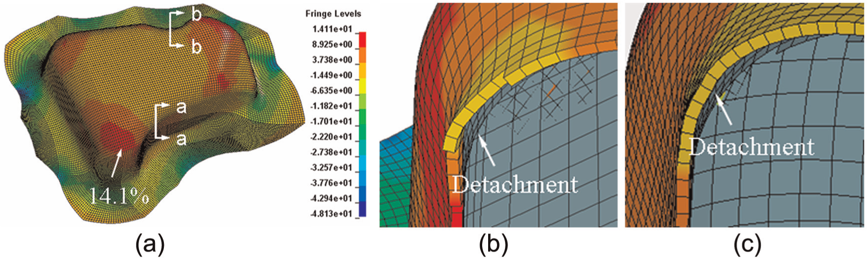
Simulation using modified FEM: (a) AA5052-O, (b) a-a section and (c) b-b section.
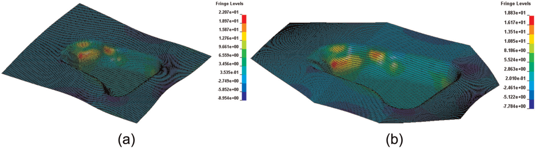
Figure 10 shows the simulation of SHF of AA3003-O using modified FEM. The maximum ratios of blank thinning are significantly reduced, that is, 13.8%, as shown in Figure 10(a), and forming height is increased up to 74 mm. However, detachments and wrinkling are found at the side wall, as shown in Figure 10(b), close to the area of high thinning ratio of the blank.
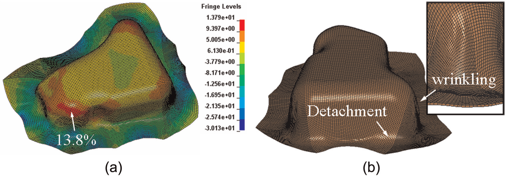
Simulation using modified FEM: (a) AA3003-O and (b) detachment and wrinkling.
Experimental validation
Experiment of SHF is performed to fabricate the prototype of fuel tank using a hydraulic machine. Figure 11 shows the prototyping of 30-mm forming height using improper design parameters. Figure 11(a) shows the untrimmed blank fractures around the area of maximum blank thinning. This phenomenon is also predicted from the simulation as shown in Figure 4(a). Figure 11(b) shows that the wrinkling occurs around the blank fringe under an insufficient holding force. This phenomenon is also predicted from the simulation as shown in Figure 4(b).
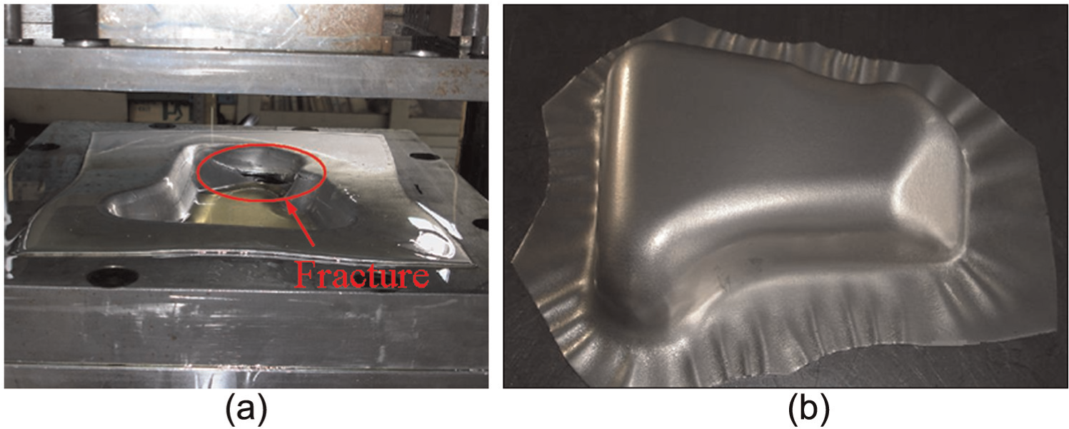
Prototypes using improper design parameters: (a) untrimmed blank and (b) insufficient holding force.
Figure 12 shows the prototypes of fuel tank of AA5052-O and AA3003-O using improved design parameters, such as trim-III blank, larger radius of binder edge and loading conditions. The working pressure in die cavity and the holding force are slightly increased to 3.2 MPa and 35 kN. The forming height successfully reaches 74 mm in each case. However, fracture occurs at the side wall close to the corner of AA5052-O prototype as shown in Figure 12(a). The contour of blank thinning ratio is also predicted from the simulation as shown in Figure 9(a). Maximum thinning ratio is located at the fracture line. No fracture occurs at the prototype of fuel tank using AA3003-O. However, significant wrinkling is found at the side wall close to the corner of blank fringe as shown in Figure 12(b).
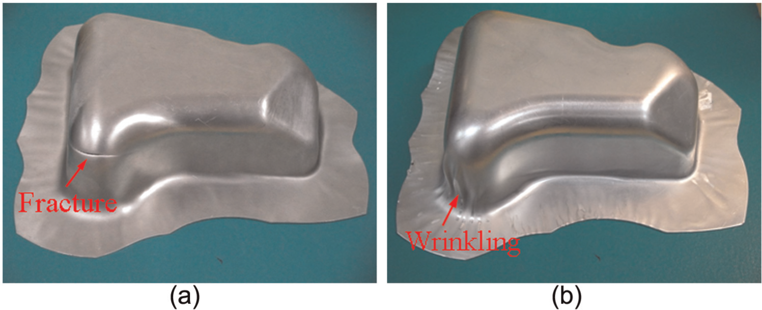
Prototypes using improved design parameter: (a) AA5052-O and (b) AA3003-O.
The thickness of fuel tanks is measured using an ultrasonic machine (Olympus-38DL PLUS). Four lines, that is, A, B, C and D, are measured from the top surface to the bottom fringe of the fuel tank and used to compare with the simulations.
Figure 13 shows the thickness distributions obtained from the two prototypes of AA5052-O and its simulation, respectively. Along line-A, the correlation between experiment and simulation is relatively good except for the section around the bottom corner as shown in Figure 13(a). The abrupt change in geometry from the slope to the bottom corner of fringe may cause the deviation of thickness measurement. Along line-B and line-C, the correlations are also good as shown in Figure 13(b) and (c). Along line-D, the correlation is fair except for the section around the fracture line as shown in Figure 13(d). The test data of blank thickness close to fracture line abruptly drop. The thinning ratios measured from prototype-1 and prototype-2 are 24% and 19% respectively. However, in the simulation, overthinning is not found even though its maximum thinning ratio is close to the fracture line. It may be attributed to the shortage of shell element in simulating the local contraction of blank. Giagmouris et al. 16 suggested that solid elements are more accurate than shell elements in the simulation of the evolution of local thickness contractions and necking failure of a three-dimensional (3D) shell structure in the presence of normal contact stresses.
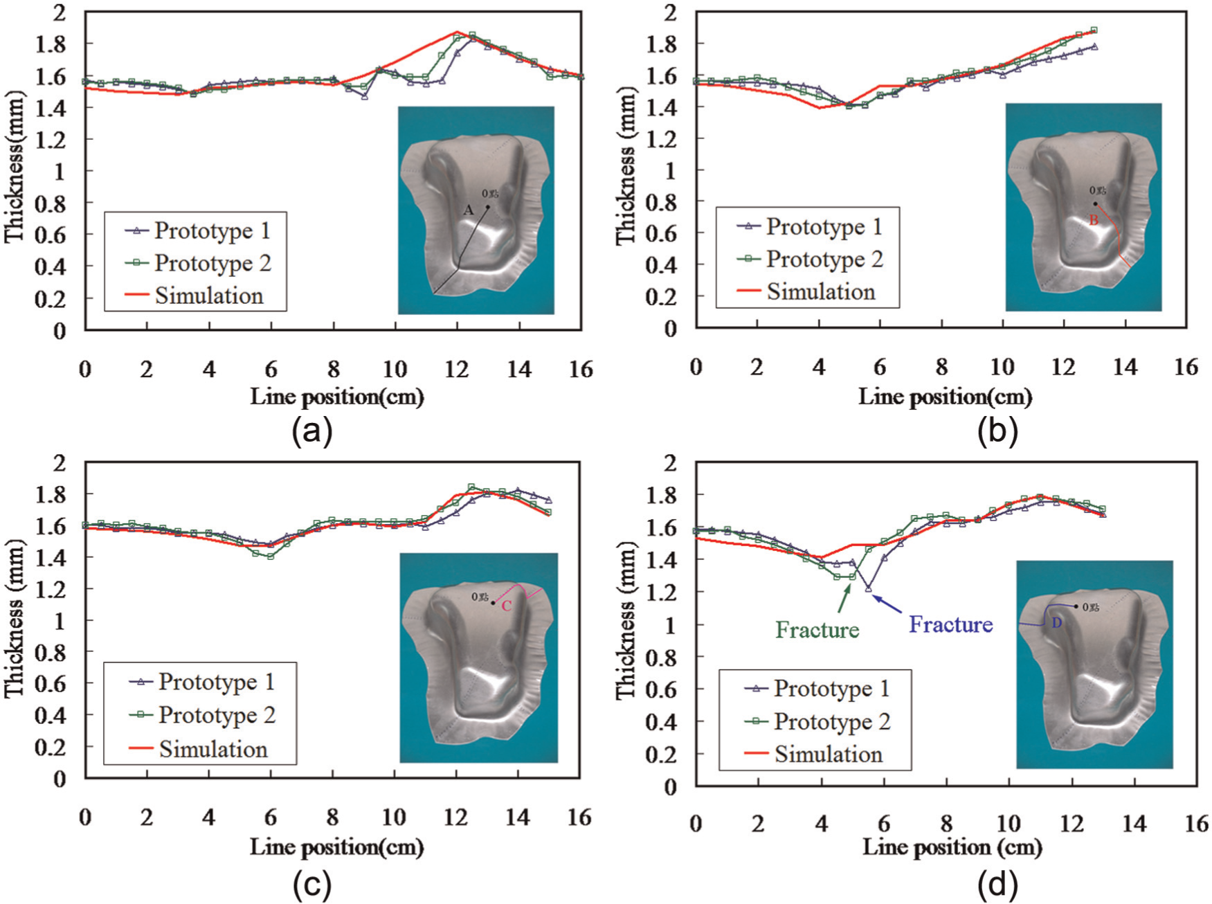
Comparison of thickness distribution of prototypes AA5052-O: (a) along line-A, (b) along line-B, (c) along line-C and (d) along line-D.
Figure 14 shows the thickness distributions obtained from the two prototypes of AA3003-O and its simulation, respectively. Along line-A, the correlation between experiment and simulation is relatively good except for the section around the bottom corner as shown in Figure 14(a). The phenomenon is similar to that in the fuel tanks of AA5052-O. The abrupt change in geometry from the slope to the bottom corner of fringe may cause the deviation of thickness measurement. Along line-B and line-C, the correlation between experiment and simulation is good as shown in Figure 14(b) and (c). There is no measurement along line-D since it is difficult to measure the thickness along the wrinkling area of fuel tank as shown in Figure 12(b).
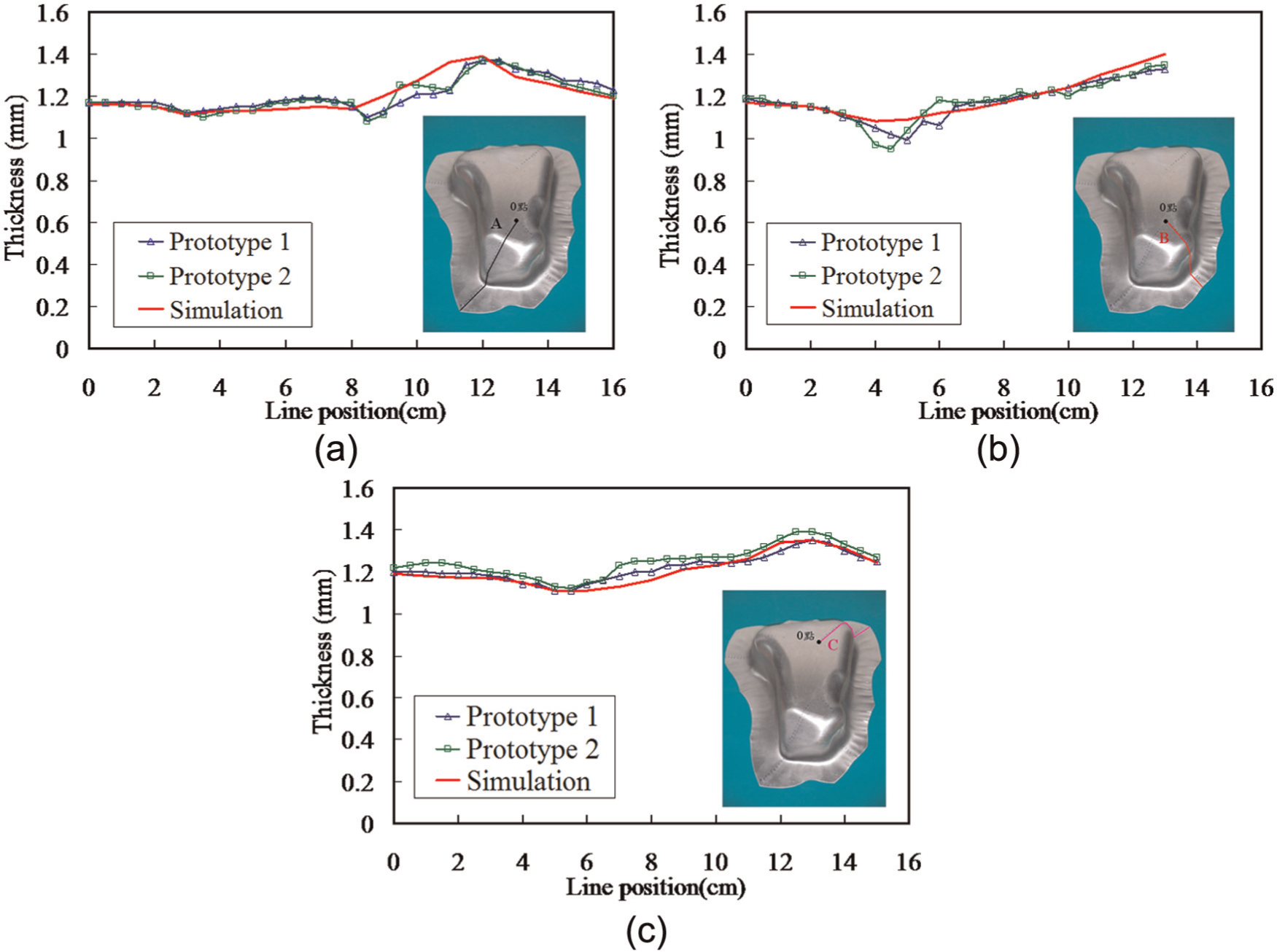
Comparison of thickness distribution of prototypes AA3003-O: (a) along line-A, (b) along line-B and (c) along line-C.
Conclusion
The development of SHF for fabricating an automobile fuel tank using aluminum alloys has been studied. Simulation using FEA provides the reliable prediction of formability of blank and the relevant design parameters prior to the prototype fabrication. These design parameters, such as loading conditions and blank trimming, significantly save the try out cost of prototype fabrication.
The geometry of blank trimming is critical to the formability of fuel tank especially for such a complicated geometry product. Simulation shows that the formability is improved if more materials at the four corners of rectangular blank are properly trimmed off.
The experimental results show that the fabrication of fuel tank using AA5052-O is still not reliable. Fracture occurs at the side wall around the corner during the forming process. It is due to the insufficiency of working pressure since detachments are found between the tank inner and punch around this area in the simulation. This may lead to overstretch in blank caused by punch feeding. To improve this problem, the increase in working pressure in die cavity may be required. However, it will also increase the holding force which may restrain the material flow of the blank during the forming process.
The experimental results show that the fabrication of fuel tank using AA3003-O has been successfully accomplished. However, wrinkling occurs at the side wall around the corner of fuel tank. The wrinkling and detachment are also predicted from the simulation. Apparently, the current loading conditions are still not optimal and to be improved for further prototype fabrication.
The future work lies in the optimization of loading conditions. For instance, the multistage control of working pressure and holding force may be required for fabricating this fuel tank.
Footnotes
Declaration of conflicting interests
The authors declare that there is no conflict of interest.
Funding
The authors would like to acknowledge the support of Taiwan Ministry of Education to this research through grant number 100M-06-022.