
Abstract
In this experimental research, the electrode caps are investigated for deterioration under the resistance spot welding technology. The research was fundamentally conducted using two different electrode actuation systems to understand the wear and tear factors of electrode caps. A Japanese model 75 kVA pedestal, alternating current waveform of spot welder, was engaged to carry out the welding processes up to 900 welding attempts on pneumatic system. Subsequently, it was converted into servo-based electrode actuating systems and repeated the entire welding processes. The carbon and stainless steel sheets are primarily used to weld in this experiment. The electrode caps are then sharpened by CDK-R dresser to remove the mushroom growth which has regularly been induced for every 400 welding attempts. As for the macrograph and micrograph observations, the electrode caps are measured for diameter growth of electrode caps as well as the copper-to-chromium ratio. The chromium content has been significantly reduced at the electro tip areas due to the direct expose of heat generation which becomes a regular phenomenon in both the systems. However, the results from servo-based system are deemed to be offering lower tendency of wear and tear factors when compared to the pneumatic-based system.
Introduction
A pure copper is naturally soft, has very low tendency of corrosive effect and fails prematurely in demanding applications. 1 However, it can be strengthened by various methodologies including, but not limited to, alloying, precipitation hardening, cold work, solid solution and dispersion strengthening. 2 A mixture of copper alloys is a good choice for the manufacturing of spot welding electrode caps due to its physical properties. As such, most of the welding experts often prefer to use the copper alloys which contain substances such as chromium, beryllium, zirconium and the like for resistance spot welding (RSW) application. 3 Figure 1 shows the copper and chromium phase diagram for copper-based alloys as this research uses such combination of electrodes. 5 It shows that chromium is easily soluble in the liquidus of copper when heated above 1076 °C and below 1860 °C. Once solidified, it requires equal amount of heat to re-melt it again completely. Hence, this factor gives drawback on the copper–chromium alloy to handle the carbon and stainless steel welding process, because the carbon steel melting point falls between 1426 °C and 1539 °C, whereas the stainless steel melting point falls between 1400 °C and 1450 °C. 4 The copper and chromium solubility phases are actually of the eutectic type. The face-centered cubic (FCC) will be formed in copper, whereas body-centered cubic (BCC) will be formed in chromium when solidification process is concerned in copper–chromium alloy.
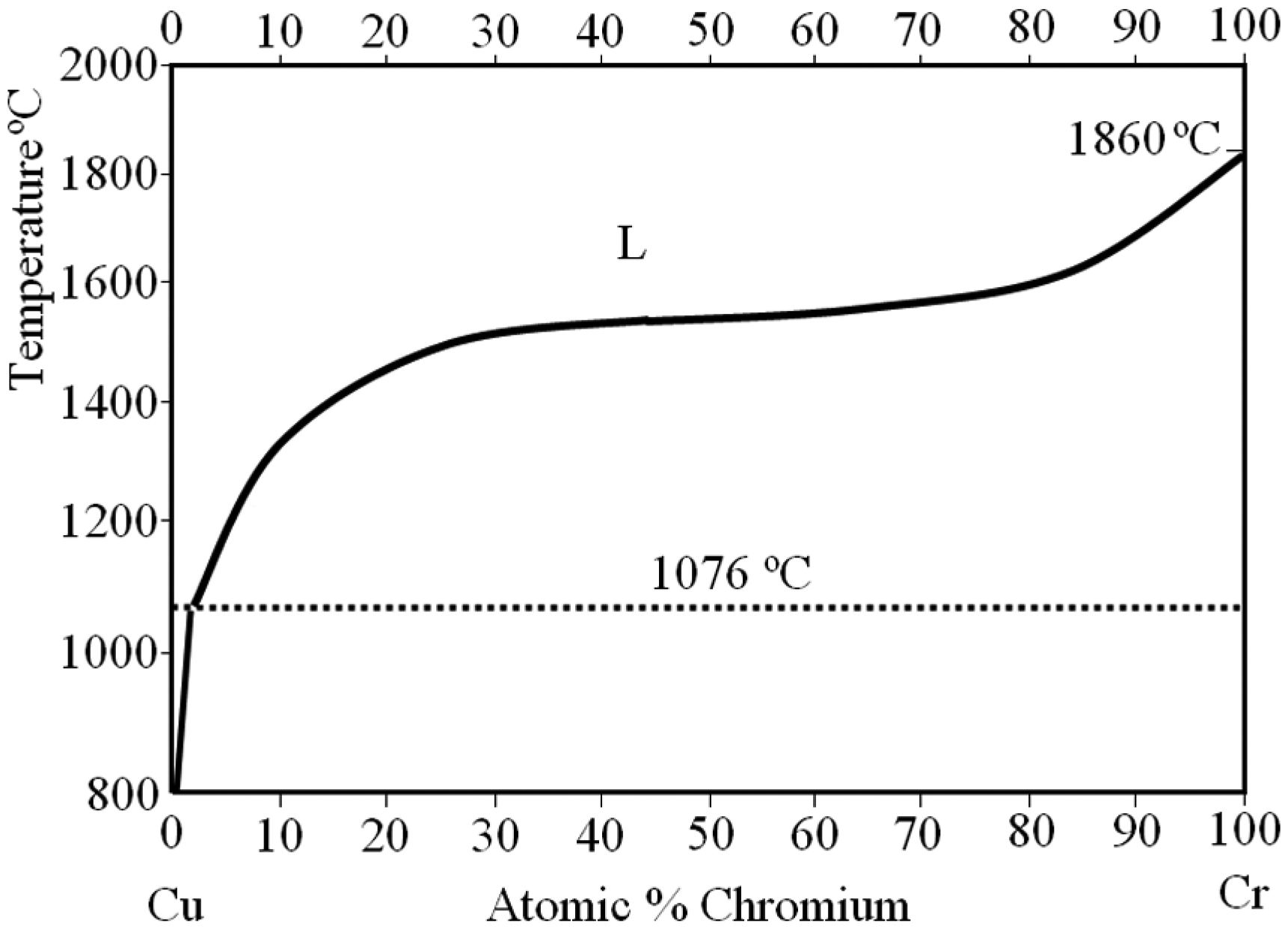
Copper and chromium phase diagram. 4
As the number of welding processes is repeatedly carried out on carbon and stainless steels, the mushrooming effect at the edge of electrodes grow in outward direction, enlarging the tip diameters apparently, as shown in Figure 2 for the surface in addition to the cross-sectional views.6,7 The electrode tip cleaning procedures are therefore carried out for every 400 welding attempts as to maintain the truncated shapes from the electrode tip with regard to mushroom growth. This is absolutely necessary to avoid any drastic changes in resistive components due to the imbalanced surfaces or enlarged contact points between electrodes to sheets or vice versa.8 –10 The mushrooms grown for every 400 welding attempts are therefore well cleaned using dresser, so almost an acceptable flat surface is retained throughout the entire welding process. However, the electrode compressing mechanism is certainly subjected to the consistencies of force profiles that are supplied during welding process in RSW. 11 So, the two different compressing mechanisms are inspected for wear and tear factors of electrodes. In this research, around 900 welding attempts were carried out for two dissimilar types of electrode actuation systems to characterize the welding performance.
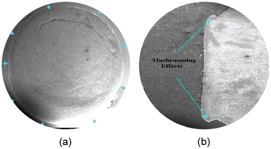
Mushroom growth of electrodes due to deterioration: (a) top view and (b) cross-sectional view.
Experiment
The carbon and austenitic stainless steels were prepared in a rectangular shape as follows: the length of specimen, 200 mm; the width, 25 mm and two thicknesses, 1 and 2 mm, as exactly shown in Figure 3. Two pairs of water-cooled copper–chromium electrodes with 30° truncated round tips (5 mm in diameter) were used to accomplish the entire welding processes. The test samples were initially welded with pneumatically controlled 75-kVA alternating current (AC) waveform system, and later, the electrode actuation was mechanically converted to servo-assisted system with similar electrical specification. With such arrangement, around 900 welding attempts were carried out for each system to understand the electrode’s wear and tear factors. The committed electrode caps are subsequently analyzed for deterioration and also checked for the internal micro- and macrostructural orientation. It should be noted here that the Class 2 spot welding electrodes are made of copper and chromium chemical elements, according to the Resistance Welding Manufacturing Association, America (RWMA) classification (Table 1).
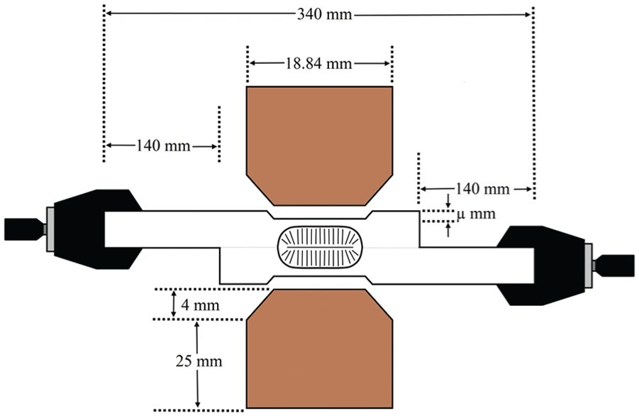
Alignment of electrodes and base metals.
RWMA Group “A” electrodes (Class 2 chromium–copper: C18200).
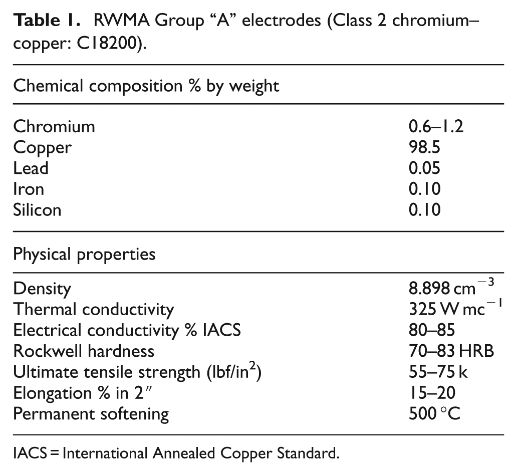
IACS = International Annealed Copper Standard.
Results and discussion
Electrode deformation in pneumatic-based system
The original size of electrode tip on both sides was just 5 mm in diameter, and it has been widened up to 7.458 mm (49% mushroomed) on upper electrode side and up to 7.238 mm (44%) on lower electrode side after accomplishing almost 900 weld attempts. The imbalanced deformation on both sides must not be interpreted as Peltier’s effects (high electrode deformation on anode side than cathode side in direct current (DC) spot welder) because of the very small percentage of deformation that took place at the tips (the difference is just about 5%). The electrode on upper side has slightly higher deformation rate due to the regular impact produced by the squeezing moment of electrode onto the base metals. On the same circumstance, the unmovable lower electrode has very smooth touch between electrodes to base metals as it was regularly handled by human hand.12,13 The base metals that occupied the top of lower electrode are gently handled by human hands before commencing any of the welding process; so, there is very minimized impact as a matter of fact.14,15 Figure 4 shows the macrograph of electrode tips for pneumatic-based system with which two types of dressing procedures were carried out to attain 900 welding attempts.
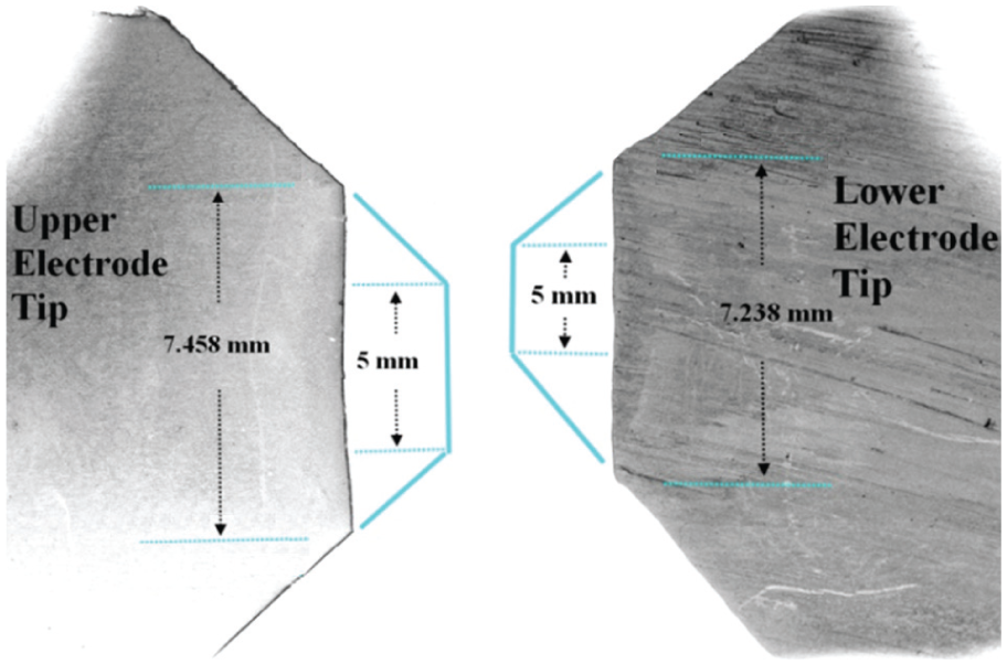
Electrodes’ macrograph views after accomplishing 900 welds (pneumatic-based system).
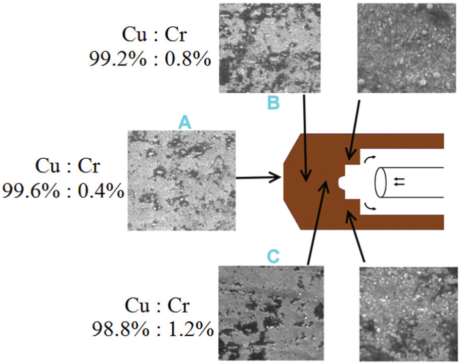
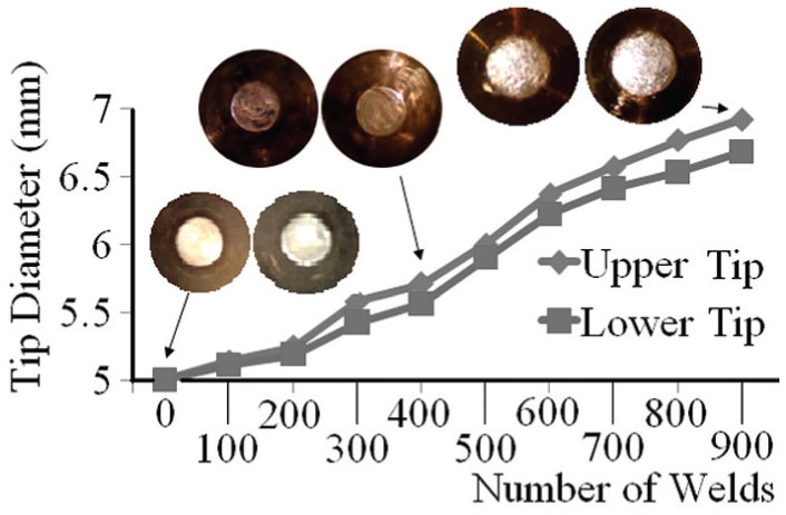
Having considered the vanishing factors of the electrode surfaces after accomplishing 900 weld trials, the electrodes are carefully scanned for internal structural changes. Point A in Figure 5 represents the upper electrode’s vertex at which the base metals’ molten heat (≈1600 °C) was directly exposed to. The microstructural views show that the chromium precipitation is higher at point A when compared to points B and C of the tip, so the degradation is relatively high. Moreover, the points B and C are the consecutive regions of electrode which is physically manufactured to connect with the electrode holder. So, the points B and C are also exposed to the thermal conduction (expansion rates) but not as how the tip has experienced to the thermal generation directly. The point B has moderately balanced amount of chromium-to-copper ratio, which is a middle portion between points A and C. However, the differential cooling rate at point C due to the internal water flow (2 L/min) has been avoiding the huge amount of chromium precipitation but somehow lead to severe internal cracks on the upper electrode side after accomplishing 900 welding attempts. In order to observe the diameter degradation, the growths of electrode tips’ diameter for every 100 weld attempts were recorded, and it is shown in Figure 6 for pneumatic-based system.
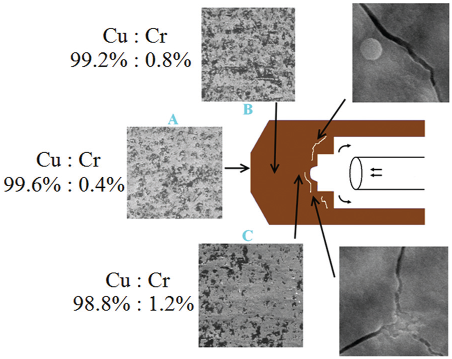
Upper electrode's microstructural views (pneumatic based system, % represents the atomic level) (welding and cutting).
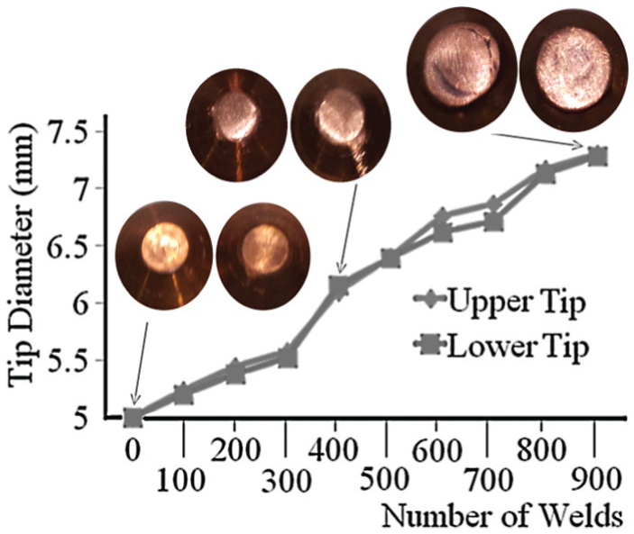
Changes in electrode tip due to mushrooming effects (pneumatic-based system) (welding and cutting).
Electrode deformation in servo-based system
Hitting the base metals during squeezing cycle is a major problem in pneumatic-based electrode actuating system, and it was clearly mentioned by previous researchers.16,17 This factor may reduce the lifespan of electrodes and also cause rapid mushroom growth at the edge of electrodes. 18 So, the electrodes involved in the welding process should be analyzed for both cases as it is subjected to slide or skid during squeezing process. 19 It is found that the servo-based system aligns well and protects the electrode tip geometry from the hitting effect due to smooth and fine touch when compared to the pneumatic-based system. 20 Although the electrode tips are frequently cleaned using conventional tip dressers for both the systems, the mushrooming effects still slightly enlarged the diameter of tips and resulted in contact resistance drop over time. Brand new electrode caps were replaced with 5 mm of diameter for the newly designed servo-based system, but it has been widened up after few hundred weld attempts as before. This time, it has been mushroomed to about 6.920 mm (38% mushroomed) on upper electrode side, whereas 6.679 mm (33%) on lower electrode side after accomplishing approximately 900 weld attempts (Figure 7) as how pneumatic-based system is initially experienced. The upper electrode is protected from vanishing itself by 11% (49%–38% = 11%), and the lower electrode is also protected from vanishing itself by 11% (44%–33% = 11%). Both electrodes almost simultaneously and approximately vanished. Whatsoever, there are no cracks noted for any of the electrodes that have been associated in the servo-based system even after 900 weld trials are performed. Figure 8 shows the upper electrode’s microstructural view of servo-based system. The chemical elements’ distribution of chromium to copper is seemingly to be almost same as that of the pneumatic-based system.
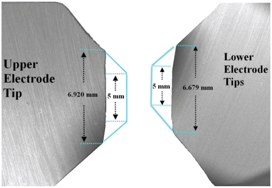
Electrode’s macrograph views after accomplishing 900 welds (servo-based system).
Upper electrode’s microstructural views (servo-based system, % represents the atomic level).
The diameter measurement of electrodes for every 100 weld attempts of servo-based system is shown in Figure 9. Almost flat types of surfaces (Figure 9) are noted for servo-based system when compared to the pneumatic-based system (Figure 6) after accomplishing few hundreds of welds.
Changes in electrode tip due to mushrooming effects (servo-based system).
Conclusion
The deterioration of electrode caps is unavoidable in RSW regardless of electrode actuation systems. However, some distinguishable outcome between two common electrode actuation systems in RSW can be categorized as follows:
A “one-time” electrode reshaping procedure is recommended for an average of 400 welding attempts with RWMA Class 2 copper–chromium electrode caps.
Two truncated round tip of electrode caps (originally 5 mm diameter) were enlarged up to 7.458 mm (49% mushroomed) on upper electrode side and up to 7.238 mm (44%) on lower electrode side after accomplishing almost 900 weld attempts in pneumatic-based electrode actuating system.
Similarly, another two truncated round tip of electrode caps (originally 5 mm diameter) were enlarged up to 6.920 mm (38% mushroomed) on upper electrode side and up to 6.679 mm (33%) on lower electrode side after accomplishing almost 900 weld attempts in servo-based electrode actuating system.
The upper electrode vanishing percentage is approximately reduced by 11% (49%–38% = 11%), and for the lower electrode, it was around 11% (44%–33% = 11%) in servo-based system, when both systems are relatively compared for deterioration.
The direct heat exposure to the electrode tips has obviously caused some chromium precipitation from solid phases of copper–chromium electrodes, no matter what the electrode actuation is.
Several internal cracks have been noted in electrode caps that are associated with pneumatic-based system.
Footnotes
Declaration of conflicting interests
The author(s) declared no potential conflicts of interest with respect to the research, authorship and/or publication of this article.
Funding
The author(s) received no financial support for the research, authorship and/or publication of this article.