
Abstract
Fixture error is one of the error sources in machining operations. Locator position inaccuracy and locator height error are the main sources of fixture error. The optimal positions of the locators are a critical problem for minimizing the geometrical and dimensional error of workpiece. This article proposes a genetic algorithm–based optimization method to arrive at a layout of locators for minimum machining error in 3-2-1 locating approach. The focus of this optimization is the positional tolerance of holes. So, a mathematical model of the hole position tolerance with respect to variation of locator position is developed. The planes of the workpiece actual coordinate system are mathematically modeled on the workpiece theoretical coordinate system. The capability of the proposed approach has been shown by using an example. The result shows that the proposed genetic algorithm method can be used to calculate locating errors and find the optimal locating layout within the specified tolerance range, which is critical for fixture design in hole-making process.
Introduction
Fixture locator error causes the incorrect positioning of the workpiece in the fixture and inaccuracy in machined surfaces. Moreover, inaccuracies in locators’ layout result in a deviation of the workpiece from its nominal specified geometry. For a part to be acceptable, this deviation must be within the limits allowed by the geometric tolerances specified. 1 The optimal layout of fixture elements could reduce the errors. Fixture layout design uses two models—one geometric and one kinetic—to represent, verify, and optimize locator layout. The geometric model is used to establish the relationship between workpiece and fixture displacements, and the kinetic model is used to link external forces with fixture deformation and workpiece displacement. 2 In the recent years, many researchers have studied the fixture layout design with respect to above models. Most of the researchers used kinetic model to optimize the fixture layout. The main objective in these optimization problems was to minimize workpiece deflection caused by clamping and cutting forces. This type of optimization was complicated and time-consuming and was only used for two-dimensional (2D) models or simple cubic three-dimensional (3D) models because of the linking between a finite element solver such as Abaqus and an optimization software such as MATLAB. In addition, the output of the optimization could not be used for satisfying a geometric tolerance directly. Menassa and DeVries, 3 Li and Melkote, 4 Amaral et al., 5 Kaya 6 and Raghu and Melkote 7 are some of the researchers who have studied in this field.
In contrast to using kinetic model for the fixture design optimization, in the existing literature, a geometric model is used to study the effects of the locators’ height error on the inaccuracies created in position tolerance. In this article, the objective function is to reduce the position tolerance variations. The output of the optimization could determine whether the position tolerance is satisfied with the optimum locators’ layout or not. This method is simple and useful for tolerance analysis in hole-making process. Like this research, some of the researchers have used a geometric model to study the effects of fixture errors on the positioning accuracy of the workpiece. Asada and By 8 analyzed the problem of automatically locating fixture elements using robot manipulators. They developed a kinematic model that can be used to analyze the fixture layout, deterministic locating, accessibility and detachability, bilateral restraining, and total restraint. Huang and Gu 9 classified the machining errors in six categories and used the homogeneous transformation matrix (HTM) to model machine, fixture, and datum errors. Rong et al. 10 derived a mathematical definition to describe position, profile, and orientation tolerances, then influences of locating error were considered in 3-2-1, pin-hole and V-block locating approaches. Their work was based on homogeneous locating and orientation matrix. Wang 11 suggested an optimal approach to the locator configuration design for reducing geometric variations at the critical points of machined features. Cheragi et al. 12 presented a mathematical approach to study the effect of datum target point variation on part acceptance. It was found that datum target variation has a profound effect on the measured location of holes referencing those datums. Xiong et al. 13 developed a mapping model between the error space of locators, and the workpiece locating error space with the use of the Jacobian matrix. Given the geometric tolerances of locators, the calculating methods of the locating errors of the workpiece were developed for the deterministic localization, overdeterministic localization, and underdeterministic localization cases by using this mapping model. Qin et al. 14 developed a synthetic analysis to investigate the workpiece position error in fixture locating schemes. A general formulation of fixture modeling was proposed to establish the relationship between the workpiece position error and its source errors. The locating scheme was validated experimentally by means of a typical cylindrical workpiece. This mathematical model was useful for fixture error, but did not consider datum error. Wan et al. 15 announced that the machining accuracy of the workpiece depends on errors of machine tool, fixture, and datum. The objective of their article was to provide a framework for abstracting an error model that integrates these three types of errors into a unified one. The differential motion theory was used to build the evaluation model of the errors. Estrems et al. 16 introduced a method to analyze the fixture and workpiece inaccuracies and determine uncertainty and errors of the workpiece critical dimensions in the machining process. Using their method, it was possible only to predict whether the workpiece is acceptable or not. Ramesh et al. 17 reviewed the effect of geometric, cutting-force-induced, fixture-dependent, and thermal errors in machine tools and the methods for compensating these errors. Butt et al. 18 proposed a comprehensive analytical model of a 3-2-1 fixturing system, consisting of a kinematic and a mechanical part. The kinematic model relocates the initially misplaced workpiece in the machine reference through the axial advancements of six locators, taking all the fixturing elements to be rigid. The mechanical model calculated this displacement of the part, considering the locators and clamps to be elastic. Raghu and Melkote 19 presented a model that predicted the final position and orientation of a workpiece due to fixture geometric errors and fixture-workpiece compliance. The method incorporated the effects of fixture geometric errors, contact compliance, bulk compliance of the fixture-workpiece system, and contact geometry in the system to identify the final position and orientation of the part subject to clamping forces. The model was experimentally validated for specific cases involving a 3-2-1 fixture.
There have been no attempts made, to the authors’ knowledge, on the mathematical modeling and locator layout optimization based on reducing the position tolerance variations. This article deals with the influence of locator height error and locators’ layout on the compliance of geometric tolerances defined on the workpiece. A mathematical model is developed by using applied linear algebra in the first step. The model determines the influence of locator height error on hole position tolerance and defines the actual coordinate system. A genetic algorithm (GA) optimization approach is also used to minimize the error by changing the locator layout based on the proposed model in the next step. This method is simple and useful for tolerance analysis in hole-making process. The remainder of this article is organized as follows. Section “Effect of errors on workpiece localization (positioning)” explains the effect of errors on workpiece localization. The mathematical model for hole position error (HPE) has been presented in section “Problem formulation.” Section “Optimization of fixture layout using GA” describes the approach of GA method for fixture layout. Finally, the case study and conclusion are given in sections “Case study” and “Conclusion,” respectively.
Effect of errors on workpiece localization (positioning)
Errors of machine tools, fixture, and datum surface on workpiece to be machined influence the machining accuracy of the workpiece. Machine tool errors are due to geometric, kinematic, temperature, and cutting-force errors. There are several solutions for machine tool error compensation, but this is not within the scope of this article. Fixture-dependent errors are fixture setup, position of fixture elements, deformation of lift-of part, clamping intensity of workpiece, surface contact between workpiece and fixture, and so on. However, position of fixture elements and fixture setup (locator height error) have an effect on defining geometric model, and they are studied in this work. The third source of error, datum error, is due to the manufacturing error of the workpiece machining in previous setup. Figure 1 explains the effect of datum and fixture errors.
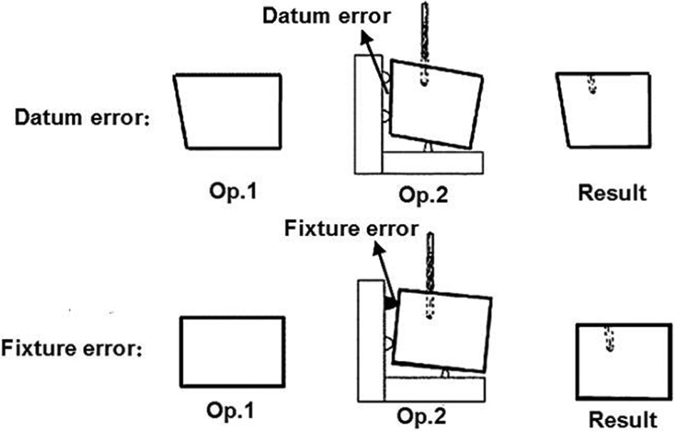
The effect of datum and fixture error.
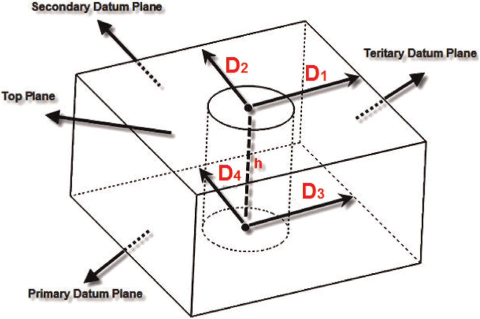
Fixture restricts the degrees of freedom (DOFs) of the workpiece in space. Each workpiece in space has six DOFs. Thus, the fixture should restrain all DOFs of the workpiece. These DOFs can be restrained by using six locators; each one restrains one DOF of the workpiece. A general 3-2-1 fixture layout shown in Figure 2 is a common method.
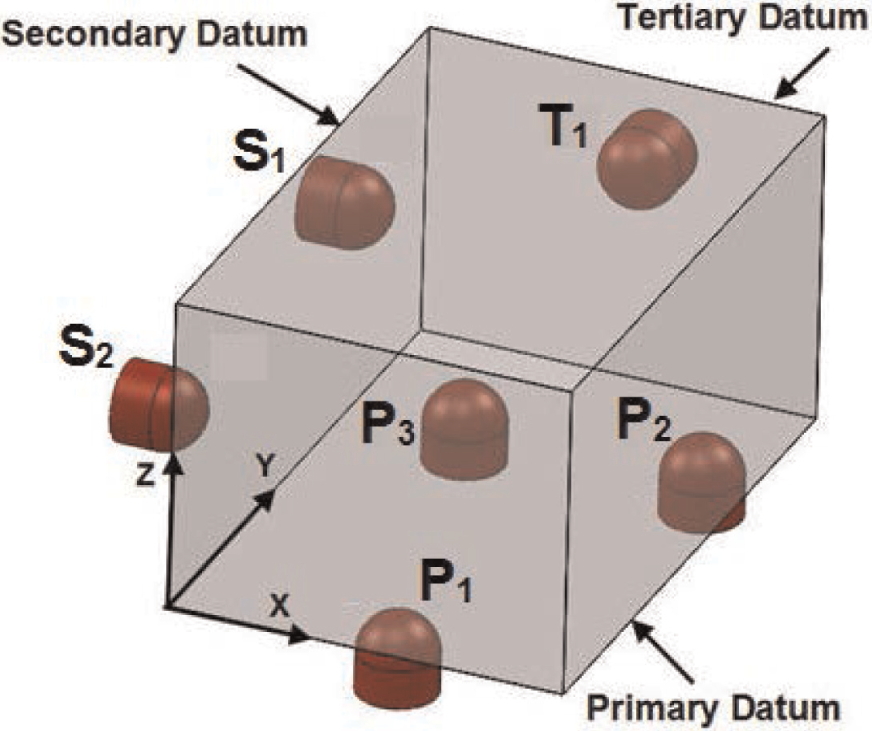
Configuration of datum planes and locators.
Part deviation error is mainly caused by setup and machining operations. During each operation, the part is fixed in a fixture and then cut in the machine tool. Three coordinate systems are introduced as references to describe the part deviation and operational errors: the machine coordinate system (MCS), in which the fixture is located and oriented on the machine table; the fixture coordinate system (FCS), on which the part is located and oriented; and the workpiece coordinate system (WCS), in which the part surfaces are represented. Figure 3 shows the MCS, FCS, and WCS.
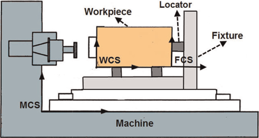
Fixture, machine, and workpiece coordinate systems.
Problem formulation
During machining, the tool path is defined with respect to the MCS. Ideally, the locators make point contact with the workpiece and the position and orientation of the datum reference with respect to the MCS, which is perfectly accurate. However, in reality, the geometry and position of the locators are imperfect, and the datum reference they produce has position and orientation errors with respect to taking machine reference frame into consideration. This misalignment produces geometrical errors in the features machined on the workpiece. The “position” geometrical tolerance defines a tolerance zone within which the center of the hole must be located. The definition of the “position” tolerance for cylindrical holes has been illustrated in Figure 4. The hole is located by considering one or more datums. The height or orientation error of each locator causes the tool path change and position error.
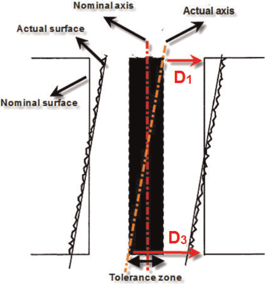
Illustration of a position tolerance.
Any variation or error in locators’ layout will show itself as variation or error in the measurement of the distance between the feature and the datum. The HPE is defined as the difference between the nominal hole position and the actual hole position. For example, in the part shown in Figure 5, the parameters of
Position error at the top and bottom surface.
To get the actual hole position, the equation of the datum planes needs to be derived first in terms of the locators’ position. The primary datum plane is defined by three locators.
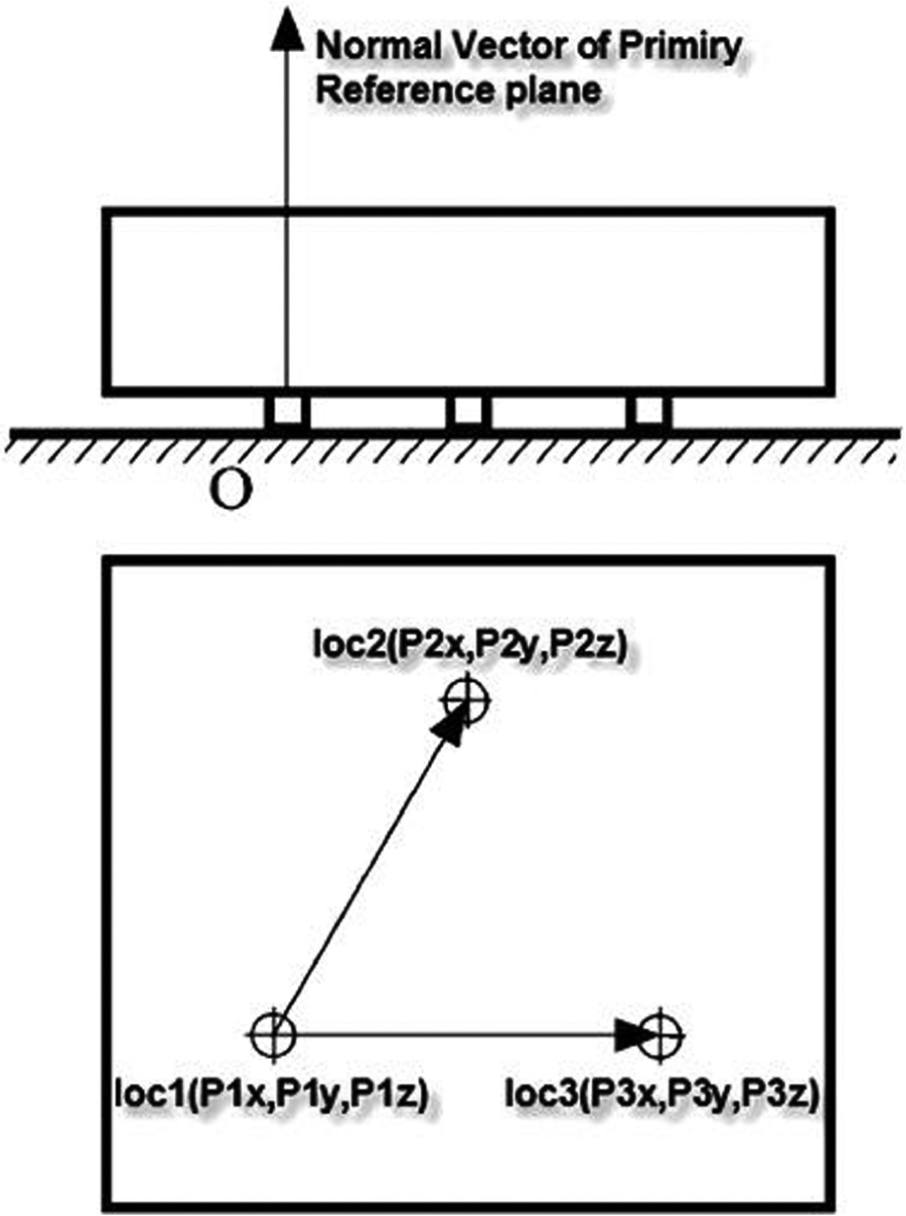
The primary datum plane.
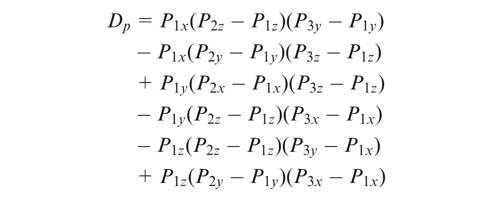
The equation for calculating the primary datum plane is shown in equation (1)

where


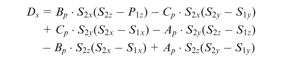
The secondary datum plane is defined by the coordinates of fourth and fifth locators and a vector that is normal to the primary datum plane and passes through fourth or fifth locators.

where


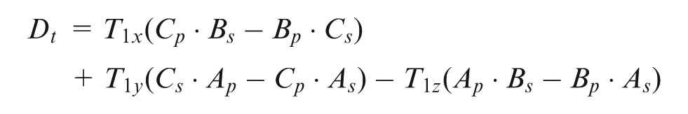
The tertiary datum plane is constructed using the position of sixth locator and two normal vectors on primary and secondary datum planes. The required relation for obtaining the tertiary plane is shown in equation (3)

where


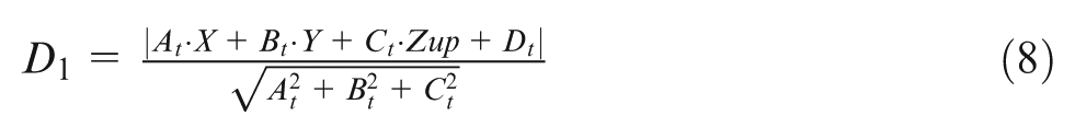
It is mentioned that the position error of the hole is the difference between the nominal hole position and the actual hole position. The actual position of the hole at the bottom plane, primary datum, can be expressed by the following equations
In these equations,
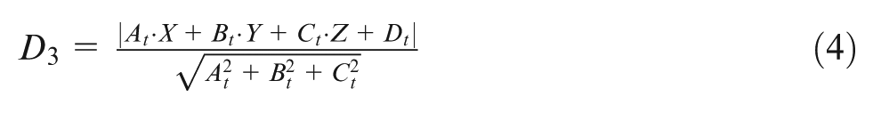
As shown in Figure 5, the distances of the actual position of the hole at the top plane with regard to the tertiary and secondary datum plane are

In the above equation, the Z coordinate of top plane is titled as
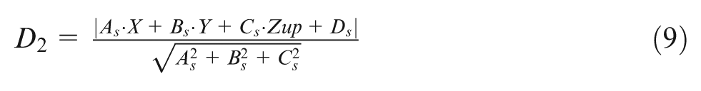
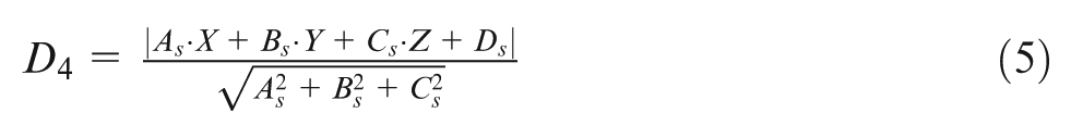
After obtaining the actual position of the hole at the top and bottom planes, the difference between the nominal and actual values (

Thus, the HPE could be calculated as follows
The above equations are very useful for studying the effect of locators’ position variation on HPE at the top and bottom surfaces. This study is conducted to optimize the layout of locators by using this mathematical model. Thus, the minimum value of the HPE has been used as the main function for optimization. The GA as an optimization tool is used in this article.
Optimization of fixture layout using GA
Because there is no certain relationship between the locators’ positions and workpiece error, the GA is used to determine the optimum locators’ positions in this article. GA is a computerized search and optimization algorithm based on the mechanism of natural genetics and selection. GA operates on a population of potential solutions applying the principles of “survival of the fittest” to produce better approximation solutions. At each generation, a new set of approximation is created by the process of selecting individuals according to their level of fitness in the problem domain and breeding them together using operators borrowed from the natural genetics. This process leads to the evaluation of population of individuals that they were created from just as in natural adaptation.22 The following assumptions are made in this work:
The workpiece and fixture elements are rigid; thus, deformations due to clamping or cutting forces are not considered.
The errors due to the machine tool and workpiece are not considered.
Each locator has a certain and fixed error.
The steps involved in this study are explained in detail as follows.
Initialization and representation
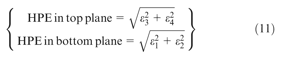
The first step of the solution phase is the initialization of candidate layouts. In this step, a particular coding method is used to change the layouts into numerical values. In the present problem, real variable coding is used. With respect to six locators and three vector coordinates for each one, a chromosome which represents a locator layout is made by 18 genes. After defining the chromosome, first population is produced randomly in the range which is specified by the user. A scheme of the chromosome is shown in Figure 7.
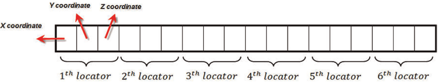
Chromosome representation in GA.
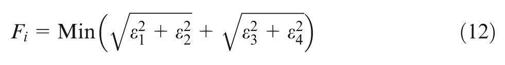
Evaluation of fitness
The HPE evaluated for each layout is used to calculate the fitness function of that particular layout. As shown in Figure 4, the hole position tolerance will be satisfied when the difference between the nominal and actual position at the top or bottom plane is in the tolerance range. The following fitness function is adopted in this work
Reproduction
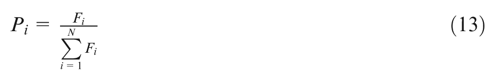
During reproduction, the layouts are selected from the population based on their fitness and a mating pool formed. There are many different types of reproduction operators which are roulettle_wheel selection, proportional selection, tournament selection, ranking selection, and so on.
2
Compared to other selection operators, the “roulettle_wheel selection” is the most common and a simple method for optimization. In roulettle_wheel, the probability of a layout being selected depends on its fitness
Crossover
Crossover is a genetic operator that combines two chromosomes to produce a new chromosome. The idea behind crossover is that the new chromosome may be better than both of the parents if it takes the best characteristics from each of the parents. There are some different crossover operators in GA. In this article, a modified uniform crossover operator is used. This crossover is useful for the search in the discrete space. A crossover mask, the same length as the chromosome structure, is created at random, and the parity of the bits in the mask indicates which parent will supply the offspring with which bits. Consider the following two chromosomes with 18 variables each


Offspring 1 is produced by taking the bit from parent 1 if the corresponding mask bit is 1 or the bit from parent 2 if the corresponding mask bit is 0. Offspring 2 is created using the inverse of the mask. Suppose the crossover mask is


Mutation
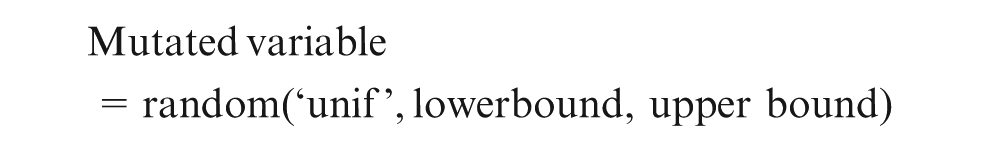
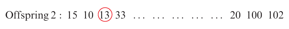
Mutation is a genetic operator that changes one or more gene values in a chromosome from its initial state. With these new gene values, the GA may be able to arrive at better solutions than was previously possible. Mutation prevents falling the population into a local optimum. Mutation probability is used to identify the number of chromosomes that must be mutated. The mutation probability should usually be set low. Otherwise, the search will turn into a random walk. In a uniform mutation operator which is used in this article, the value of the chosen gene is replaced with a uniform random value selected between the user-specified upper and lower bounds for that gene. The mutation of a chromosome is obtained by the following rule
For example, if the third variable of offspring 2 above is chosen for the mutation, the mutated offspring may look like this
Elitist strategy
The elitist strategy ensures that the best individual will not be lost in future generations. In this step, the best solutions from the population are maintained in the next generation so that the convergence is faster. In this article, the elitist strategy is implemented in several parts as follows:
In initial population. The first population is selected among the 10 times of population size that was generated randomly.
In reproduction Half of the population is selected randomly and entered in the mating pool without changing and the other half will be selected according roulettle_wheel selection.
In crossover. Two better chromosomes from previous generation enter into the next generation without changing.
In mutation. One of the best chromosome from previous generation enters into the next generation without changing.
Testing for termination criteria
The algorithm can be terminated by specifying different conditions like the number of generations, specific objective value, and improvement of the objective function in successive generations. In this work, the algorithm will be terminated if the iteration number increases to the maximum number of generations specified in the GA routine.
GA validation
In this study, fixture layout optimization is implemented using the developed software written in MATLAB language. The flow chart shown in Figure 8 explains the procedure adopted. Two test cases are used to validate the written GA program. Both test cases have several local minimum points and only one global minimum point.
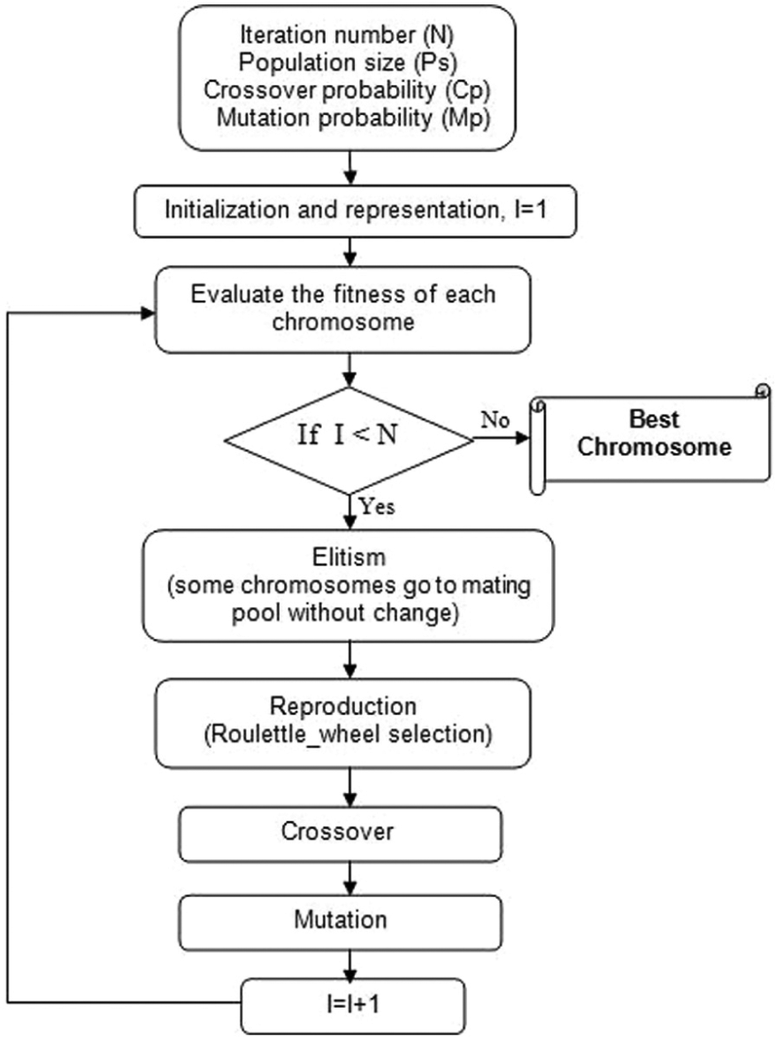
The flow chart of analysis.
Test case 1
The first test case function as given in equation (14) has two variables, and their upper and lower bands are
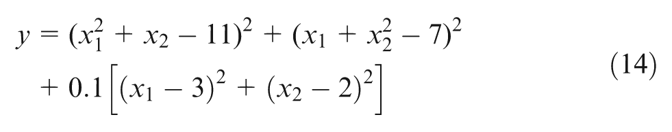
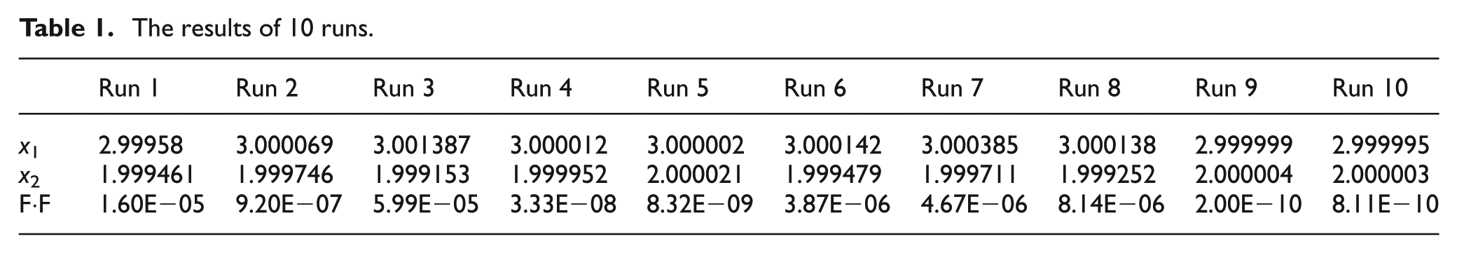
With the same parameters used by Kaya, 6 the results of 10 runs are given in Table 1. The results show that the GA successfully converges to the global minimum.
The results of 10 runs.
Test case 2
The function of the second test case has been shown in Figure 9. According to the figure, the value of the global minimum point is −22.6743.
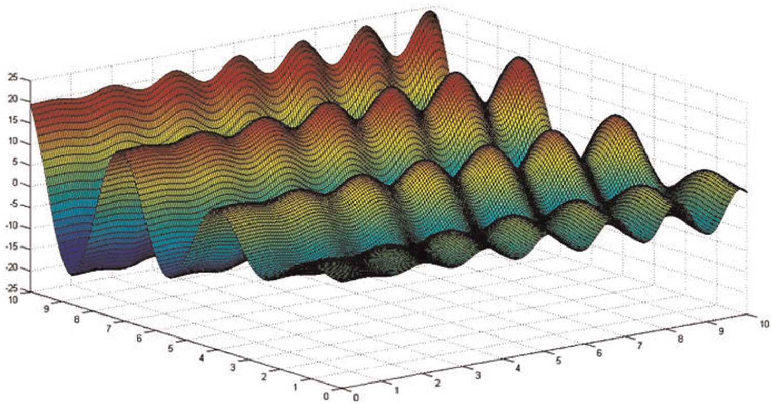
The function of test case 2.
This function is as follows

Using the above conditions, the best result occurs at (9.0390, 8.6682) with a function value of −22.6908.
Case study
The workpiece studied by Rong 10 is taken for analysis. The part is simplified from a real part and shown in Figure 10.
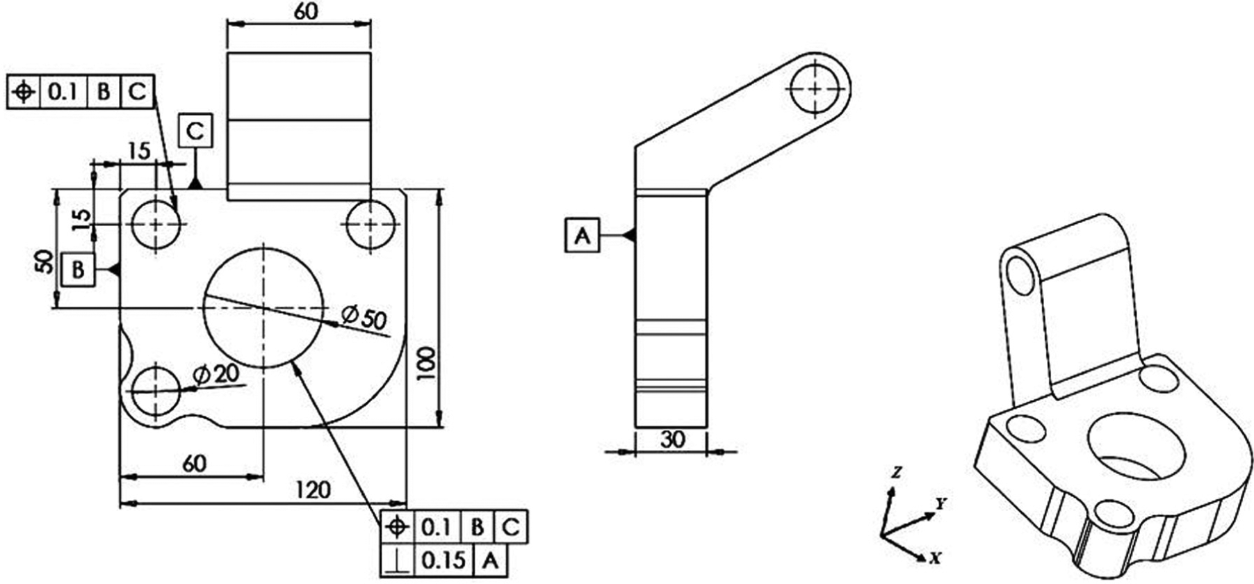
Example of part model.
In this part, two holes have position tolerance. So, a comparison of the tolerances is necessary to determine the critical tolerance. A tolerance factor is applied to identify which tolerance is tighter. Tolerance factor is defined as follows 21
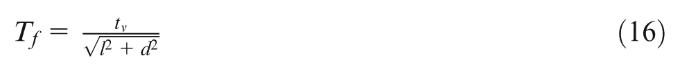
where
The tolerance factor values for two position tolerances have been calculated in equations (17) and (18), respectively
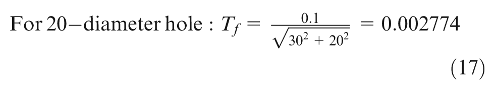
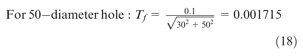
It is clear that the 50-diameter hole has tighter tolerance, and this hole should be considered as the main candidate for optimization.
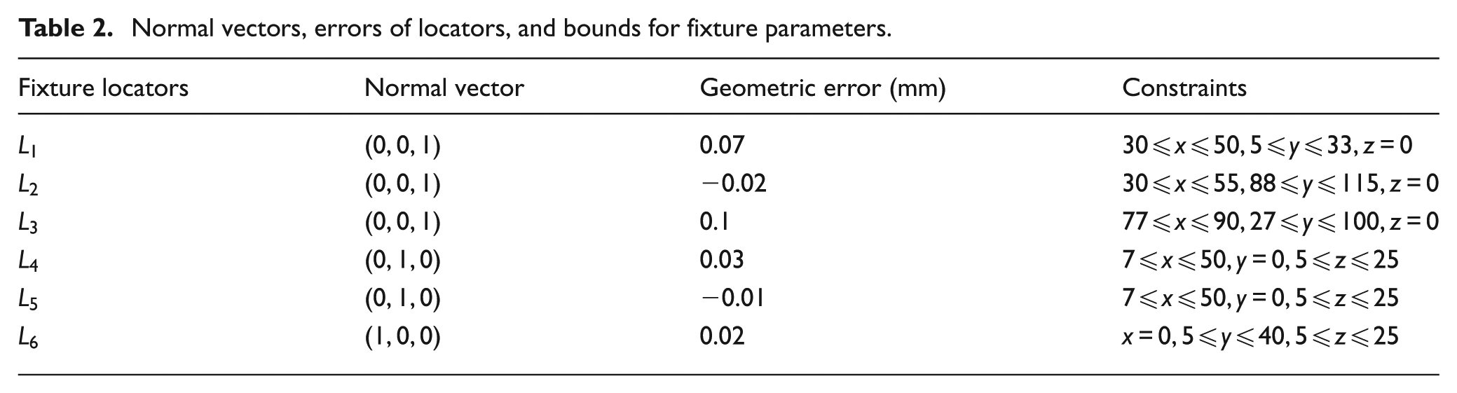
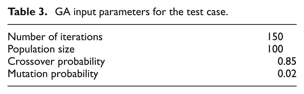
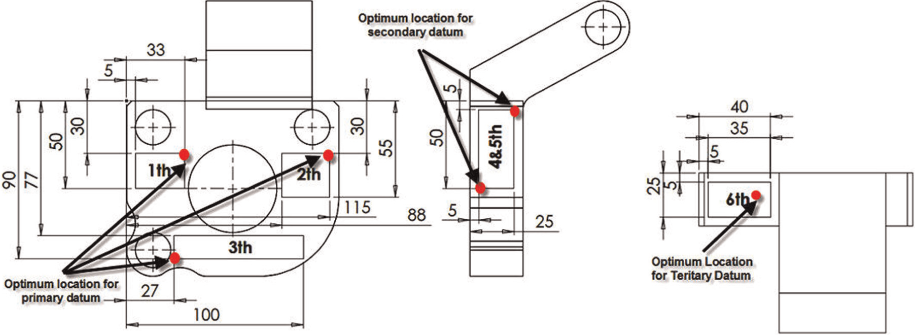
The critical dimension is the distance of the center of the hole from the lateral edges of the workpiece. Hence, the aim is to achieve the minimum possible machining error in this feature and to determine the corresponding fixture parameters. Rong has investigated the impacts of locator distribution on position, profile, and parallelism tolerances using two locating layouts. However, the optimal layout was not determined in his research. In this article, an optimal layout is obtained by using GA. Table 2 shows the normal vectors, geometric error of the locators, and the possible locating bounds used for each locator in the optimization process as shown in Figure 11. The GA parameters used in this work are shown in Table 3:
Normal vectors, errors of locators, and bounds for fixture parameters.
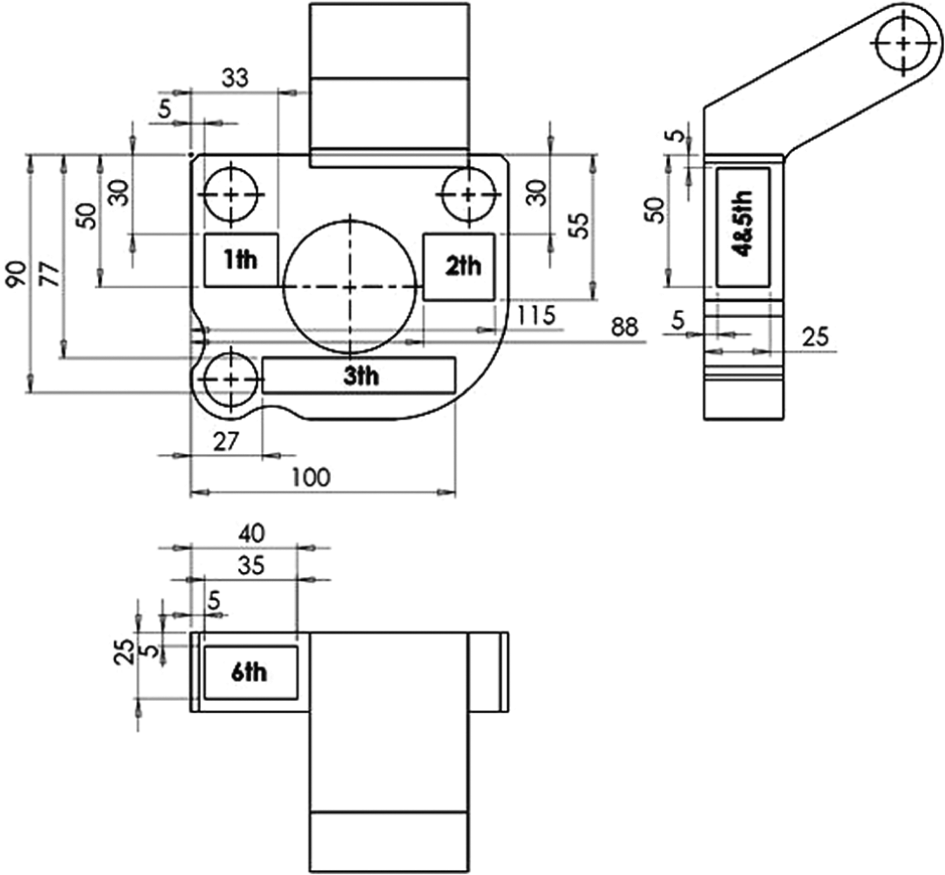
Six regions for locators.
GA input parameters for the test case.
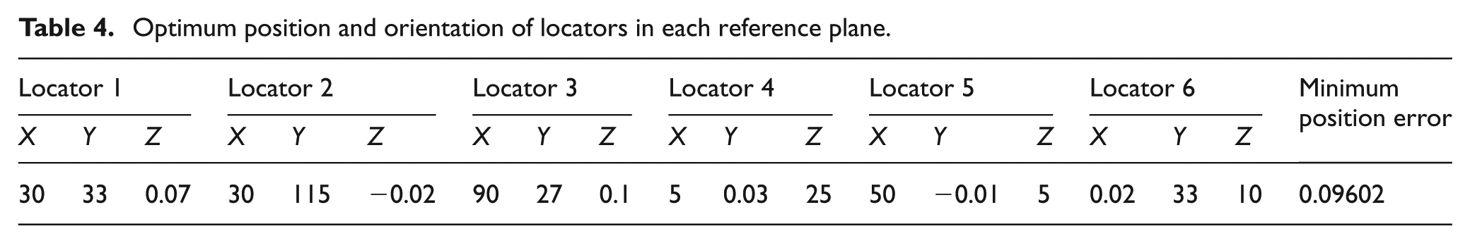
The objective of the optimization run is to achieve the minimum possible HPE as discussed earlier. The optimal layout and the corresponding optimal HPE after 50 GA run are shown in Table 4. The minimum positional error achieved is 0.09602 mm. Also, the schematic of the locators’ position is shown in Figure 12.
Optimum position and orientation of locators in each reference plane.
Locators’ layout after optimization.
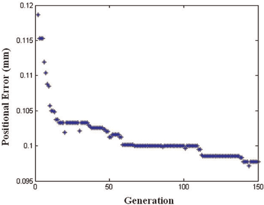
As discussed earlier, the optimization process is terminated if the iteration number increases to the maximum number of generations. Figure 13 shows the convergence of the GA. A good improvement in the objective function values can be seen in the figure. The error was as high as 0.19 mm in generation 1, and it gradually decreases to the final value of 0.09602 mm (an improvement of 49.47%). Also, the final value (0.09602 mm) is within the specified position tolerance (0.1). As a result, the current layout is acceptable for machining.
The convergence of GA for case study.
In comparison with the result obtained in the study 10 by Rong, the GA approach proposed by this study has several advantages. Rong studied only the effect of two locators’ layout on the workpiece error and proposed a method for comparing the different locating approaches without any offer for optimal locating layout. However, in the GA approach, an optimal layout is finally determined. Furthermore, a mathematical model has been developed and used in the optimization problem. The case study shows that the GA method based on the mathematical model can be used to calculate locating errors and find the optimal locating layout within the specified tolerance range. It is critical for fixture design in hole-making process.
Conclusion
This article presents a GA optimization method for the determination of fixture parameters. The optimization procedure is to minimize the HPE in the hole-making process. For calculating hole positional error, a mathematical model has been developed by mapping the planes of the workpiece actual coordinate system in the workpiece theoretical coordinate system. The developed GA uses some elitism strategy that leads to faster convergence. Two test cases verify the developed GA optimization model. A case study is used to show the application of the GA model. The result proposes a fixture locator layout so that the position tolerance is within the tolerance range. The output of this module is as an input for ongoing research on workpiece stability in automatic fixture.
Footnotes
Declaration of conflicting interests
The authors declare that there is no conflict of interest.
Funding
This research received no specific grant from any funding agency in the public, commercial, or not-for-profit sectors.