
Abstract
Five-axis frontal grinding has an advantage in finish machining of freeform surface due to high surface accuracy and material removal rate. This article focuses on achieving nearly constant machining strip width with toroidal cutter. To begin with, the initial tool path is generated to realize the maximum machining strip width with fixed yaw angle at each cut contact point and then the verges of machined area convergent to the effective machined area after modifying tool posture. The experimental test shows that the proposed method can obtain quasi constant machining strip width.
Introduction
Five-axis grinding technology meets the high requirements concerning the contour and surface accuracy of free formed components, such as turbine blades, consumer products and dies. In the past, five-axis belt grinding was widely used in mold and turbine blades’ manufacturing, but the grinding belt cannot be dressed and has low material removal rate. Toroidal grinding tools can reach higher material removal rate and shape accuracy than grinding belt.
Due to high material removal rate, 1 the frontal grinding strategy is advantageous for grinding of less curved surfaces. However, if the contact length between grinding wheel and workpiece varies greatly, the variation in thermal and mechanical loads would influence the surface quality, and grinding burn may occur when the contact length is too long. High-speed grinding is possible to reduce the amount of heat in the grinding process, but not all workpiece materials permit high-speed grinding. 2 Besides, many researchers focus on estimating the maximum grinding temperature,3,4 which can effectively prevent thermal damage. In addition, a higher specific removal rate corresponds to a higher burn threshold level. Therefore, it is actually meaningful but a great challenge for achieving constant material rate in five-axis grinding. Complex contours like that of the knee joint can be produced with high contouring accuracy and constant material removal by varying the angle and the feed speed according to the changing surface. 5 Some approaches for achieving constant material removal rate are conducted by breaking up the tool path and adjusting feed rate frequently, 6 but adjusting feed rate at a small length interval may cause jerky machine movement that would compromise surface finish.
A method proposed to achieve quasi constant machining strip width within each tool path and the constant material removal rate can be obtained approximately. Furthermore, the tool path smoothness is also taken into account.
Tool positioning strategy
In advanced multi-axis tool positioning methods, some good results were achieved with the methods of Strutz 7 and Principal axis method (PAM), 8 which are popular and easy to conduct. A better conjugate matching between the cutter and surface could be obtained with the multi-point machining (MPM) 9 method for searching two cut contact (CC) points, but this method is too complicated to be implemented in practice.
In this article, the cutter is positioned at the CC point with two rotation angles to achieve the maximum machining strip width. Specifically, the toroidal cutter contacts the workpiece surface at point
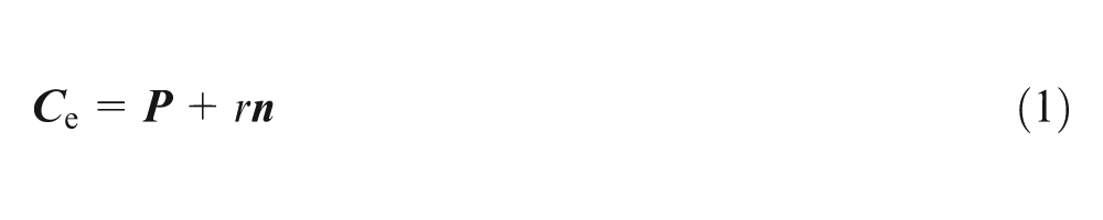
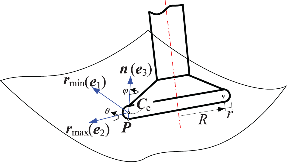
Tool position determination.
where
Initial tool path generation
Iso-parametric method is used for tool path generation. By keeping one of the two parameters constant, CC points are generated along the other parameter of a parametric surface. Although the minimum curvature direction is not always the optimal feed direction, it can still be considered as an applicable feed direction since it would result in a wide machining strip width. Thus, the iso-parameter curve that is closer to the minimum curvature direction should be chosen for tool path generation.
For instance, a tool path is generated along the iso-parameter curve v = v
0 and the CC points are (u
1, v
0), (u
2, v
0),…, (un
, v
0) successively, where n is the number of CC points. Xu et al.
10
pointed out that the machining strip width was more sensitive to the tilt angle than the yaw angle. Fard and Feng
11
researched the machining strip width variation in cylindrical surface machining and found that the machining strip width sharply reduced in a small tilt angle interval. Therefore, in order to smooth tool axis variation, the yaw angle can be fixed in some way. For less curved surface, the tool axis can be fixed in the normal plane that passes through the minimum curvature direction by setting the yaw angle as 0. Generally, smaller tilt angle reaches larger machining strip width for the given yaw angle, but gouge may occur when the tilt angle becomes too small. Hence, the critical tilt angle can be determined by bisection method. Finally, the yaw angle
Quasi constant machining strip width calculation
Effective machined area
According to section “Initial tool path generation,” iso-parametric tool paths can be calculated one by one to cover the entire workpiece surface S(u, v). The parametric representation of machining strip width at CC point (ui , v 0) (i = 1, 2,…, n) can be defined by
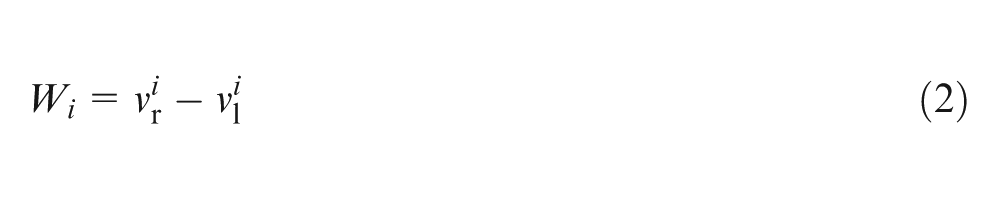
where
As discussed above, the fluctuation of machining strip width within a tool path can be reduced when the machined area converges to the effective machined area, as shown in Figure 2. Furthermore, it is helpful to make the material removal rate more stable and avoid unnecessary repeat cutting.
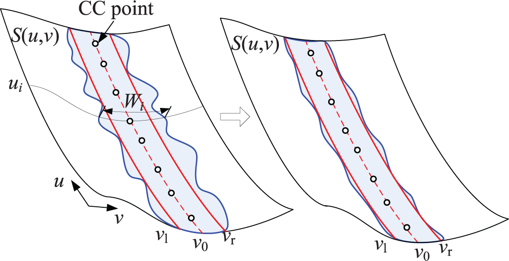
Machined area of a tool path.
Tool posture modification
In order to achieve quasi constant machining strip width, tool posture should be modified at each CC point. The cutter can be lifted up along the normal vector at CC point with a distance δ, which is called lift value and satisfies 0 ≤ δ ≤ Δ, where Δ is the given tolerance. Obviously, δ equals to 0 at each CC point.
Tool posture modification is conducted by adjusting the tilt angle and lift value without changing the yaw angle. It is well-known that the machining strip width decreases as the tilt angle increases or the lift value increases, as shown in Figure 3. The surface ABCD reflects this trend clearly, and the four points are A(θ A, 0, W A), B(θ B, 0, W B), C(θ B, Δ, 0) and D(θ A, Δ, 0). The point A has the smallest feasible tilt angle and the maximum machining strip width. For instance, θ A = θi and W A = Wi at the CC point (ui , v 0) according to section “Initial tool path generation.”θ B corresponds to the biggest feasible tilt angle (always equals to 90°) and W B is very small. The machining strip width reduces to 0 when the lift value equals to the tolerance, which means the cutter is lifted up outside the tolerance zone.
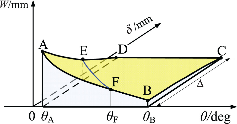
Variation in machining strip width with different tilt angles and lift values.
The purpose of tool posture modification is to make the machined area [
Tilt angle smoothing
The left convergence point E at CC point (ui
, v
0) satisfies θ
Ei
= θi
, and the right convergence point F can be found to increase the tilt angle till one of the machined area verges
It is better to increase tilt angle rather than the lift value to reduce the machining strip width, because lift value almost has no effect on the material removal when the grinding depth is much bigger than the tolerance. Therefore, the right convergence point F(θ Fi , 0, W Fi ) can be found at each CC point (ui , v 0), and the original tilt angle θi = θ Ei can be replaced by θ Fi . However, sometimes the tilt angle sequence θ F1, θ F2,…, θ Fn−1, θ Fn causes fluctuation of tilt angle; thus, a smoothing method is proposed to improve it.
A slope function zi is defined at point (ui , θ Fi ) (2 < i < n − 1) to evaluate the tilt angle smoothness. That is
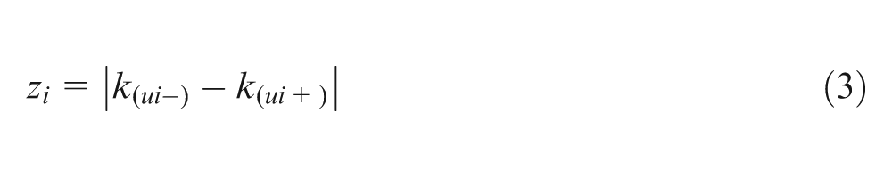
where k (ui−) = (θ Fi − θ Fi−1)/(ui − ui −1) and k (ui+) = (θ Fi+1 − θ Fi )/(ui +1 − ui ).
An accuracy ε z (ε z > 0) can be given according to requirement and experience, and the points that satisfy zi > ε z are chosen as bad points. Then, at each bad point, a cubic Hermit curve is built with neighboring points to smooth the tilt angle transition. In detail, if point (ui , θ Fi ) is a bad point, the cubic Hermite curve H 3(u) can be defined as
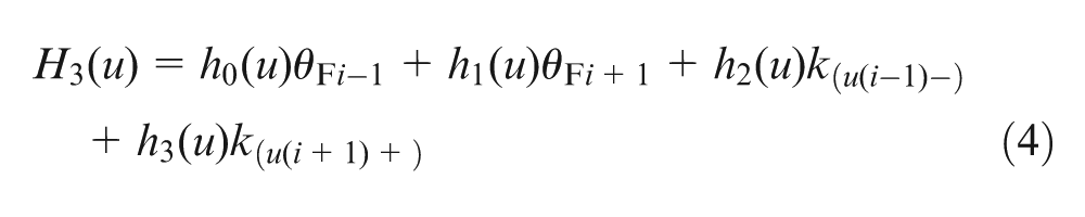
where
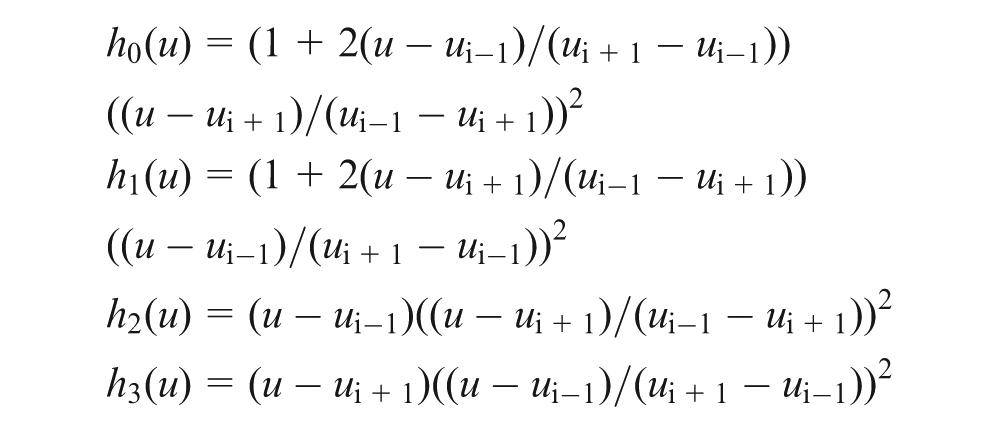
The interpolation result of the cubic Hermite curve can be obtained by taking u = ui into equation (4) and represented as H 3(ui ). As discussed in section “Tool posture modification,” the tilt angle at CC point (ui , v 0) should be controlled in the interval [θ Ei , θ Fi ] to achieve a convergence point. θ Ei is the critical tilt angle and smaller tilt angle will cause gouging. θ Fi corresponds to the right convergence point, and more bigger tilt angle may cause undercut between neighboring tool paths. Therefore, there are three cases: (1) if H 3(ui ) > θ Fi , then the optimal tilt angle θ opti = θ Fi ; (2) if H 3(ui ) < θ Ei , then θ opti = θ Ei and (3) if θ Ei ≤H 3(u i) ≤ θ Fi , then the optimal tilt angle θ opti is H 3(ui ). In case 1, although (ui , θ Fi ) is a bad point according to the given accuracy ε z, θ Fi is already the optimal tilt angle. The above smoothing process is shown in Figure 4.
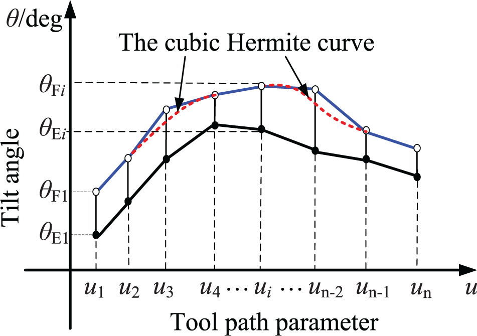
Tilt angle smoothing process.
After obtaining the optimal tilt angle θ
opti
, the optimal convergence point is the intersection point of the curve EF and the section curve with equal tilt angle θ
opti
. There are three cases: (1) if θ
opti
= θ
Fi
, then the optimal convergence point is F and the lift value δ
opti
= 0; (2) if θ
opti
= θ
Ei
, then the optimal convergence point is E and δ
opti
= δ
Ei
and (3) if θ
opti
= H
3(ui
), then the optimal convergence point is in the middle of the curve EF. In cases 2 and 3, the lift value can be found with bisection method, as shown in Figure 5. The optimal lift value can be found when the machined area contains the effective machined area of the tool path, and one of their verges is close to each other in the given convergence accuracy e, which can be represented as
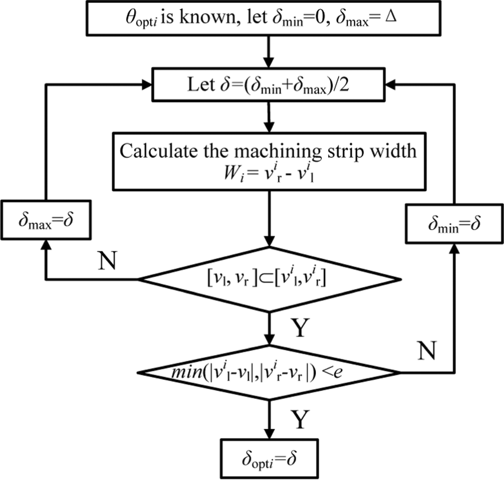
Calculation of the optimal lift value.
Calculation and verification
A toroidal cutter with a torus radius R = 6.5 mm and an insert radius r = 1.5 mm was used to calculate tool path on a turbine blade, as shown in Figure 6.
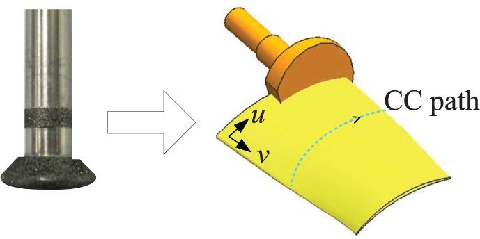
Toroidal cutter and turbine blade.
A tool path along the iso-parameter curve v = 0.5 was calculated with fixed yaw angle
After adjusting the tool posture at each CC point with the proposed method in section “Quasi constant machining strip width calculation,” quasi constant machining strip width is obtained as the path verges are convergent to the effective machined area, as shown in Figure 7. The left and right convergence tilt angles are shown in Figure 8, and the right ones, few of which are smoothed with cubic Hermite curve, are chosen as the optimal tilt angles.
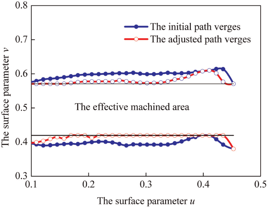
Tool path verges before and after adjustment.
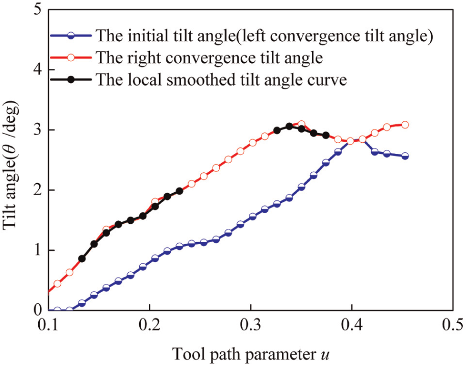
Convergence tilt angle and smoothed ones.
Conclusion
An algorithm is introduced to achieve quasi constant machining strip width in five-axis frontal grinding of free surfaces with toroidal cutter, and the optimal tilt angle curve is smoothed to some extent. The proposed method can be applied in the finishing grinding process, which is found useful to control the contact length and avoid grinding burn.
Footnotes
Appendix 1
Declaration of Conflicting Interests
The author(s) declared no potential conflicts of interest with respect to the research, authorship, and/or publication of this article.
Funding
The author(s) disclosed receipt of the following financial support for the research, authorship, and/or publication of this article: The authors would like to gratefully acknowledge the financial support from the National Science and Technology Major Project of China (No. 2013ZX0401 1031).