
Abstract
Fast tool servo–assisted ultra-precision diamond turning has been extensively regarded to be a very promising technology for the fabrication of optical freeform surfaces, and micro- and nano-structured surfaces with high efficiency and high surface quality. This article describes a changing feed-rate tool path which can adjust the tool position arbitrarily both in the x-direction and z-direction to obtain homogenous surfaces. Meanwhile, it can improve machining efficiency, save cutting parameters calculation time, and avoid over-cutting at workpiece center. Cutting experiment is carried out to implement the new tool path.
Introduction
Single-point diamond turning technology is widely used in the fabrication of optical lenses which enables the fabrication of optical-quality surfaces with accurate geometries and fine surface finish. With the rapid development of optics, the geometry of optical elements has become more and more complex, such as optical freeform surfaces,1,2 and micro-and nano-structured surfaces.3–9 With the advent of improved machines and processes, interest has been growing for a fast tool servo (FTS) mechanism to increase the capability and capacity of existing machines. The purpose of the FTS is to move the tool small distance in and out of the workpiece several times per revolution of the part, thus generating non-rotational symmetric surfaces or motion error compensation.
In recent years, FTS technology has been well developed in FTS device design,10–13 optimization of machining parameters,14,15 trajectory tracking control algorithm,16,17 and tool path generation method.18–20 In order to obtain high-profile precision and surface roughness, except high-precision FTS system, the cutting parameters must be calculated carefully, including tool geometry and feed rate. Then, the tool path is generated with tool radius compensation. However, since an FTS has but one degree of freedom (DOF) of motion, the workpiece is machined with constant feeding rate. The surface roughness will be different if the surface curvature changes. The machining efficiency will be reduced to ensure that the maximum surface roughness meet the requirement. Else, over-cutting happens at the workpiece center if the center slope is not zero, such as the inclined surface. 21
In this article, a changing feed-rate tool path generation method for FTS diamond turning is described. The purpose of the new tool path is to change the feed rate in realtime according to the surface curvature to generate a homogenous freeform surface. Meanwhile, it can save machining time, avoid over-cutting, and save calculation time by which the feed rate can be calculated during the tool path generation.
The relationship of the surface scallop height and the curvature radius
In diamond turning, the contact point of the turning tool nose circular arc and the surface is defined as the cutter-contact point (CCP), and the cutter-location point (CLP) is the point which determines the location of the tool. The surface scallop height is decided by the distance of the adjacent CCPs. Usually, the side step distance is constant over the whole surface because of the x-slide moving at a constant speed. Figure 1 shows the relationship between the surface scallop height H and the curvature of the freeform surface R′; the distance of the two adjacent CCPs is L and r is the tool nose radius.
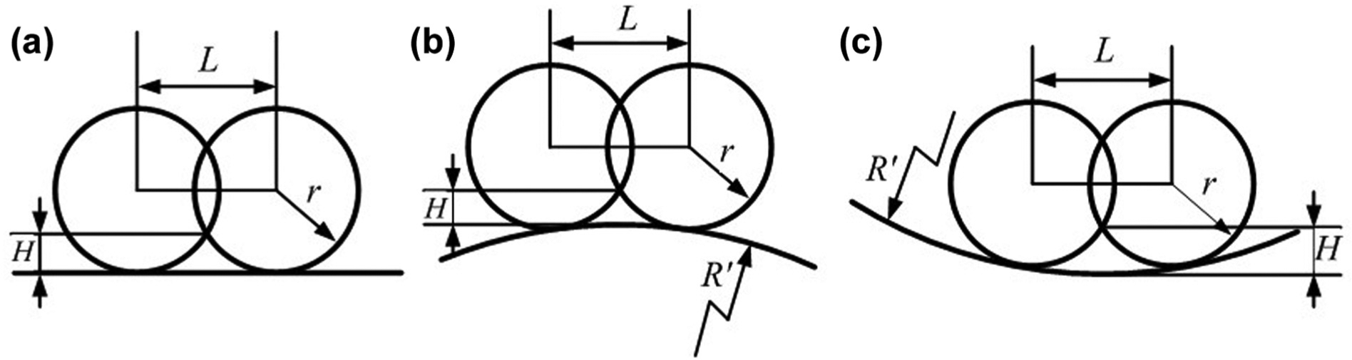
The sketch map of the surface scallop height: (a) flat surface, (b) convex curvature surface, and (c) concave curvature surface.
According to the geometrical relationship shown in Figure 1, the theoretical formula of the surface scallop height can be obtained. 22 The surface scallop height of the flat surface can be expressed as
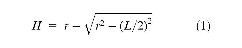
and of the convex curvature surface as
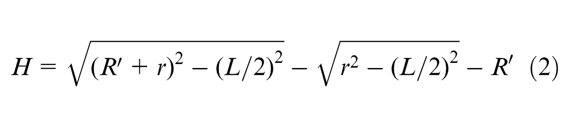
The surface scallop height of the concave curvature surface is
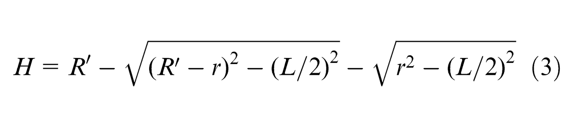
Evidently, the smaller the curvature radius, the greater the impact on the surface scallop height, and the concave surface is much smoother than the convex surface. A freeform surface usually contains different types of surfaces; the normal turning process makes the machined surface non-homogenous which may degrade the optical performance. This problem can be resolved by reducing the feed rate to obtain an approximately homogenous surface. 23 However, the processing cycle will be extended. In the next section, the new tool path to obtain constant scallop height is described.
Changing feed-rate tool path generation
The constant-angle method 23 and sectional curve method 18 are used in this article. The constant-angle method divides the surface into a certain number of sectional curves. The surface scallop height is decided by the distance of the two adjacent CCPs on the same sectional curve. The CCPs’ positions of every sectional curve are calculated first according to the initial cutting points and the scallop height. Next, the corresponding CLPs are obtained. Then, the tool path is generated by seriating these CLPs along the circumferential direction. The details are described as follows.
Basic information
The cutting point schematic drawing is shown in Figure 2. P
i
and Pi+1 are the CCPs, and
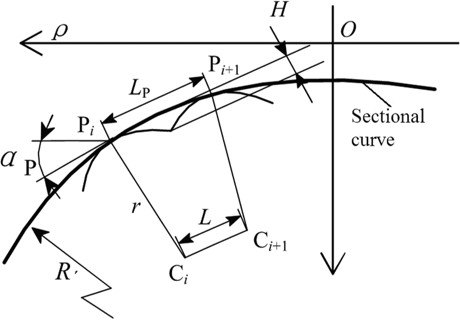
Schematic drawing of cutting points.
In the workpiece coordinate system, the freeform surface can be expressed by

According to Lin and Koren, 24 the distance LP of different surfaces can be obtained as
(a) the flat surface:

(b) the convex surface:

(c) the concave surface:

where H is the surface scallop height and the curvature radius
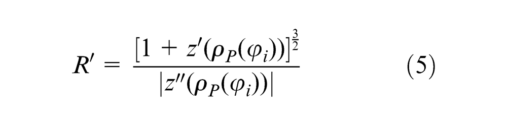
Before every calculation, the convex–concave property of the surface must be judged to choose the corresponding LP for further calculation. For a given surface, the second derivative of arbitrary points can be obtained. The convex–concave property of the calculating point can be judged by testing the positive or negative of the second derivative. If the second derivation of the point is equal to zero,
Tool path calculation of the initial CCPs
In this method, only the scallop height is the known quantity. In order to calculate all of the cutting points, the first turn cutting points position must be calculated first, including the CCPs’ position and CLPs’ position.
First turn cutting points’ position calculation
The workpiece is machined from outer circle to the center so that the initial CCPs are the outmost circle CCPs, which are calculated by the single-axis linear FTS tool path generation method. 25 The feed rate of the first turn is a key factor which will affect the continuity of the latter cutting points. The surface scallop is first formed by the first cutting point and the adjacent point on the same sectional curve. Therefore, the distance between these two points is the feed rate of the first circle.
For the first cutting point P1,
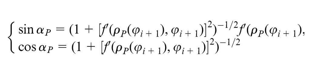
The polar coordinates of the CLP
where
The feed rate of the first turn is
Remainder cutting points’ position calculation
The other cutting points are calculated by first turn cutting points and the scallop height H as follows.
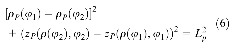
(1) CCPs calculation. According to the geometrical relationship shown in Figure 2, for two arbitrary adjacent CCPs of the same sectional curve, the following formula can be obtained
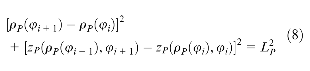
The radial coordinate
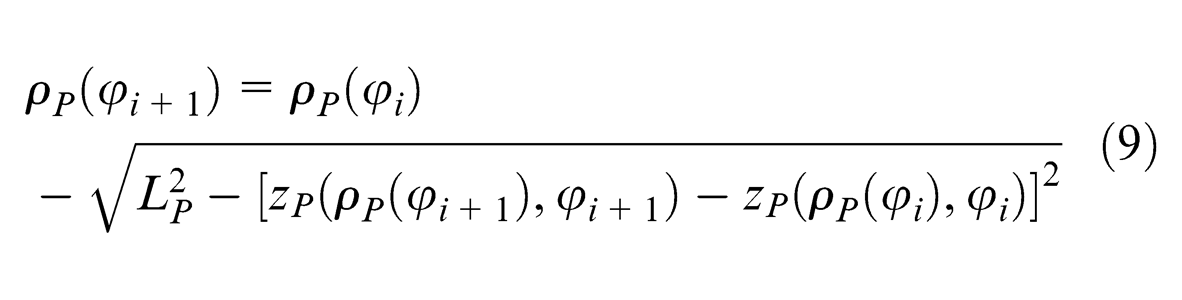
where
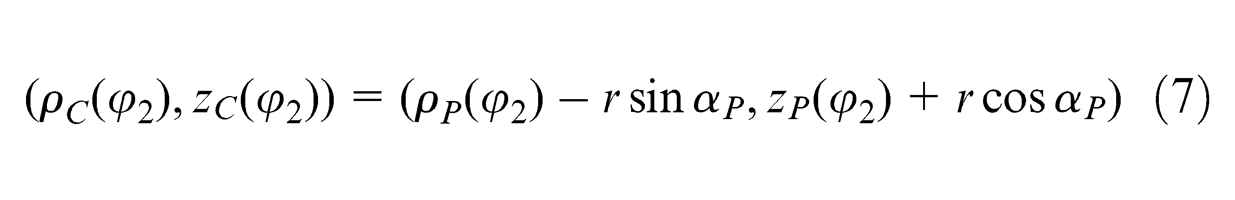
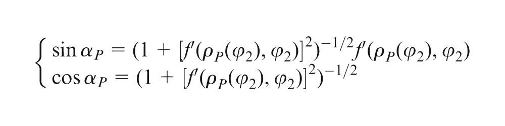
(2) CLPs calculation. The polar coordinates of the CLP
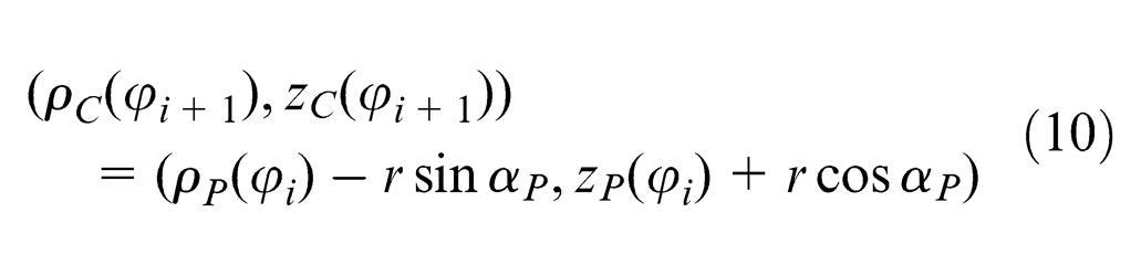
where
Feed-rate calculation and tool path generation
x-slide feed-rate calculation. Loop calculating step (1) and step (2) can obtain all the CLPs of one sectional curve, and then every sectional curve of the freeform surface. The value
Tool path generation. For the FTS machine technology, in which the spindle rotates and the x-slide moves at a constant speed,
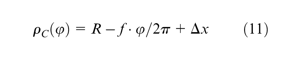
where
Then, the tool path is obtained:
An example of a new tool path
A sinusoidal surface is used to explain the new tool path, as shown in Figure 3. It can be seen that the cutting points are sparse at the concave surface region and dense at the convex surface region. The tool path contains two parts: the z-direction displacement and the x-direction displacement. The x-direction displacement can be decomposed into the trend component and the fluctuation, as shown in Figure 3(b) and (c). Therefore, except the constant-speed working spindle and the x-slide, the diamond tool must be able to move rapidly forth and back in both the x-direction and z-direction.
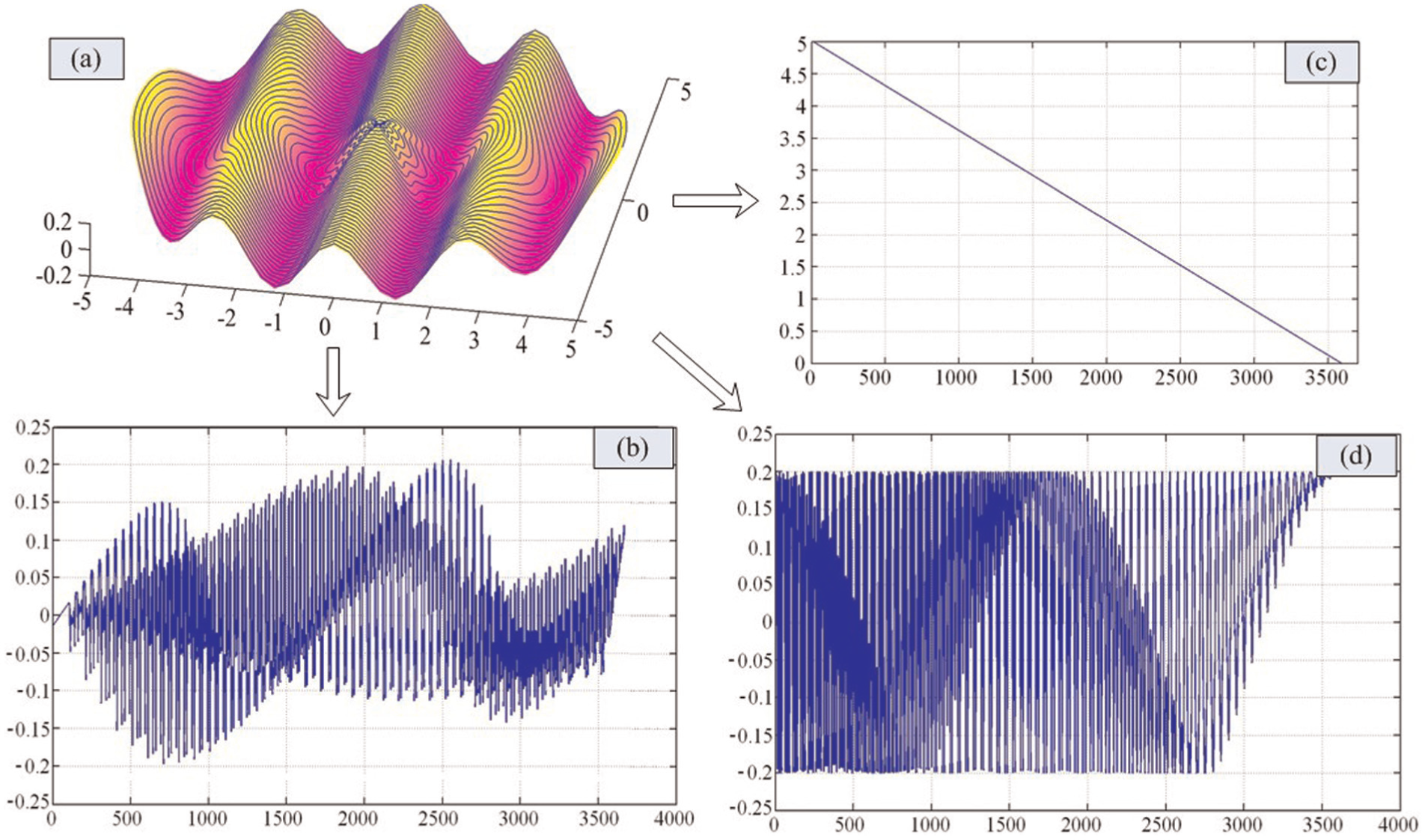
Schematic drawing of the tool path: (a) the approximate spiral tool path, (b) the x-direction short stroke jump, (c) machine tool x-slide feed rate, and (d) the z-direction tool trajectory for FTS.
For a sinusoidal surface with a radius of 5 mm, amplitude of 50 µm, and wave length of 2.5 mm while the scallop height H of 30 nm, the feed rate calculated by the new tool path is 10.8 µm. The feed rate used in the constant rate feed cutting process to obtain a surface with a scallop height H less than 30 nm is 9.7 µm. The machining efficiency is improved by 11.3%, which is affected by surface geometry and scallop height. While the new tool path can adjust tool position arbitrarily both in the x-direction and z-direction, over-cutting at the center of workpiece can be avoided.
Freeform surface cutting experiments
The cutting experiments were carried out on a diamond turning machine to implement the new tool path. The spindle is fixed on the base, and a 2-DOF FTS is fixed on the slide, which can move along the x-axis and z-axis directions. The tool nose radius is about 0.5 mm. A 6061 aluminum part with a diameter of 10 mm was used for the cutting experiments. A sinusoidal surface with an amplitude of 30 µm is machined on the flat face. The scallop height H is 0.1 µm, while the theoretical surface roughness is Ra 12 nm.
The part is machined at 90 r/min. The maximum tool cutting depth is 40 µm, and the minimum tool cutting depth is about 10 µm. The final cutting result is shown in Figure 4. The surface roughness is measured by an OLS3000 Laser Scanning Confocal Microscope. Generally, except tool nose radius and feed rate, surface roughness is affected by tool vibration, tool wear condition, and material characteristic or other reasons in the actual cutting process. It means that the actual obtained surface roughness value is usually larger than the theoretical value, and absolutely homogenous surface cannot be obtained. Therefore, the measured value is about Ra 20 nm larger than the theoretical value 12 nm.
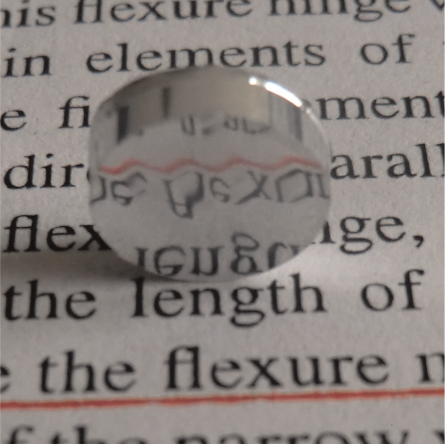
Sinusoidal surface workpiece photo.
Conclusion
This article presents a new tool path for optical freeform surfaces FTS diamond turning, which can adjust tool position arbitrarily both in the x-direction and z-direction. The new tool path can improve the optical freeform surface machining frequency and avoid over-cutting at the workpiece center, while the slope of the workpiece center is not zero. Besides, it can save cutting parameter calculation time by obtaining the feed rate during tool path generation, which is a most important parameter for surface roughness. The machining result shows that this new tool path can be used to fabricate optical freeform surfaces.
Footnotes
Declaration of conflicting interests
The authors declare that there is no conflict of interest.
Funding
This work was jointly supported the National Science Foundation of China (51175221), and the Department of Science and Technology of Jilin Province (20130522155JH).