
Abstract
Ultrasonic-assisted machining is a method used to improve the machining technologies and overcome some problems in recent decades. To achieve optimal machining performance during hard turning, proper selection of turning parameters is considered as an important issue. The process becomes more complicated when methods such as ultrasonic-assisted machining are applied and ultrasonic vibration variables are also extracted. In this research work, a methodology is proposed to optimize ultrasonic-assisted turning process during machining of hardened steel AISI 4140. Neural network was employed to model process outputs (surface roughness and cutting force). Then electromagnetism-like algorithm was coupled to neural network to maximize the material removal rate with regard to outputs of process as constraints to achieve the machined part requirements. Experimental design technique was also used to obtain the needed experimental data for training neural network to predict process outputs. Material removal rate constitutes the main function of the electromagnetism algorithm; cutting force and surface roughness were applied as the constraints of the electromagnetism-like algorithm function. The unconstrained objective function that was created using penalty method was then optimized by the electromagnetism-like algorithm and genetic algorithm codes. It was observed that electromagnetism-like algorithm has more accurate results in comparison to genetic algorithm. Finally, the obtained optimum variables were experimentally tested in order to examine the mentioned method. Good compatibilities are observed between the values of optimization method and the experimental measurements.
Keywords
Introduction
Along with the competitive environment of manufacturing, development of novel machining techniques and their optimization are essential to satisfy the market demands in a short and efficient manner. 1 The machining technologies have always encountered different challenges such as machining hard and brittle materials, achieving better surface quality, required dimensional and geometrical tolerances, reducing machining forces, increasing the durability of the tools and reducing the burr size. Studies in different fields are done to fulfill the industrial needs, improving the cutting tools, machineries and chip removal methods.2,3 Using ultrasonic vibrations has been considered as one of the solutions to improve the machining technologies and overcome some problems in recent decades. In this method, in order to improve efficiency of the process, low-amplitude vibrations with the frequency of 20–30 kHz are exerted to conventional machining. The vibrations prevent the tool to be in continuous contact with the workpiece, transforming the cutting mechanism to vibro-impact cutting conditions. The vibro-impact cutting condition can reduce friction interaction in the cutting area and improve the cutting condition in many fields.4–6 To have intermittent contact between the tool and the chip, the cutting speed in ultrasonic-assisted turning (UAT) should be smaller than a certain limit that is called critical speed, which is shown in equation (1)

where Vcrit is the critical speed, fr is the vibration frequency and a is the vibration amplitude.
If Vc < Vcrit, cutter releases from chip contact during each cycle of oscillation with frequency of fr. Reduction in cutting force and tool wear in the UAT can be the result of the intermittent engagement between tool and chip. 7
Ultrasonic vibration has been extensively adopted in manufacturing processes. Ultrasonic-assisted cutting method can solve the chatter vibration even using a large nose radius that leads to a stable cutting and a precise surface finish. 8 Suzuki et al. 9 showed that ductile cutting can be achieved in ultrasonic-assisted machining of tungsten alloy that can produce an optical quality surface finish. The analytical results presented by Babitsky et al. 10 demonstrated that UAT can improve the surface roughness and roundness. By increasing the tool vibration parameters (frequency and amplitude), and decreasing the cutting speed, the tool–workpiece contact ratio (TWCR) reduces. As a result, any reduction in TWCR reduces cutting force, surface roughness and tool wear.11,12 Suzuki et al. 13 applied elliptical vibration cutting technology successfully to form nano-scale sculptures on the hardened steel.
Surface roughness and dimensional accuracy of produced parts are considered as crucial issues in machining process. The shape accuracy of a produced part is a function of machining accuracy. There are numerous factors that can lead to machining inaccuracy in metal cutting. The deflection of tooling system under cutting forces is a major cause of inaccuracy. All engineering drawings contain surface roughness and required tolerances that should be fulfilled during machining. As a result, it is essential to choose cutting conditions in an optimum manner. The optimization should minimize the attributed costs, meanwhile satisfying the customer requirements in surface roughness and tolerances.14,15
In order to achieve optimal machining performance, parameters of turning process should be properly selected. This fact becomes more complicated when methods such as ultrasonic-assisted machining are applied. In addition, ultrasonic vibration variables should be adjusted and also optimally extracted. So the application of optimization methods in turning processes is considered as crucial issue in the presence of enhancement of product quality and processes.
In the recent years, many neural network (NN) models have been developed to evaluate the surface roughness and cutting forces in several materials.16–18 Additionally, researchers combined NNs with genetic algorithm (GA) to find optimal machining conditions for the purpose of an optimal surface roughness.19–21
There are extensive evolutionary algorithms in order to find optimal values in optimization problems. One of these algorithms is electromagnetism-like algorithm (EMA). This method has been proved by experimental results to find optimal solutions 22 and has been successfully implemented in combinational problems. 23
The EMA imitates electromagnetic fields and each particle stands a solution, particles moved by exerting attraction or repulsion toward the optimal solution. Unlike GA, simulated annealing (SA) and Tabu search (TS), all the population members influence each other in EMA, like the algorithms such as particle swarm optimization (PSO) and ant colony optimization (ACO). 24 However, in EMA, the movement of particles is faster than PSO and ACO, and the moving mechanism is smart and easy to understand and does not need gradient operation. The EMA is easy in programming, although the computational efforts are complicated. 25
Penalty function methods are famous approaches to solve constrained optimized problems. These techniques add constraints to objective function through penalizing them and convert the constrained problem into an unconstrained one. 26
The presented research work in the literature showed that ultrasonic-assisted machining can decrease the cutting force and improve the surface roughness. Also, many researchers tried to find optimal cutting conditions in conventional machining. The aims of this study are to indicate how to use UAT and its benefits in an optimal manner to produce parts to have the maximum production rate with regard to the requirements mentioned in the engineering drawing.
Therefore, it is essential to create a constrained optimization model in order to find the maximum material removal rate (MRR) in UAT of hardened steel with regard to some considerations such as surface roughness and tolerances mentioned in engineering drawing. Decreasing cutting force in UAT can decrease the workpiece and tooling system deflections during cutting process and improve the workpiece tolerances.
So EMA was coupled to NN to maximize the MRR with regard to process outputs, which is considered as the problem constraints to achieve the turned part requirements. In order to present efficiency of the process, experimental design technique based on ultrasonic vibration amplitude and turning parameters (cutting speed and feed) was used. Then experiments were performed to obtain required experimental data for training purposes of NN system to predict process outputs. MRR constituted the main function for the EMA, and cutting force and surface roughness were applied as the constraints of the EMA function. The unconstrained objective function that was created using penalty method was also optimized by the EMA and GA codes.
Experimental procedure
Machine tool, tools and material
The UAT tests were performed on a TN50BR universal lathe. AISI 4140 is a chromium molybdenum alloy steel that is primarily supplied in the hardened and tempered condition. This alloy has a very good balance of high strength, toughness and wear resistance qualities. Therefore, AISI 4140 alloy is a suitable material for high and moderately stressed components, especially automobile industry and mechanical engineering parts such as shafts, connecting rods, crankshafts and screws.
In this study, AISI 4140 steel bars with the diameter and length of 45 and 300 mm were used in the experiments. The bars were heated to 850 °C for 50 min and then quenched in oil. To reach the 50 ± 2 hRC, the bars were tempered at 600 °C for 2 h. The mechanical properties and chemical composition of AISI 4140 steel are listed in Table 1. 27
Mechanical properties and chemical composition of AISI 4140. 27
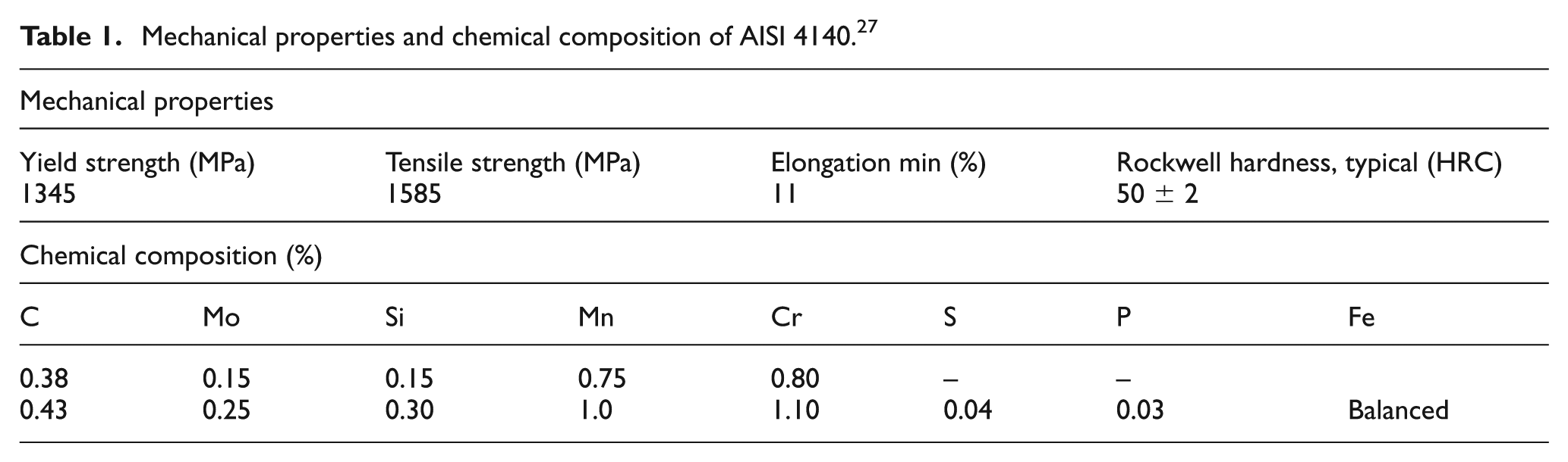
The cutting tools were cubic boron nitride (CBN) inserts (BNX20 grade) from Sumitomo Company. The features of this grade are as follows: extremely high thermal-resistant binder material, excellent wear resistance and toughness at high cutting speeds and suitable for cutting of hardened steels (HRC 45-68). 28 The geometry of the inserts is SNMG 12 04 08 based on International Organization for Standardization (ISO) insert nomenclature. All the inserts had similar geometry with zero obliquity and without chip break.
Ultrasonic equipment
In order to apply one-dimensional vibration to the tool, a 400-W transducer was attached to a horn. In addition, to design the horn, modal analysis was conducted using finite element method (FEM) with regard to the transducer and horn system, which have longitude vibration mode in 27 kHz. The horn is usually designed to have maximum amplitude at the tip to provide sufficient amplitude for machining. This amplification of tool vibration is achieved by reducing the cross section along with the length of the horn. The common profiles of horns for amplifying the output of the transducer are stepped, conical and exponential. In this research, several sets of transducer and horn with different horn shapes were applied. The results showed that contracting horn causes higher vibration amplitudes at the tool tip. The assembly of transducer, horn and their dimensions are shown in Figure 1(a). The results of modal analysis showed that vibration amplitude is 0 at two points. Therefore, displacement for these points is 0 as shown in Figure 1(b). The first zero-amplitude point (node) is located between two piezoelectrics. This positioning reduces stresses on piezoelectrics and increases their lifetime. The second zero-amplitude point (node) is placed in the middle of horn. Thus, this position is the best location for clamping of horn to the dynamometer. Moreover, the insert was clamped at the antinode of the horn tip where the highest amount of amplitude is expected. Figure 2(a) shows tooling setup for UAT. The horn was made from steel to decrease the deflection of the insert tip under vibration and cutting loads. Nest of the insert on the horn end had a 5° relief angle and 45° cutting edge angle. A 1.5-kW and high-frequency (20–30 kHz) ultrasonic power supply was employed to vibrate transducer in ultrasonic frequency range (27 kHz). The horn was designed in a contracting shape, in a manner that produces longitudinal vibration with the frequency of 27 kHz. A PU-09 gap sensor, an AEC-5509 converter and an oscilloscope were used to measure vibration amplitude of the tool tip. The measured values of vibration amplitudes for different ultrasonic powers are 6 and 8 µm (0 to peak amplitude), respectively. The measuring vibration amplitude and actual machining process are illustrated in Figure 2(b) and (c).
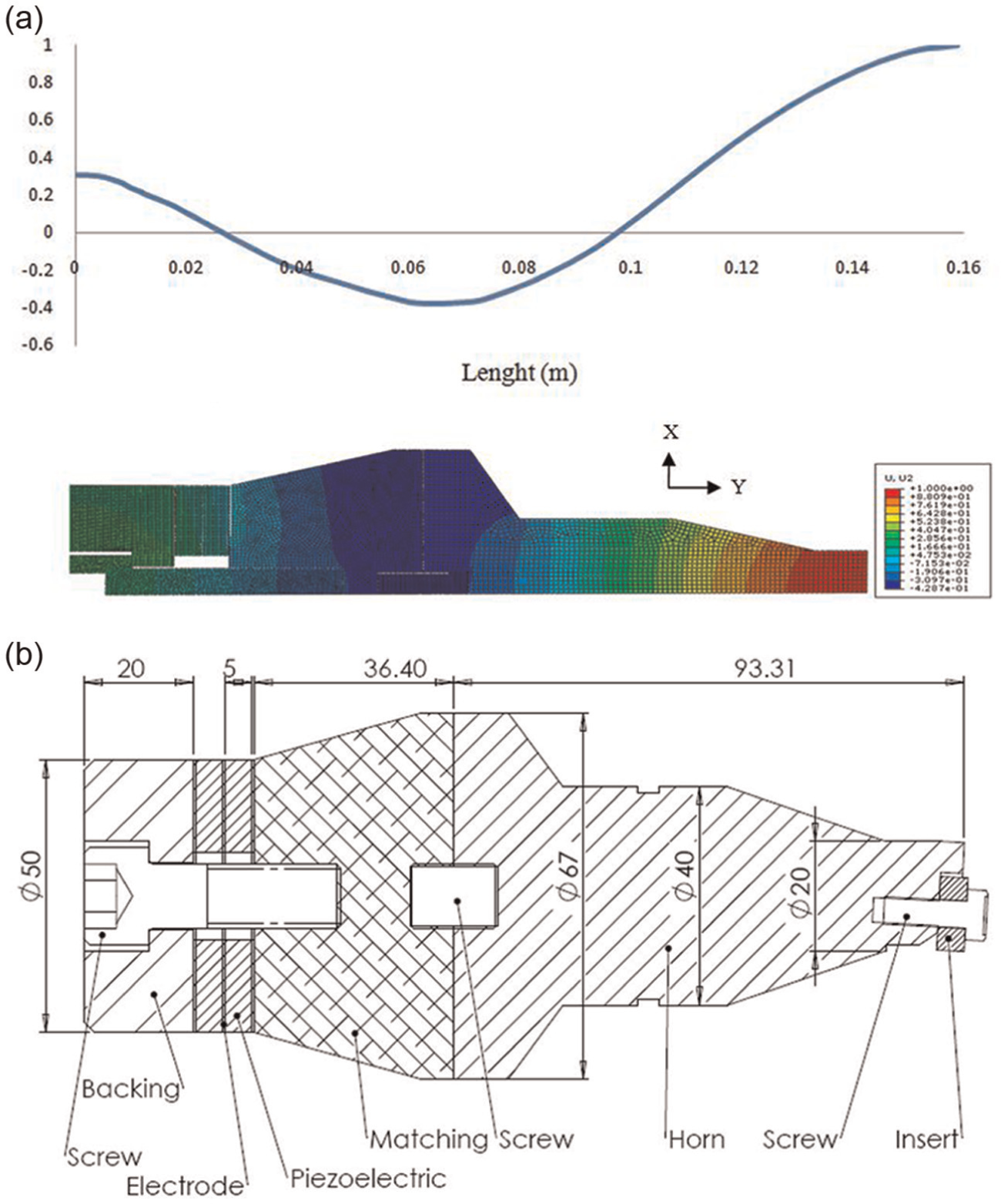
(a) Results of modal analysis with suitable mesh shape in FEM software and (b) assembly of transducer and horn dimensions.
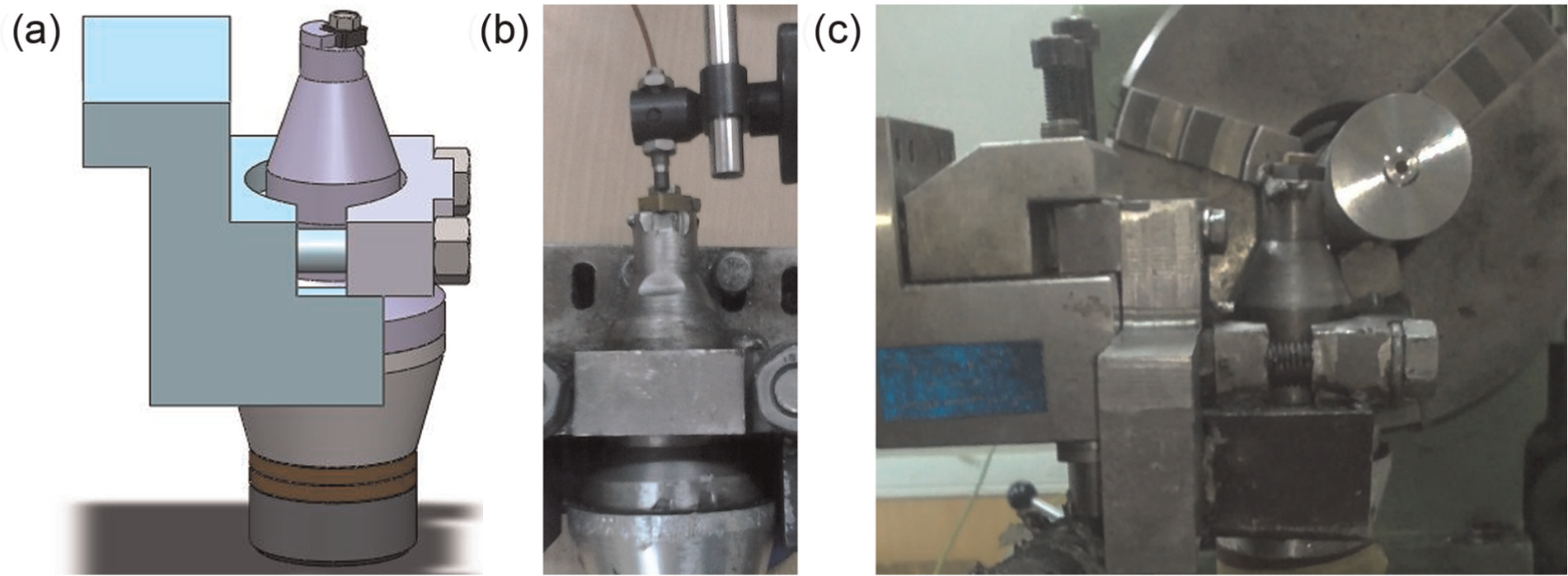
(a) Tool fixture design, (b) vibration amplitude measurement and (c) actual setup for UAT.
Experiment design and measurement
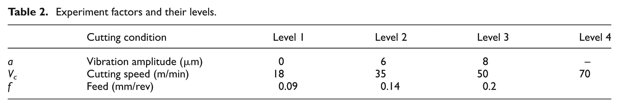
In order to implement the experimental tests, full factorial design of experiments was used (36 sets of experiments) based on two turning parameters (feed and cutting speed) and the vibration amplitude. Some primary experiments according to Sumitomo Company technical guidance were done to find a suitable range for turning parameters. According to the experiments, four levels of cutting speed and three levels of feed were selected. The levels of these parameters are presented in Table 2. The levels of cutting speed were chosen so that they would be smaller than Vcrit in UAT. A constant depth of cut (0.2 mm) was also applied in finishing process of hard turning. To measure the surface roughness (Ra), Taylor Hobson Surtronic 3+ was used. Each test was repeated three times while the surface roughness and cutting force were measured. In each test, surface roughness was measured at three different locations and the average value was calculated.
Experiment factors and their levels.
In order to measure the cutting forces, Kistler 9121 dynamometer was employed. The ultrasonic vibratory tool was installed on the Kistler dynamometer, as shown in Figure 2(c). In order to compare conventional turning (CT) and UAT cutting forces, UAT was performed for about 8 mm and then ultrasonic vibration was turned off, and convectional turning was continued. The drop in cutting force due to UAT can be seen clearly in Figure 3. The highest sampling frequency of Kistler 9121 dynamometer is 20 kHz. Since the frequency of sampling rate is lower than the frequency of ultrasonic vibrations, a moving average signal is recorded, as shown in Figure 3.
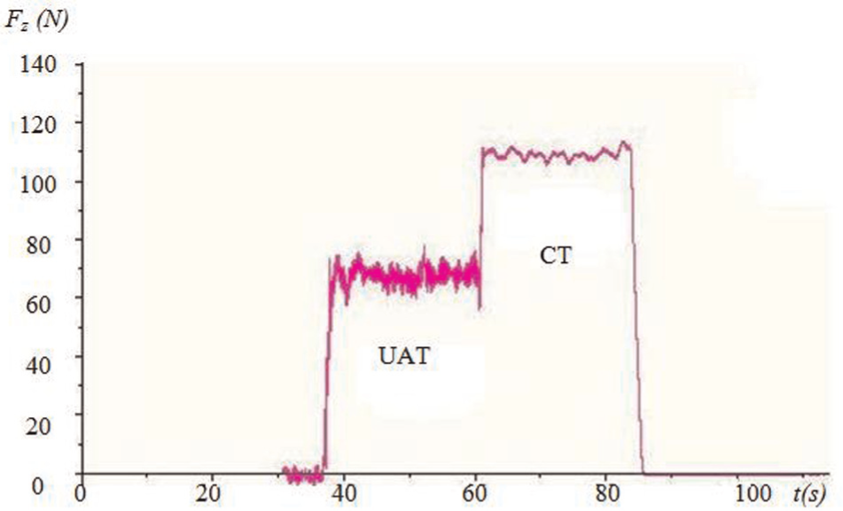
Cutting force measurement by Kistler dynamometer (Vc = 35 m/min, f = 0.14 mm/rev and a = 8 µm).
Experimental results
The results of longitudinal turning tests were used to evaluate machinability of the hardened steel by UAT. The machinability parameters are cutting force (Fz) and surface roughness (Ra). The effects of UAT parameters on cutting forces and surface roughness are investigated in the following sections.
Effect of UAT parameters on Fz
To study the effect of UAT parameters (V, F and a) on cutting force (Fz), a sensitivity analysis is carried out. The analysis of variance (ANOVA) was performed for cutting force (Fz) by means of Minitab software for a significance level of 5%. The results of statistical analysis are presented in Table 3. The sensitivity of cutting force with respect to the above parameters is illustrated in the last column of Table 3. It indicates the degree of influence of each parameter on the results. It can be seen that vibration amplitude of 50.8%, feed of 35.6% and interaction between the cutting speed and the vibration amplitude of 11.4% are the significant factors.
ANOVA for Fz (N).
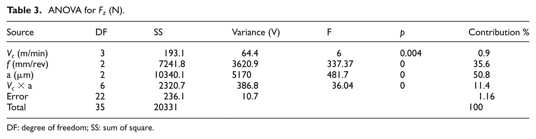
DF: degree of freedom; SS: sum of square.
Figure 4(a)–(c) illustrates the relationship between cutting force and UAT parameters. It can be seen that Fz increases when feed is increased, due to the increase in the chips’ removal ratio from the workpiece material. Cutting force decreases with an increase in vibration amplitude. According to equation (1), cutting takes place only when the tool is engaged with workpiece for a certain fraction of time during each vibration cycle. Therefore, the cutting force can theoretically be considered as low as 0 during tool–workpiece separation periods. The tool is considered to be in contact with the workpiece when the forces are non-zero. The TWCR is defined as the fraction of each cycle spent for cutting. 12 Therefore, the average UAT cutting force is approximated by multiplying the conventional cutting force by the TWCR.
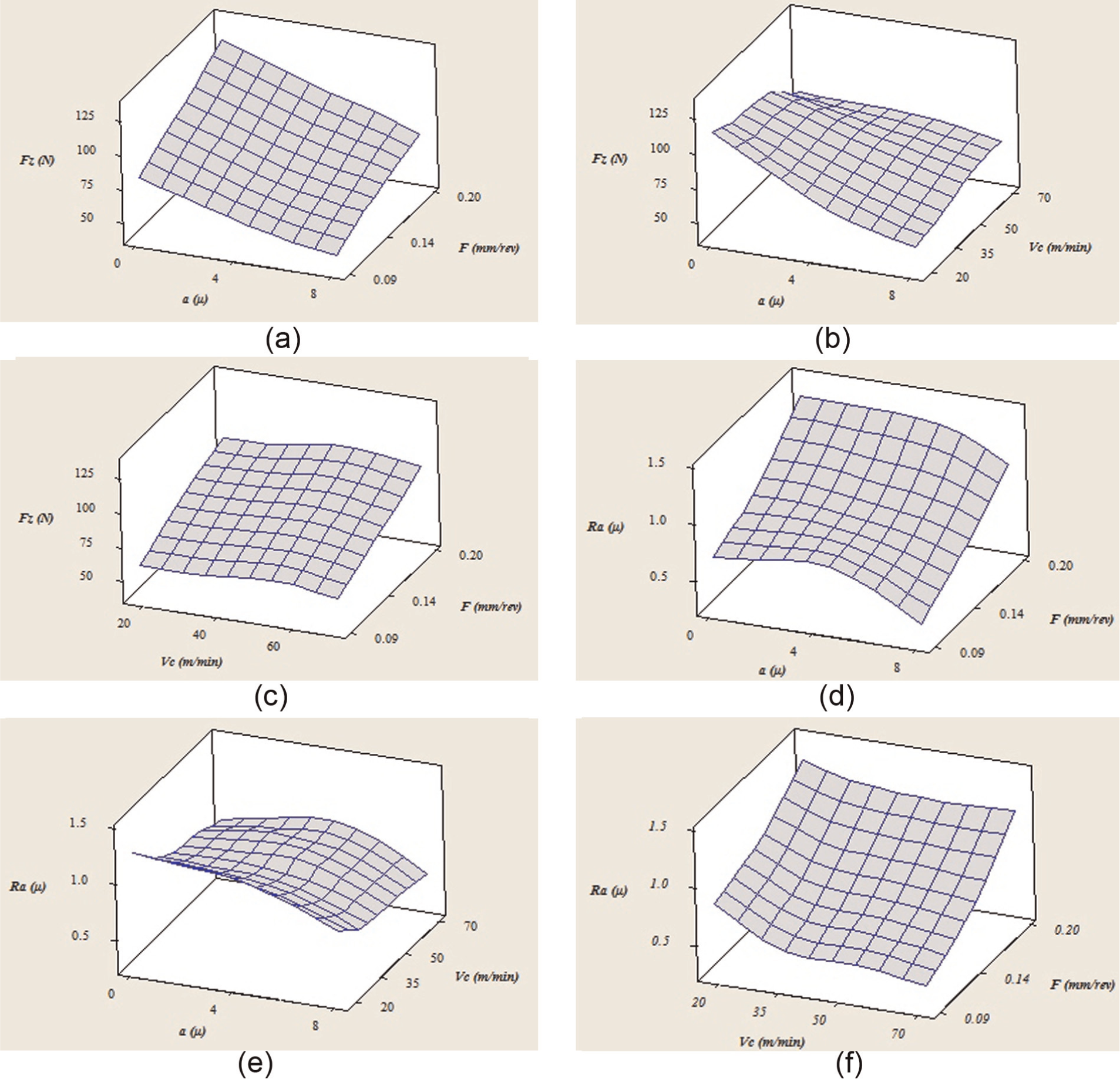
(a–c) Relationship between cutting forces and experiment factors and (d–f) relationship between surface roughness and experiment factors.
The TWCR can be expressed as
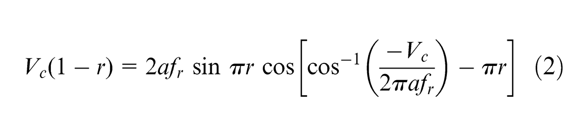
where r is the TWCR. If cutting speed is lower than critical speed shown in equation (1), then tool is not in full contact with the workpiece for the whole period of each cycle. Therefore, TWCR can take a value between 0 and 1. Moreover, the amount of TWCR can be reduced if the vibration amplitude is increased. Any reduction in TWCR can also reduce cutting force. In addition, to decrease TWCR, we can reduce the cutting speed as well. Therefore, it can be concluded that the average cutting force of UAT is less than CT method when appropriate cutting and vibration conditions are considered.
In addition, the vibro-impact cutting condition can reduce friction coefficient due to semi-static and dynamic state of surface interaction in the cutting zone. A reduction in friction coefficient during vibro-impact and dynamic state of cutting zone is expected to reduce friction force and subsequently average cutting force. Therefore, ultrasonic vibrations can be utilized to reduce the cutting force (Fz), by controlling cutting speed below the critical value.
Effect of UAT parameters on Ra
Effect of UAT parameters on surface roughness is listed in Table 4 using ANOVA method. The ANOVA for Ra shown in Table 4 indicates that contributions of feed, vibration amplitude and cutting speed are 67.3%, 14.2% and 13%, respectively. The effect of feed is significant among other parameters. Figure 4(d)–(f) shows the relationship between Ra and UAT parameters. As shown in Figure 4(d), the roughness increases if the feed is increased respectively. Turning at low feed usually leads to generate low surface roughness. The surface roughness is improved by increasing the vibration amplitude and decreasing the cutting speed. In other words, a lower TWCR is expected at lower cutting speed and higher vibration amplitude. Smoother surface and cutting overlaps can be achieved by reducing TWCR. Nevertheless, surface roughness caused by tool vibration marks can be improved by increasing cutting overlaps per unit area.29,30
ANOVA for surface roughness Ra (µm).
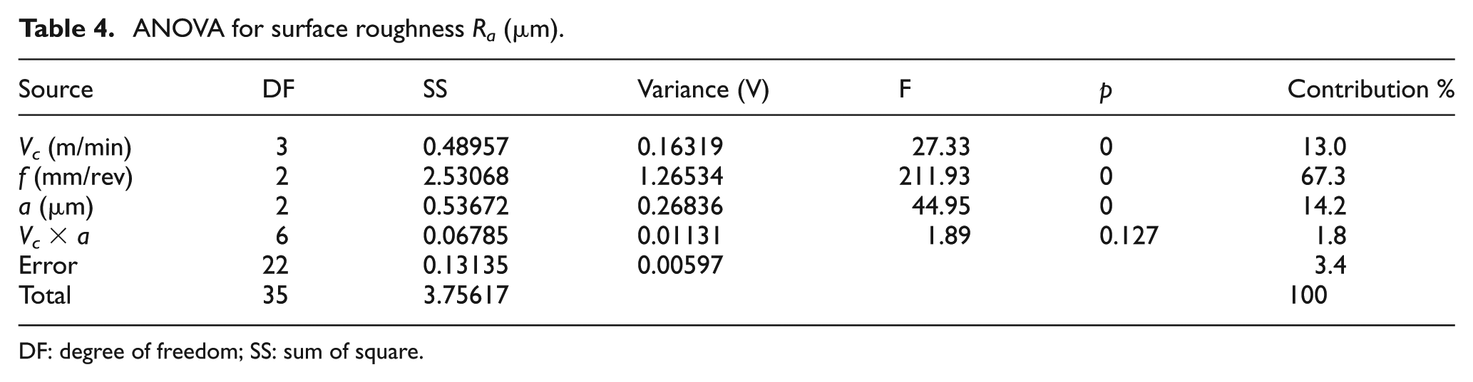
DF: degree of freedom; SS: sum of square.
While the Vc increases and approaches to Vcrit, the effect of ultrasonic vibration on the process slightly reduces. Tool vibration marks are commonly seen on workpiece surface due to tools’ vibro-impact cutting movements backward and forward. The surface roughness decreases if tool vibration marks on workpiece surface get closer and denser, as shown in Figure 5, for medium level of feed (0.14 mm/rev) and low level of cutting speed (18 m/min). However, by increasing the cutting speed, distance between the vibration marks is increased. This will increase the surface roughness, which will approach its value that is usually seen in CT process.
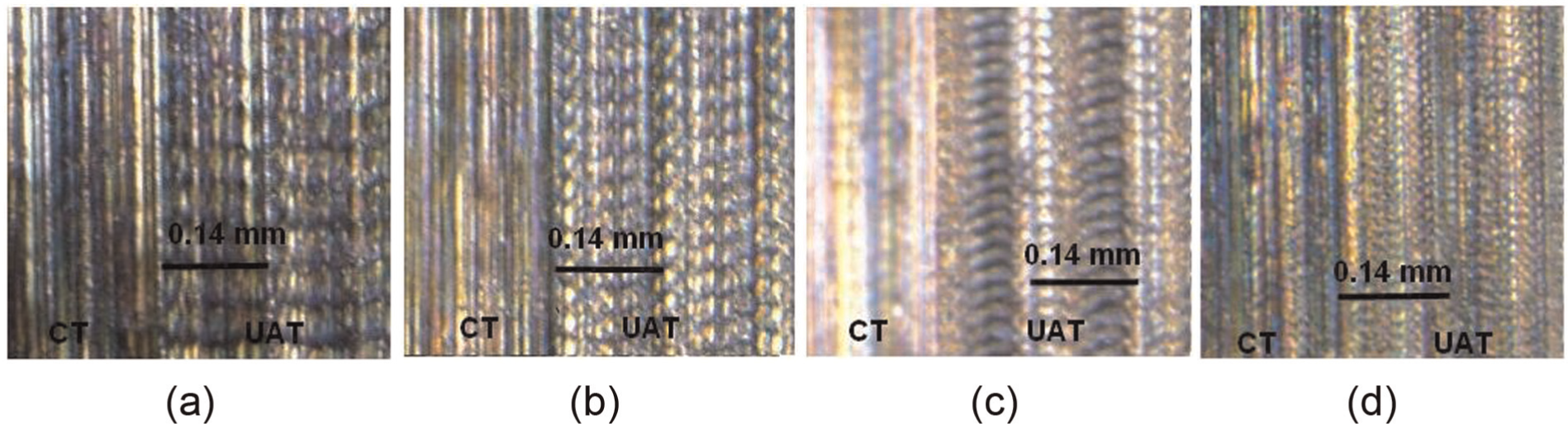
Workpiece texture at different cutting speeds in UAT: (a) Vc = 70 m/min, (b) Vc = 50 m/min, (c) Vc = 35 m/min and (d) Vc = 18 m/min.
Optimization methodology
Description of EMA
In recent years, EMAs have been extensively employed in optimization problems. For the first time, Birbil and Fang 22 introduced this method, to solve continuous optimization models. This method is based on attraction and repulsion forces between charged particles and is designed for optimizing non-linear, real-valued problems. The algorithm is a population-based algorithm similar to GA. An initial population should be generated in the first stage of the algorithm. Each point is considered as an electromagnetic-like charged particle that can influence other particles. The charge of each point is calculated based on its objective value. The force field of each point causes other points to move toward the force vector. Points with better objective value attract neighboring points to converge to that point, while worse ones repel them away. This approach creates an intelligent search field in solution space. Generally, this method is implemented in three main steps. The steps of this method consist of initial population generation, computing total force and computing vector movement according to the previous stage. The complete explanation for EMA steps and their procedures can be found in Chang et al. 31 and Naderi et al.; 32 the summary of the procedure is explained in the following.
The relationship between the particles’ charge and the objective function is described in equation (3)
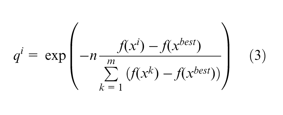
where
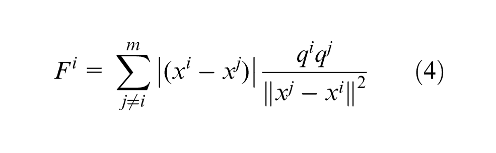
The particles move to a new position in the resultant force direction according to equation (4). This movement is calculated as follows in equation (5)
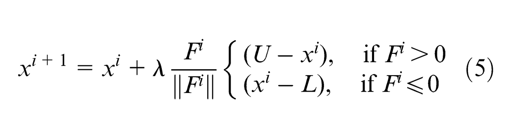
where U and L are the upper and lower bounds of coordinates of the particle position vector. For assurance of non-zero probability in movement of particles to the entire space of solution,
Penalty function technique for constraint-handling optimization
Optimal solution is typically found on the boundaries of solution domain, which is applied for constrained optimization problems. Therefore, the problem may be easily converted into an unconstrained situation in which a penalty function is added to the objective function in the case of constrained optimization. In the present approach, a penalty term penalizes the constraint violation of the problem. This technique has been successfully used to find optimum solution in constrained problems. 33 In order to remove constraints from a problem, a newly defined fitness function, F(x), should be optimized. This function is defined as follows 34
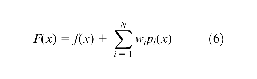
where wis are the penalty numbers, Pi(x)s are the penalty constraints and f(x) is the initial objective function.
Many researchers in iterative computation of objective functions have explored variations in distance-based static penalty functions. 26 Gen and Cheng 33 have presented an early review of penalty functions in GAs. According to their investigations, the values of penalty function should be comparable to the values of the objective function.
Using NN for modeling surface roughness and cutting force
In order to determine constraints in optimization problem, two functions should be created to predict process outputs. An artificial neural network (ANN) model for surface roughness and a model for cutting force were built in two phases based on back-propagation network learning algorithm (BPN). In the first phase of BPN regarding experimental data, neurons characteristics including threshold values and weight are updated. This phase is named the training process. In the second phase, in order to achieve the prediction capability, the updated weights and threshold’s values were recalled. 14
The number of layers and neurons in each layer has great influence on the performance of ANN. In this research work, several combinations of layers and neurons were examined. As a result, ANN structure with six neurons in the first layer and with four neurons in the second layer was used. Other ANN specifications can be found in the literature. 20
About 85% of experiments (31 data) were chosen for training with the Levenberg–Marquardt algorithm, and 15% of experiments (five data) were included in the testing stage. The error values in Table 5 confirm that ANN model with mentioned characteristics has the acceptable ability to predict desire process outputs.
Results of ANN tests.
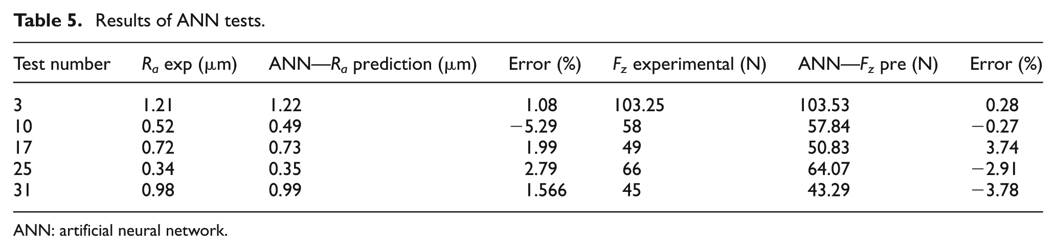
ANN: artificial neural network.
Objective and constraints
To find the optimal UAT parameters leading to the maximum MRR and to satisfy surface roughness and cutting force constraints, a set of objective function and constraints should be defined. The MRR in turning operations is the volume of the material removed per unit time (mm3/min). For each revolution of the workpiece, a ring-shaped layer of material is removed.
In order to present the constrained optimization, a new fitness function (−MRR, the minus sign indicates finding the maximum of MRR in the optimization process) was optimized. Constraint function (−MRR) illustrates the combination of the objective function MRR and weighted NN terms, Pi(x) which were defined as penalty values for violation of the constraining functions
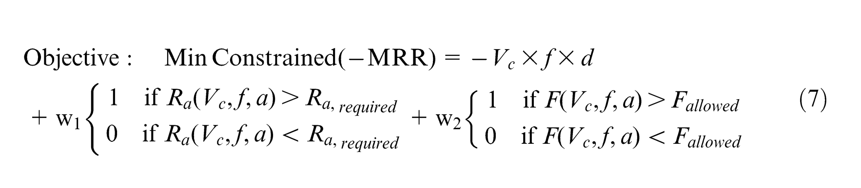
where d is the depth of cut (mm) and MRR is the material removal rate (mm3/min). The allowable ranges of UAT conditions are as follows

The maximum required Ra and the maximum allowable values for cutting force, as the constraints of the model, should be selected according to part and dimensional requirements mentioned in the engineering drawings.
Numerical example
To examine the effectiveness of constrained optimization by EMA, a practical problem in turning process was investigated.
Defining the problem
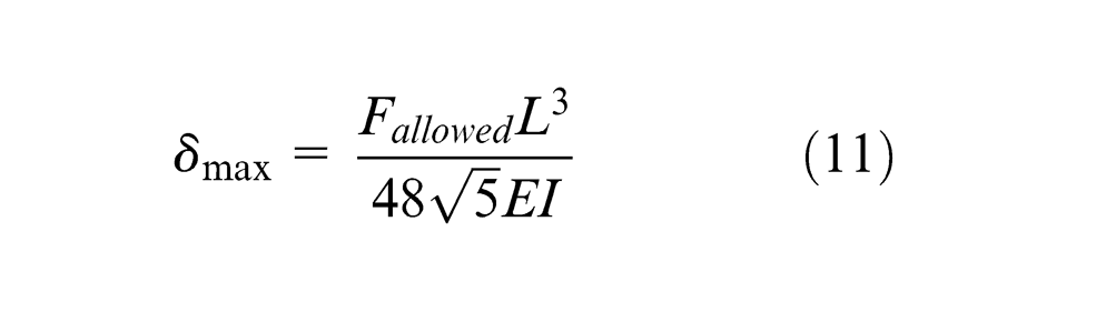
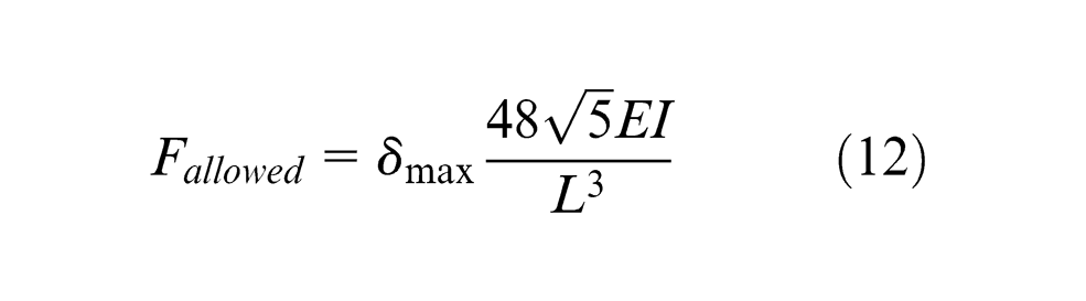
As a case study, experimental UAT was conducted in order to produce an aerospace industrial shaft. According to customer requirements, the part should be machined by the required surface roughness, while its cylindrical dimension should be kept within the allowed tolerance. The type of chucking of workpiece in turning operation was three-jaw chuck with center support (see Figure 6). The equations for maximum deflection (
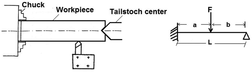
Turning operation (left) and workpiece model (right).
where F is the load (N), L is the length of the workpiece (mm), E is the modulus of elasticity (N/mm2) and I is the moment of inertia of parts’ cross sections (mm4). The moment of inertia of a round bar is I = 0.049D
4. The allowable value for deflection should be controlled by the cylindrical tolerances. As an example, three cylindrical tolerances of 0.03, 0.02 and 0.012 mm were considered. If allowable deflection of the shaft is considered as 40% of cylindrical tolerance of the shaft, then
Optimization by EMA and GA
An optimization code EMA was written in MATLAB and the GA tool box of MATLAB was also employed to solve the constrained optimization problems in equation (7). Several combinations of the assumed factors for turning conditions were studied to achieve the best optimal solutions. The initial EMA and GA parameters should be selected in a manner to accommodate faster convergence of algorithms. Therefore, some preliminary numerical runs have been conducted by the authors. According to the preliminary numerical runs, a double vector and uniform function were obtained as the population type and mutation for GA.
Population size and iterations have notable effects on the quality and effectiveness of the algorithms. Therefore, in order to adjust the parameters, three levels of low, medium and high were selected for each parameter. Three levels of population size and iterations were selected as (10, 20, 30) and (20, 40, 60), respectively. Moreover, several experiments based on full factorial experimental design were carried out.
To compare two algorithms, each test was run 100 times, and the values of mean, minimum, maximum and standard deviation (SD) were recorded. According to Table 6 (for the case of Ra, required = 1 µm and Fallowed = 80 N), it is clear that the results of GA and EMA are in close agreement with each other. Also, the values of the surface roughness and the cutting force are lower than the maximum allowed values. The mean values of MRR show a stable trend of increase with respect to an increase in population size and iteration. EMA method has lower SD and higher minimum values in comparison to GA. EMA leads to higher maximum MRR with less population size and iterations. In order to validate the proposed method, a number of experiments, in the optimal condition, were conducted along with the value comparison of the user constraints with the experimental results. The obtained error values that are shown in Table 7 are in the admissible range. The predicted values and measurements of Ra and cutting force are in close range and less than the maximum admissible values, as shown in Table 7. Nevertheless, the maximum admissible cutting force is limited to low levels of cutting parameters (Vc and f) and high level of vibration amplitude. In these cases, the obtained surface roughness is acceptable and below the required surface roughness. Also in those cases where surface roughnesses are preferred to be lower, the cutting force also is lower than the allowed values. In fact, the optimization method has selected the cutting condition in a manner that satisfies all constraints.
Comparison of EMA and GA.
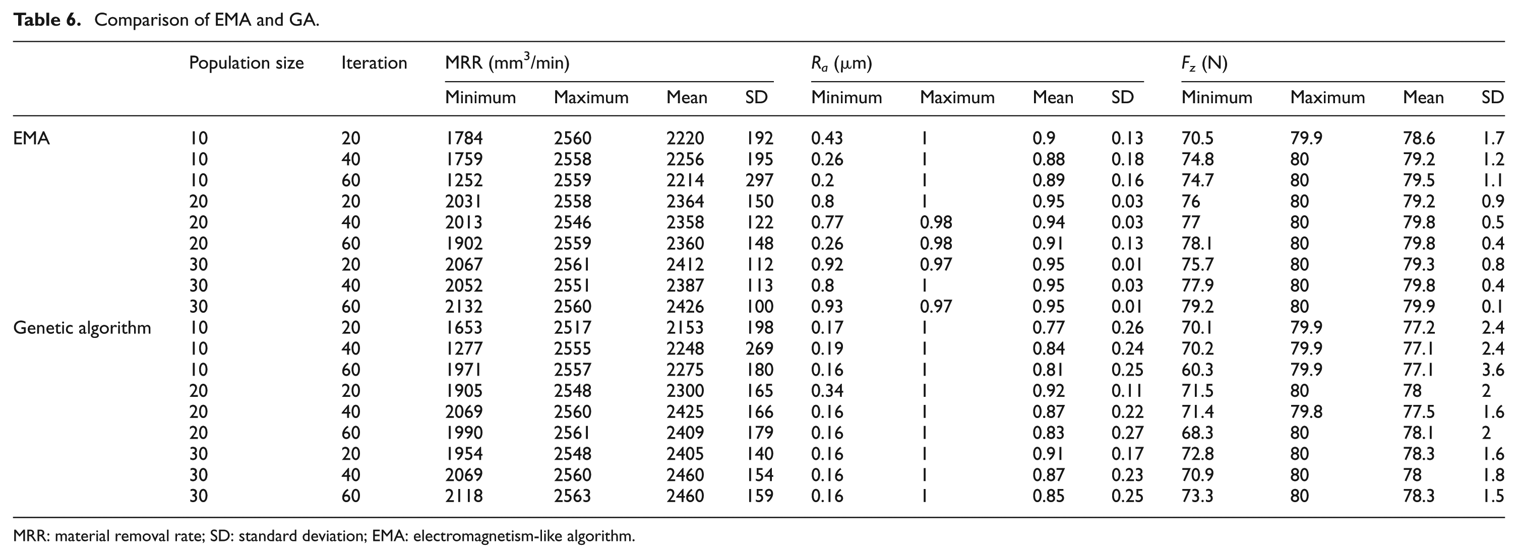
MRR: material removal rate; SD: standard deviation; EMA: electromagnetism-like algorithm.
Results of the validation test.
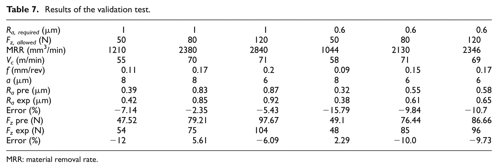
MRR: material removal rate.
Conclusion
A methodology is proposed to optimize UAT process during machining of hardened steel AISI 4140. NN was employed to model process outputs (surface roughness and cutting force). The following conclusions can be drawn from constrained optimization of UAT process. Contributions of the feed and vibration amplitude to keep cutting force below allowable value were observed to be 35.6% and 50.8%, respectively. More reduction in cutting force was observed during UAT process when a higher vibration amplitude and lower level of cutting speed were applied. Contributions of the feed, vibration amplitude and cutting speed to reduce surface roughness below the admissible value were obtained to be 67.3%, 14.2% and 13%, respectively.
Improved surface roughness in UAT occurs when a high level of vibration amplitude is used in conjunction with low level of cutting speed. In this study, a penalty method was adopted to convert constrained optimization problem to the unconstrained problem. Back-propagation artificial NNs were successfully incorporated into modeling of constrained optimization problems. Application of EMA to optimize machining parameters has proved to be more effective in comparison to GA. Constrained optimization results showed that if low levels of cutting forces are ideally required, then low levels of cutting speed and high level of vibration amplitude should be used. In these cases, the surface roughness is predicted to be below the maximum admissible surface roughness. Similarly, lower surface roughness can ensure lower levels of cutting force. This optimization method has been able to select the cutting parameters in order to satisfy all optimization constraints.
Footnotes
Appendix 1
Declaration of conflicting interests
The authors declare that there is no conflict of interest.
Funding
This research received no specific grant from any funding agency in the public, commercial, or not-for-profit sectors.