
Abstract
To experimentally investigate the forming behavior of automotive high-strength steel sheets under electromagnetic pressure, three high-strength steel sheets (DP780, DP980, and CP1180) were freely formed into hemi-elliptical protrusions. The experiments were performed using a spiral flat coil and open-cavity die. Aluminum driver plates were utilized for improving the forming efficiency. The forming behavior was investigated by evaluating characteristics such as peak height, limit height, and springback angle for various charge voltages. The effect of the aluminum driver plate on the forming behavior of the high-strength steel sheet was also observed.
Keywords
Introduction
Electromagnetic forming is a high-speed manufacturing process that uses pulsed electromagnetic pressure to deform tubular or sheet metal workpieces.1–5 During this process, high-density electric current passes through a conductive coil by discharging a capacitor back and produces a transient magnetic field that induces eddy currents in a nearby metal sheet. The mutually repulsive electromagnetic pressure resulting between the stationary coil and the metal sheet can deform or accelerate the latter. Electromagnetic forming offers several advantages over convention metal forming and is fundamentally different from traditional quasi-static forming. The high velocity can significantly increase the formability6–8 and reduce the springback and wrinkling of metal sheets. 2 Additionally, the contact-free application of force eliminates the need for the male punch and lubrication, thereby significantly reducing the cost.
Depending on the arrangement and geometry of the coil and workpiece, the following electromagnetic forming applications are possible: (a) compression and expansion of tubular components or hollow profiles and (b) forming of initially flat or three-dimensional preformed sheet metals. The process can be used for joining and deforming similar and dissimilar flat or tubular metal sheets.
The use of high-strength steel sheets in the production of body-in-white parts9,10 has remarkably increased owing to the need to reduce the weight of automobiles for improving their fuel consumption. Furthermore, the application of ultra-high-strength steel sheets with tensile strength above 1 GPa has recently expanded as greater sheet strength has become necessary for satisfying the safety standards for automobiles.
Studies on the forming behavior of high-strength steel sheets during the electromagnetic forming process are fewer than the studies on that of aluminum alloy sheets. Seth et al. 6 investigated the formability of steel sheets using electromagnetic forming using a spiral flat coil. Kamal and Daehn 11 examined the effect of material conductivity on electromagnetic forming efficiency by comparing the extent of deformation of copper, aluminum, and auto-grade steel sheets. Iriondo et al.12,13 used electromagnetic forming to calibrate the shape distortion after the springback of high-strength steel sheets. Kim et al. 14 numerically analyzed the electromagnetic forming of low-carbon steel sheets using sequential coupled electromagnetic–mechanical simulations.
Studies on the electromagnetic forming of high-strength steel sheets with tensile strength lower than 780 MPa have been conducted recently, and its potential to form shallow longitudinal reinforcement ribs in the lateral walls of roll-formed parts made of steel sheets of 340 MPa tensile stress grade has been studied.2,15 However, examining the behavior of high-strength steel sheets of higher tensile stress grade proves to be challenging because of their higher tensile strength and lower conductivity. Moreover, the use of aluminum driver plates might be considered for enhancing the degree of forming of high-strength steel sheets through the electromagnetic forming process. To comprehend the possibility of using high-strength steel sheets to form the reinforcement ribs of automotive parts through the electromagnetic forming process, it is important to investigate (a) the behavior of these sheets during the forming of hemi-elliptical protrusion shapes similar to shallow longitudinal reinforcement ribs and (b) the effects of the aluminum driver plate on the forming behavior.
In this study, therefore, we focused on evaluating the forming height and extent of springback of high-strength steel sheets with and without aluminum driver plates when subjected to the electromagnetic forming process. For experimentally investigating the forming behavior of automotive high-strength steel sheets of over 780 MPa tensile stress grade under electromagnetic pressure, three high-strength steel sheets (DP780, DP980, and CP1180) were freely formed into hemi-elliptical protrusions. Experiments were conducted using a spiral flat coil and open-cavity die. In view of the fact that deforming a high-strength steel sheet workpiece on account of its low electric conductivity, high magnetic permeability, and therefore poor electromagnetic forming efficiency, an aluminum driver plate was used for improving the forming efficiency. The forming behavior was examined by studying the characteristics such as peak height, limit height, and springback angle for various charge voltages. The effect of the aluminum driver plate on the forming behavior of the steel sheet was also observed.
Experiments
Materials
The high-strength steel sheets for automotive applications (used in the experiments) were provided by POSCO. Two dual-phase steel sheets (DP780 and DP980) with thicknesses of 1.0 and 1.4 mm, respectively, and one complex-phase steel sheet (CP1180) with thickness of 1.2 mm were utilized in this study. The dual- and complex-phase steel sheets were composed of ferrite and martensite and a complex phase of ferrite, bainite, and martensite, respectively, to enhance their strengths. The optical microstructures of the three steel sheets are shown in Figure 1. As mentioned earlier, the high-strength steel sheet does not deform effectively under electromagnetic pressure during the forming process because of its poor electrical conductivity. The aluminum driver plate, owing to its higher conductivity, is expected to induce higher currents and have lower rise time (time to achieve peak current) than high-strength steel sheets. Additionally, as the magnetic flux density between the plate and coil is larger, a higher magnetic pressure acts on the aluminum driver plate than on the steel sheet. Thus, the aluminum driver plate aids the more effective deformation of the high-strength steel sheet workpiece. In this study, the A1050-H16 aluminum alloy with 1.0 mm thickness was used as the driver plate. The chemical compositions of all the materials are summarized in Table 1. The flow curves obtained from the quasi-static tensile test are shown in Figure 2, and the relationship between true stress (

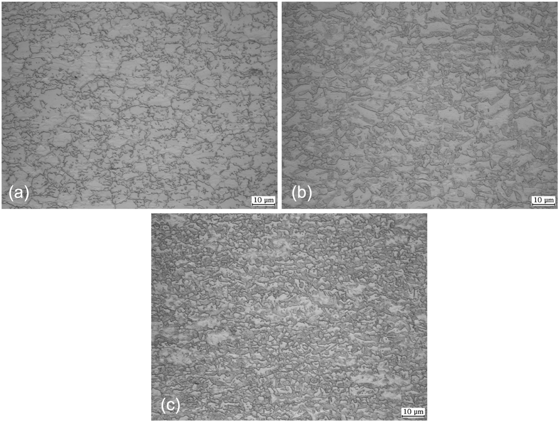
Optical microstructure of steel sheets: (a) DP780, (b) DP980, and (c) CP1180.
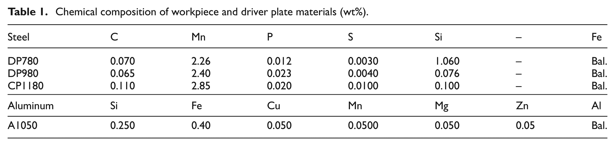
Chemical composition of workpiece and driver plate materials (wt%).
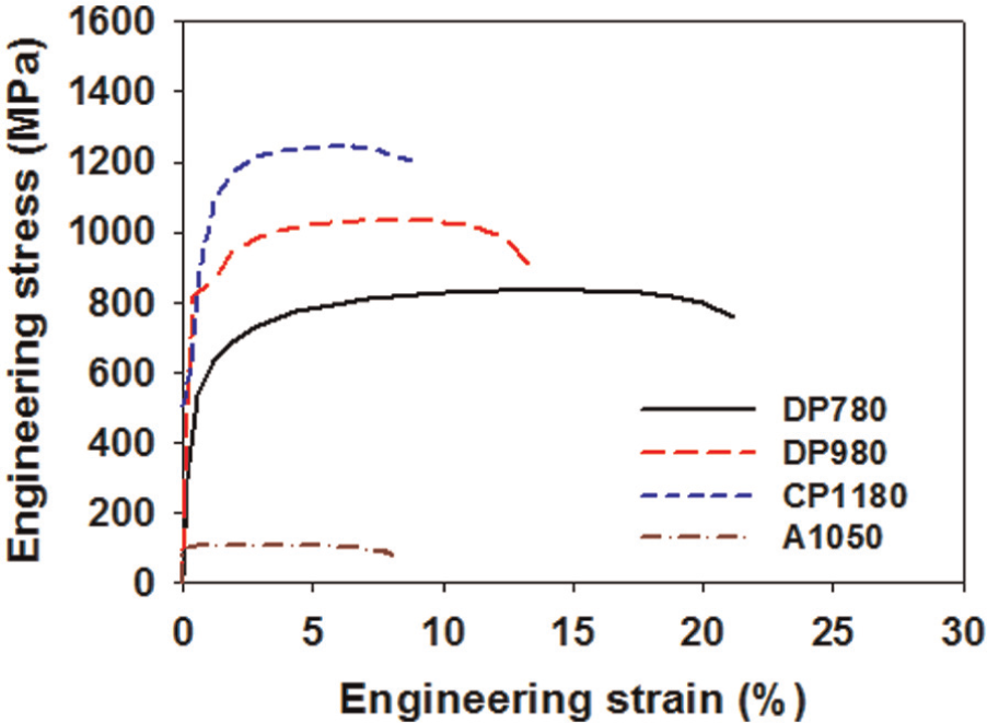
Flow curves of DP780, DP980, and CP1180 high-strength steel sheets and A1050 aluminum alloy sheet.
where
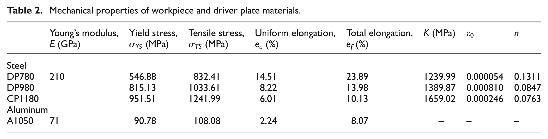
Mechanical properties of workpiece and driver plate materials.
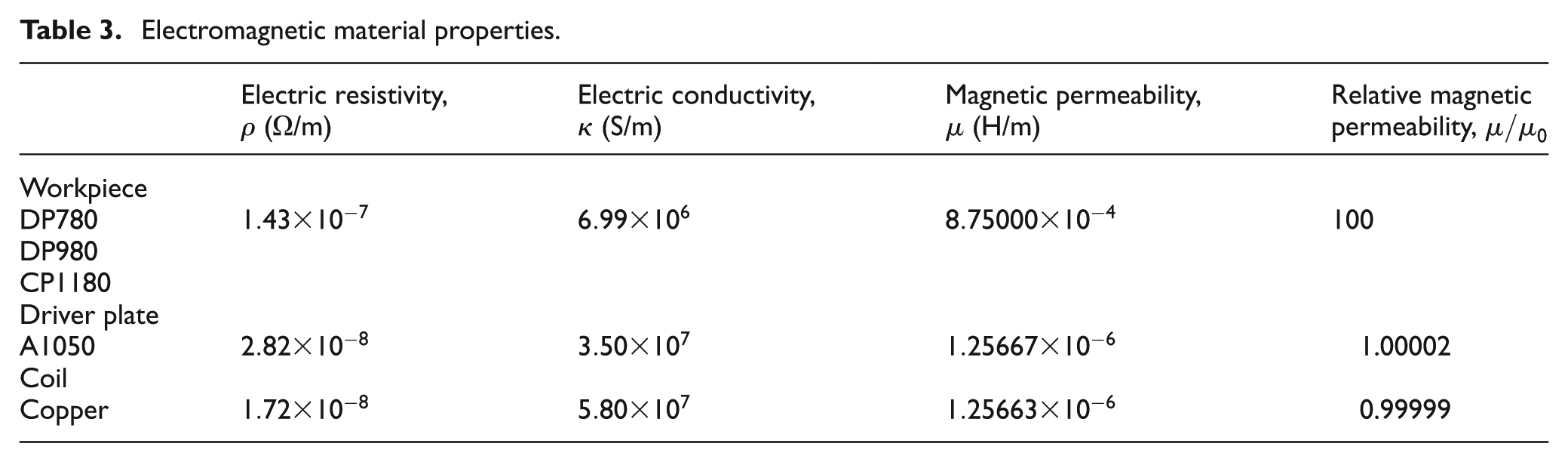
Electromagnetic material properties.
Electromagnetic forming
In this study, a spiral flat coil was adopted for forming the hemi-elliptical protrusion shape using an open-cavity die. Figure 3 shows the configuration and geometric dimensions of the spiral flat coil system in which the hole of the open-cavity die is located near the average coil radius to avoid the “dead spot” zone that occurs at the center of the winding.16,17 The coil was wound from the copper plate with a square cross-sectional area of 25 mm2. The profile of the coil was machined into a reinforcing and insulating block of epoxy that was covered by a thin layer of epoxy film. The blanks of the sheet workpiece were located without or with the driver plate between the insulated coil and the open-cavity die, without any lubricant. The insulated coil was covered with a housing block of machined steel. The coil die tool was connected to the electromagnetic forming system composed of a power supply, capacitor back, and remote controller, as shown in Figure 4. This system had a maximum stored energy of 119 kJ within four capacitors, each with a capacitance of 206 μF. The system had a maximum working voltage of 17 kV, and the charge voltage was varied to control the discharged energy. The primary current profiles were measured using a Rogowski flexible coil probe and an oscilloscope.
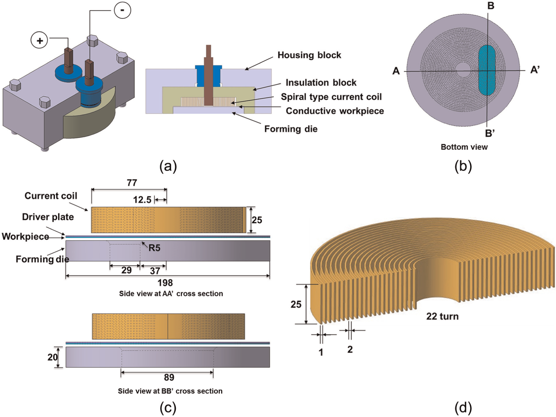
(a) Configuration of spiral flat coil system, (b) bottom view, (c) side view of copper coil and open-cavity die, and (d) dimensions of copper coil (unit: mm).
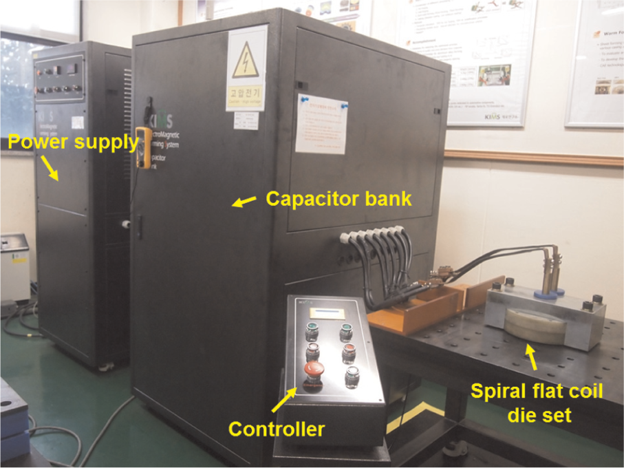
Experimental apparatus.
Successive experiments were performed at increasing charge voltage levels until those associated with the “point of failure” were achieved. After this, two or three samples were formed at lower energy levels and one at a higher level. This sequence provides information about the extent of the deformation in the samples, leading up to the point of failure.
Results and discussion
Current profiles
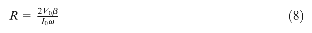
The magnetic pressure and resulting sheet motion can be evaluated using the currents in the primary and induced circuits. The values of the current I can be estimated by analyzing the standard inductance L, resistance R, and capacitance C (through LRC analysis). The ordinary differential equation of the LRC system can be expressed as follows2,11
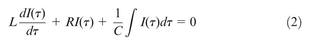
Typically, the LRC circuit for electromagnetic forming is underdamped, leading to oscillations or ringing in the circuit. Therefore, the resulting current is a highly damped sinusoidal oscillation. The solution of equation (2) yields the current as a function of the time

where
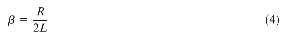
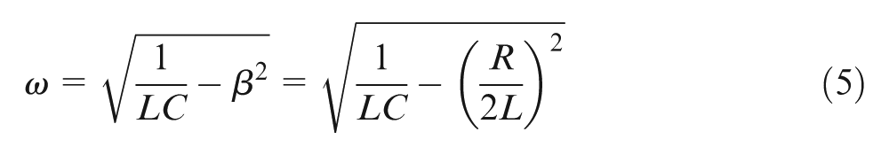
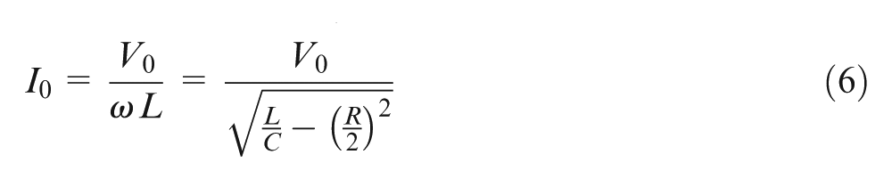
here,
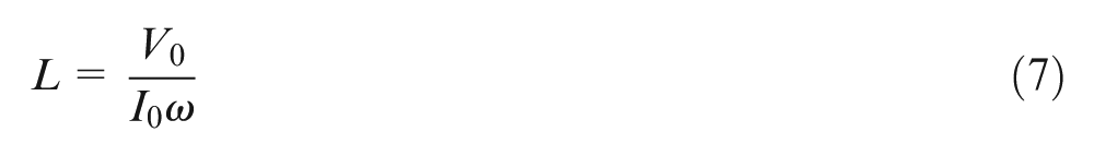
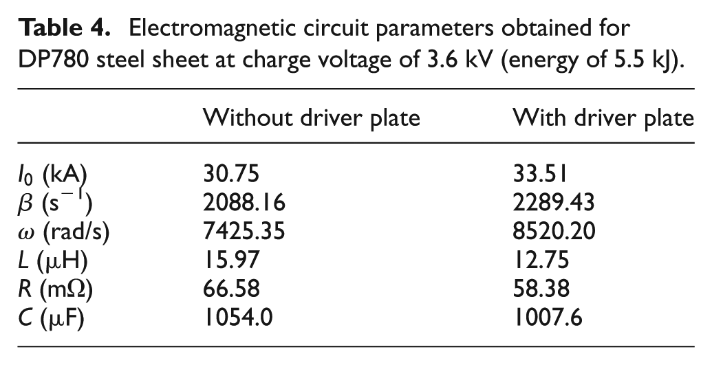
The circuit parameters can be estimated by measuring the profile of the discharge current for a given charging voltage and fitting it with equation (3). For inverse characterization of the circuit parameters, the discharge current densities of the DP780 sheet workpiece without and with the A1050 driver plate were measured for a charging voltage of 3.6 kV. The current profile was fitted using the analytical solution given in equation (3) by adopting the least square method. Figure 5 compares the measured and fitted profiles of the primary currents, and the obtained circuit parameters are listed in Table 4. The obtained C of the system is observed to be different from the specified C due to fitting errors, owing to the simplicity of equations (2)–(9), which, for instance, ignore the mutual L between the coil and the workpiece. However, if the specified C is considered instead of the specified voltage in equations (7)–(9), the input (or specified) initial voltage will differ from the fitted (or measured) value. The circuit parameters for the formed high-strength steel sheets without the driver plate were slightly different from those for the formed aluminum sheets with the driver plate because the primary current profile in the former case was affected by the eddy current induced within the high-strength steel sheets. A change in the magnetic field induces an electric field in a nearby metal sheet, which, in turn, generates an eddy current. This eddy current can be defined as the product of the conductivity of the metal sheet and the electric field. When the same charge voltages are input during forming with and without the driver plate, the induced electric fields become similar to each other and the eddy current is, therefore, proportional to the conductivity. More eddy current will be induced when the aluminum driver plate is used because the conductivity of aluminum is greater than that of steel. The values of the ringing frequency
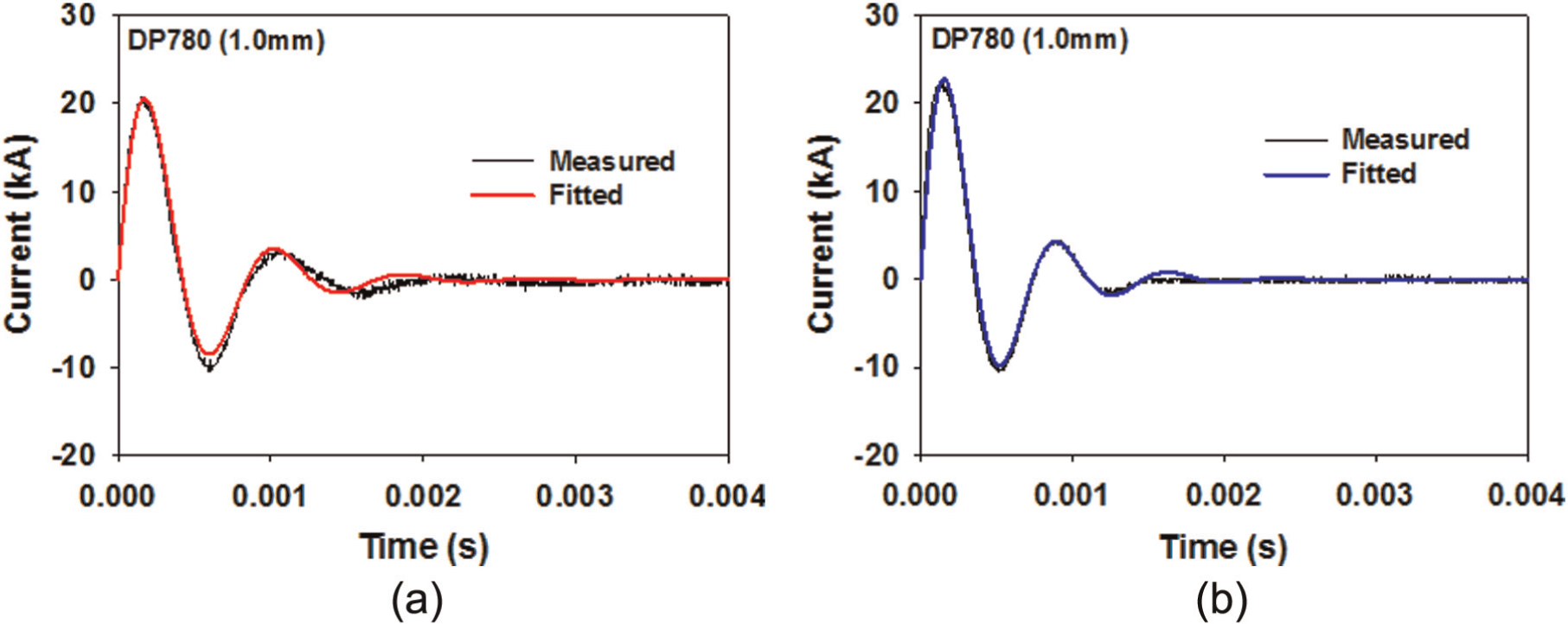
Comparison between measured and fitted profiles of primary current at charge voltage of 3.6 kV for DP780: (a) without and (b) with driver plate.
Electromagnetic circuit parameters obtained for DP780 steel sheet at charge voltage of 3.6 kV (energy of 5.5 kJ).
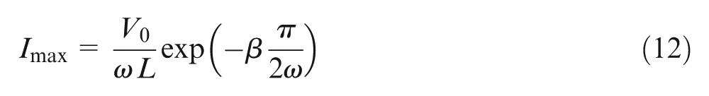
where
For pulsed operation, 4 kA/mm2 is the allowed current density J through a copper conductor, without any overheating of the conductors or mechanical damage. 19 Hence, the required cross-sectional area A of the coil conductor is
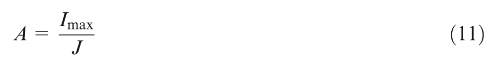
where Imax is the maximum current. The cross-sectional area of the spiral flat coil is 25 mm2, as shown in Figure 3(d). Therefore, Imax should be less than 100 kA. If the first peak current is assumed to occur in the first quarter cycle of a current pulse (when
The available charging voltage should be less than 7.6 kV in the circuit with the spiral flat coil. We used charging voltages of <7.6 kV for all experiments in this study.
Forming behavior
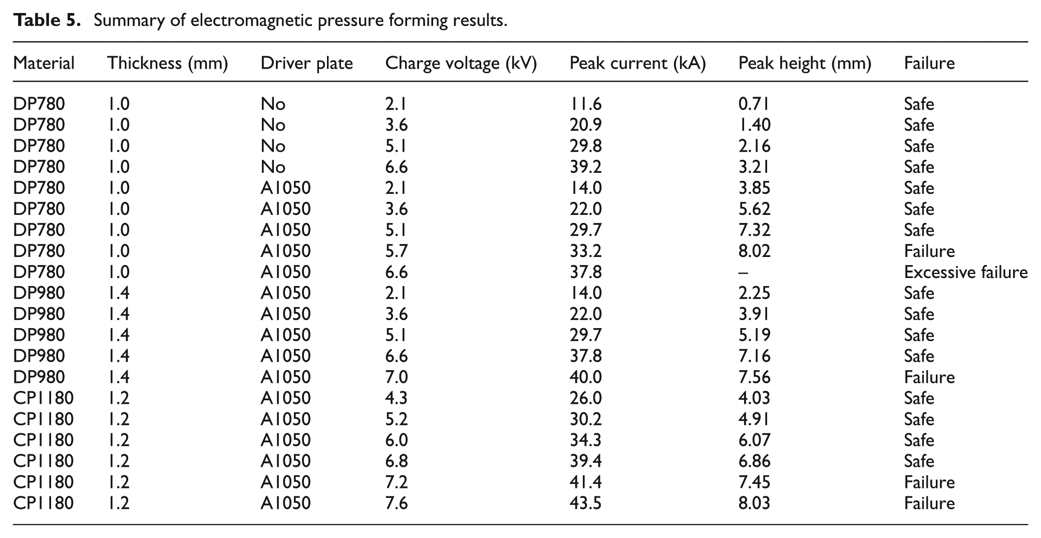
The process conditions and results for all the electromagnetic forming experiments are summarized in Table 5. The typical deformed shapes of the DP780 steel sheets with the aluminum driver plate after electromagnetic forming using the spiral flat coil are shown in Figure 6. The steel sheets are observed to be safely formed without failure at the charge voltage of 5.1 kV, whereas with excessive failure at 6.6 kV. Failure is observed to appear and progress in the corner of the open-cavity die. It may seem that the sheet materials are localized and failure occurred because the surface friction and the bending deformation prevented the flow of the material in the corner of the die. The cross-sectional shapes of the DP780 steel sheet with the A1050 driver plate at the charge voltage of 3.6 kV are shown in Figure 7. The shapes of the high-strength steel sheet and the aluminum driver plate after electromagnetic forming are observed to be very slightly different, implying that the workpiece and driver plate deformed together with close contact. The slight deviation between the workpiece and aluminum driver plate at the flange of the cross-sectional shape is due to the difference in their elastic moduli. The variation in the cross-sectional shape of the DP780 workpiece sheet with the A1050 driver plate with respect to the charge voltage is presented in Figure 8. As expected, the forming height is observed to increase with the increase in the voltage.
Summary of electromagnetic pressure forming results.
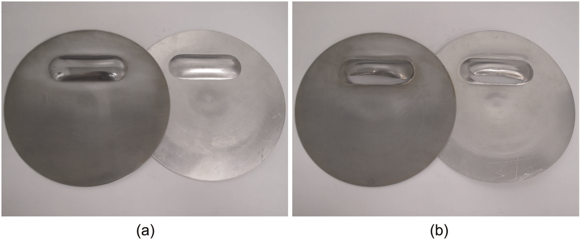
Typical deformed shape of DP780 steel sheets with aluminum driver plates after electromagnetic forming with spiral flat coil at charge voltage of (a) 5.1 kV (safe) and (b) 6.6 kV (excessive failure).
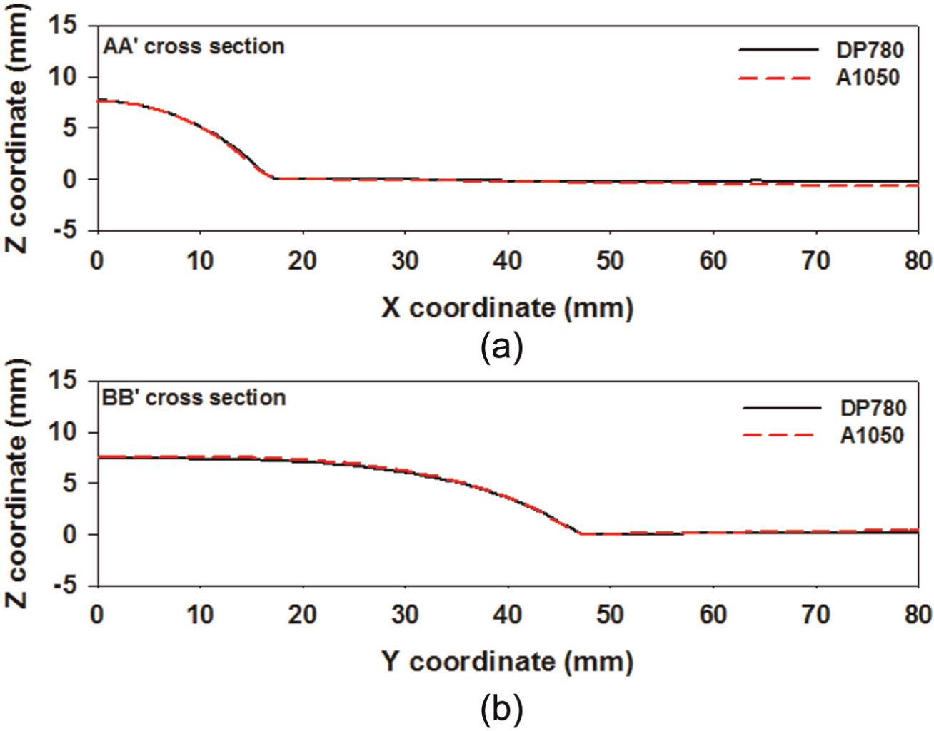
Comparison between cross-sectional shapes of DP780 steel sheet and aluminum driver plate at charge voltage of 5.1 kV: (a) AA′ and (b) BB′ cross sections.
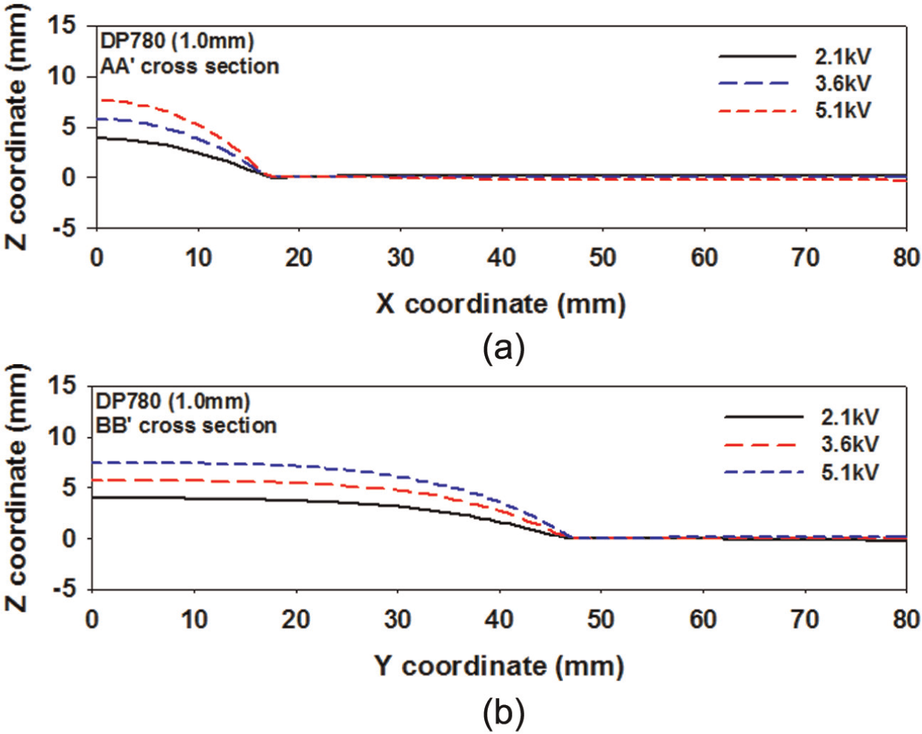
Cross-sectional shapes of DP780 steel sheet with aluminum driver plate after electromagnetic forming across different charge voltages: (a) AA′ and (b) BB′ cross sections.
Figure 9 shows the variation in the peak height with the charge voltage for the DP780 steel sheet without and with the A1050 driver plate. The peak heights are observed to linearly increase with the charge voltage. Oliveira et al. 20 studied the formability of aluminum alloy sheets using the electromagnetic forming process using a double flat spiral coil and found through free forming experiments that there is a near-linear relationship between the charge voltage and the forming height. The peak height in the steel workpiece sheet with the aluminum driver plate was four times more than that in the sheet without the plate. For example, at the charge voltage of 3.6 kV, the peak height was 1.4 and 5.62 mm without and with the driver plate, respectively. The forming efficiency was higher when the driver plate was used, as the plate allows for better forming with its higher conductivity and lower permeability. The magnetic pressure directly applied to the steel sheet workpiece was smaller than that to the aluminum driver plate. High conductivity also helps to easily induce the eddy current, and low permeability improves the ease of transmission of the magnetic field into the materials.
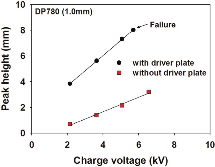
Variation in peak height with charge voltage for DP780 steel sheet without and with A1050 driver plates.
Figure 10 presents the variation in the peak height with respect to the charge voltage for three high-strength steel sheets with aluminum driver plates. The peak heights are observed to be the highest and lowest for the DP780 and CP1180 steel sheets with A1050 driver plates, respectively. This implies that the CP1180 steel sheet requires more energy than the DP780 steel sheet to form the same peak height. Considering the force equilibrium for cylindrical tubes, and assuming that the normal stress through the thickness reaches the tensile stress at equilibrium state (by neglecting the plastic work for the purpose of simplicity), the applied pressure p is given by
Variation in peak height with charge voltage for three high-strength steel sheet workpieces with A1050 driver plates.
where
Assuming that the deformed shape of the AA′ cross section is regarded as a part of the circle, the relationship between r and the height h is given by
where W is the width in the narrow direction (AA′ cross section) of the open-cavity die. In equation (14), r decreases until h becomes equal to W. The magnetic pressure on the three steel sheets with aluminum driver plates may be equal because the Lorentz forces between the plates and the coil are the same if the magnetic field transmitted into the steel sheets is neglected. The parameters r and h are related as multiples of the product of the tensile stress and sheet thickness
Figure 11 shows the deformation shapes for the three steel sheets with the driver plates at near failure. In all sheets, failure is observed to appear in the narrow corner of the open-cavity die. The locations of failure are the same for the steel sheets and the aluminum driver plates. Furthermore, failure is observed to occur at the same charge voltage in the aluminum driver plates and the steel sheets although the total elongation is lower for the former than the latter. The limit heights of the three sheets with aluminum driver plates are shown in Figure 12. Measurement of charge voltages at the exact moment of failure of the steel sheets during the electromagnetic forming experiments was difficult because the charge voltage was applied in a step-by-step fashion. The limit heights in Figure 12 occur between the heights right before and after failure. The largest and smallest limit heights were recorded for the DP780 and CP1180 sheets, respectively. We considered the forming limit strain under plane strain
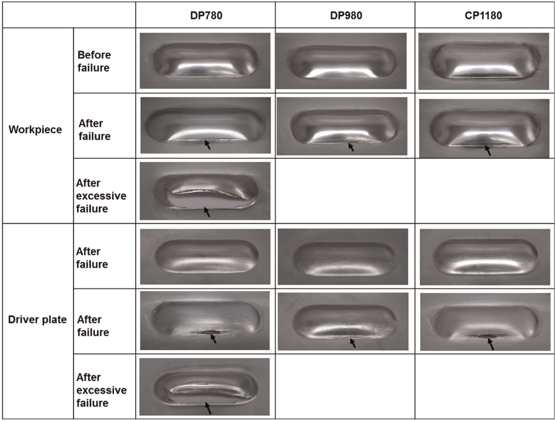
Failure trends for three high-strength steel sheet workpieces with A1050 driver plates (arrows represent failure location).
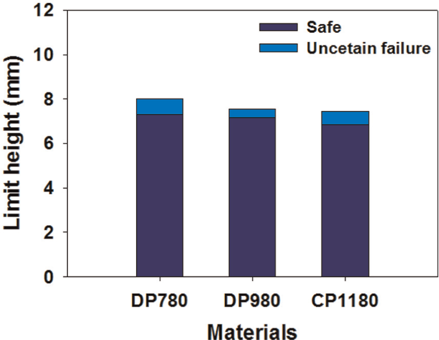
Limit heights for three high-strength steel sheet workpieces with A1050 driver plates.
According to equation (15),
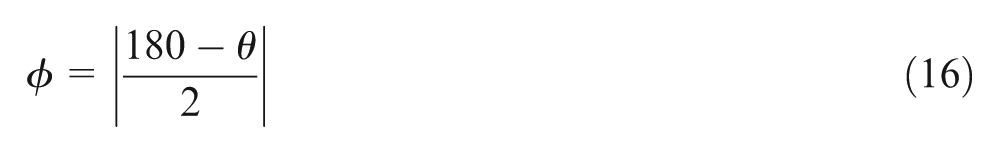
The amounts of springback for the three high-strength steel sheets with aluminum driver plates were measured after the electromagnetic forming. The angle
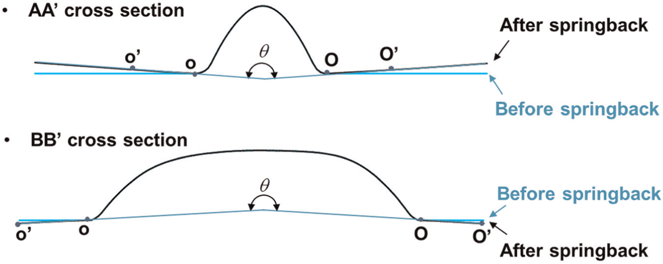
Schematic diagram for definition of springback angle.
The variations in the springback angle across charge voltage for the three high-strength steel sheets are shown in Figure 14. The springback angles in all experiments were found to be within 1°, which is too small for the charge voltage to have any discernible effect on the springback. The springback angle may appear to be smaller than the measuring error.
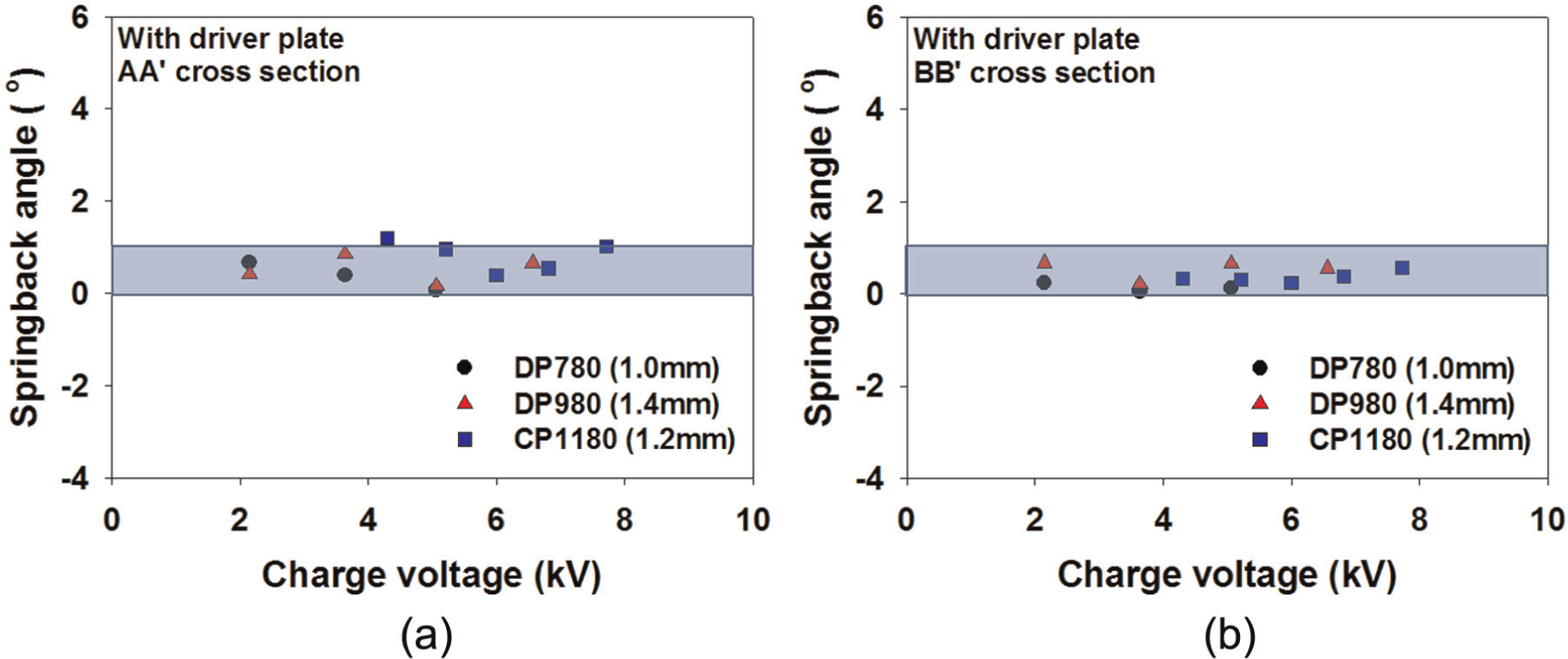
Variation in springback angle with charge voltage for three high-strength steel sheet workpieces with driver plates: (a) AA′ cross section and (b) BB′ cross section.
Generally, springback is not considered to be large during electromagnetic forming. 2 Our experiments validated this assumption for high-strength steel sheets, as shown in Figure 14. However, as is the case with past studies, our study too could not explain the cause of this behavior. Three possibilities can be considered: (a) the material could have been uniformly deformed because the male punch was not used, and the uniform strain distribution could have reduced the springback; (b) the temperature of the workpiece could have risen in a moment during electromagnetic forming because of Joule heating by the induced current, lowering the hardening curves and thereby reducing the springback; and (c) the pulsed current induced in the electromagnetic resonance circuit, which can be utilized to enhance the fatigue properties of the structural parts (as it may reduce the residual stress inside the material 22 ), could have worked similarly in the electromagnetic forming process to reduce residual stress, leading to reduced springback. In the future, we propose to investigate each of these possibilities in detail.
Conclusion
Three automotive high-strength steel sheets (DP780, DP980, and CP1180) were formed into hemi-elliptical protrusions under electromagnetic pressure. The change in forming behavior with respect to the charge voltage was investigated by examining the characteristics such as peak height, limit height, and springback angle. Aluminum driver plates were used for improving the forming efficiency, and their effect on the forming of steel sheets was also observed. Based on the experiments with electromagnetic forming of the high-strength steel sheets in this study, the following conclusions can be made:
The peak height increases with the increase in charge voltage in a near-linear relationship.
The use of aluminum driver plates accelerated the steel sheets. The peak heights in the steel sheets with aluminum driver plates were four times more than those in the sheets without aluminum driver plates.
The highest and lowest peak heights were recorded in the DP780 and CP1180 steel sheets with A1050 driver plates. The CP1180 steel sheet required more energy than the DP780 steel sheet to form the same peak height.
In all steel sheets, failure appeared in the narrow corner of the open-cavity die on which the plane strain deformation is dominant. The highest and lowest limit heights were recorded for the DP780 and the CP1180 steel sheets, respectively.
The springback angles in all experiments were within 1°, which is too small for the charge voltage to have any effect on the springback.
Footnotes
Declaration of conflicting interests
The authors declare that there is no conflict of interest.
Funding
This study was financially supported by the Fundamental Research Program of the Korea Institute of Materials Science (KIMS) and the R&D programs on Fusion Core Technology for Industry (No. 10040078) funded by the Ministry of Knowledge Economy (MKE), Republic of Korea.