
Abstract
The advanced high-strength steels have become an interesting alternative in automotive industry to reduce vehicle weight and therefore reduce fuel consumption. However, its wide application in the automotive industry is still limited due to challenges in formability, tool life and springback. The springback is pointed out in literature as the main problem that involves the mass production of structural components, and the aspects that show influence are still not fully understood. This work aims to statistically analyze the influence of process and tool parameters on the magnitude of the springback on five high-strength steels. In order to do so, the U-bending test was used and two process parameters and two tool parameters that are mentioned in the literature as the most influential were chosen. The results of the analysis of variance pointed out the influence of the blank holder force as the parameter of greatest influence on springback, followed by the tool radius and friction condition.
Introduction
The automotive industry undergoes a constant pressure related to environmental requirements, which mainly aim at reduction of emission of greenhouse gases into the atmosphere. Thus, car manufacturers came with an alternative technique to manufacture components with thinner steel sheets for mass reduction of the vehicle and consequently reduce fuel consumption and greenhouse gas emissions. However, to manufacture components with thinner sheets without compromising the safety aspects, manufacturers began to replace the conventional steels by high-strength steels (HSSs) and advanced high-strength steels (AHSSs).
With the use of conventional steels, the main concern is the elimination of necking and fracture during the process. Nevertheless, with the use of HSS, emphasis has been transferred to the dimensional accuracy and consistency of the products, and one of the problems encountered is the springback. This phenomenon causes a geometric distortion after forming which can be detrimental esthetically as well as damaging the assembly of components. The AHSSs are known for their multi-phase microstructure which provides many advantages during mechanical forming, but the forming behavior is unpredictable and is still not fully understood which creates challenges for efficient tool design.
In recent years, various experimental techniques have been developed to study and characterize the phenomenon of springback. Ling et al. 1 carried out L-bending tests in order to study by finite element analysis (FEA) how die parameters like gap—between the die and punch—die radius, step height and step distance affect springback. Zhang et al. 2 proposed a V-bending test that provides a high level of springback. The advantage of this test is that it provides easy measurements and, also, allows the study of the sensitivity of springback relative to the tool radius and sheet thickness (r/t), mechanical properties of the sheet and contact conditions. However, the drawback of these two tests is that they cannot propitiate the realistic forming conditions held in the industry. Kuwabara et al. 3 studied the springback using the stretch-bending test, but Raabe et al. 4 mention that this test does not allow a careful control of the stresses on the sheet during bending, and cannot exhibit bending followed by reverse bending, neither the big slide on the tool radius commonly observed in operations using dies. The test which is most widely used in the study of springback is the U-bend test—benchmark problem from the NUMISHEET’93 conference proposed by Makinouchi et al. 5 Furthermore, it allows very realistic representation of conditions of forming and the profile of the component. Chen et al. 6 used the U-bending test to analyze the influence of the tool radius in the sidewall curling region with different AHSS. The authors concluded that the angular change and the sidewall curling are more pronounced for smaller tool radii and thicknesses. Moreover, they observed that radius larger than 3 mm shows less influence on springback. Liu et al. 7 studied the blank holder force (BHF) variation in an attempt to reduce the springback phenomenon, because according to the authors, the correct BHF application is one of the most effective methods to solve the problem. Many researchers are continuously trying to use the Makinouchi test by means of computer simulation for the springback evaluation. Bekar et al. 8 investigated the reduction of the magnitude and the variation of springback of DP600 steels in U-channel forming within a robust optimization framework. They performed a simple sensitivity analysis, and the limit of elasticity was found to be the most important random variable. Kang and Cheon 9 conducted an analysis of residual stresses in the coupled processes of stamping and welding by finite element methods. Xu et al. 10 studied the influence of the integration points, the size of the mesh of the sheet and the punch velocity on the accuracy and efficiency of springback simulation.
Chen and Koç 11 reported a parametric computer analysis using FEA and design of experiments (DOE) in order to study the effects of BHF and friction on springback variation for an open-channel-shaped part made of dual-phase (DP) steel. The main conclusion was that the sidewall curl is very sensitive to the contact condition in the simulation, and in order to reduce springback variation, the standard deviations used for variable randomization have to be decreased virtually.
Lajarin and Marcondes 12 evaluated by numerical simulation the degradation of the elastic modulus during nonlinear unloading and how the choice of numerical parameters can affect the computational prediction of springback for AHSSs. However, the understanding of the influence of process and tool parameters on the occurrence of springback is still unclear and less investigated in literature.
In order to advance the subject a little further and as a contribution to the research gap still present in the state-of-art, this experimental study aimed to statistically analyze the influence of process and tool parameters on the magnitude of the springback. In addition to BHF and friction studied by Chen and Koç, 11 in this work, two additional tool parameters (tool radius and the gap between the die and punch) that are mentioned in the literature as the most influential on the springback were chosen. In the present study, five HSSs—HSLA490, DP600-A and DP600-B from two different suppliers, DP780 and DP980—were evaluated. In order to do so, the U-bending test was used combined with an analysis of variance (ANOVA) in order to identify which mean values were statistically different. All the data are discussed separately for each one of the five high-strength materials.
Materials and methods
Materials
The materials selected for this study were steel sheets used in the automotive industry (Table 1). The sheet of high-strength low alloy (HSLA) has been used for many years in the production of automotive body structures. It is a typical conventional HSS obtained primarily by micro additions of micro-alloying elements primarily to control grain size. The selected AHSSs were four DP steels with a range of ultimate tensile strengths (UTSs) of 600, 780 and 980 MPa from two different suppliers (A and B) and thicknesses of 1.5 and 2 mm.
Mechanical properties and thicknesses of the materials.
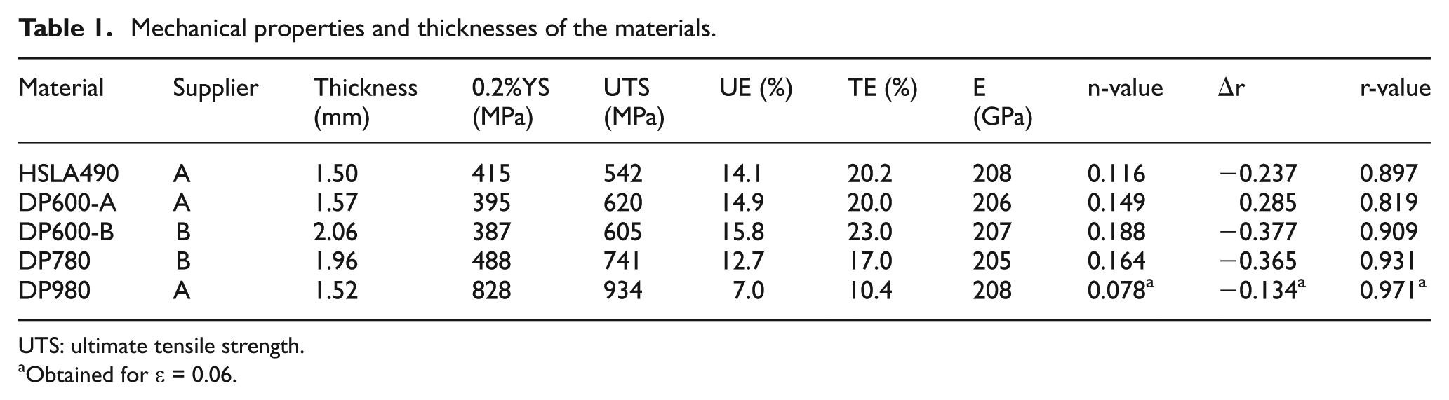
UTS: ultimate tensile strength.
Obtained for ε = 0.06.
DP600 and DP780 steels showed uniform elongation similar to HSLA490 steel, showing excellent combination of high-strength and good elongation—interesting properties for the automotive industry. The high-strength DP980 steel (UTS = 934 MPa) still showed a good elongation of 10.4%. All the steels analyzed showed some anisotropy.
Figure 1 shows the engineering stress–strain curves. DP steel exhibits higher initial work hardening rate, higher UTS and lower yield strength/tensile strength (YS/TS) ratio than HSLA490. DP600—from suppliers A and B—showed different behavior between them. DP600—from supplier B—showed a small yield point elongation, while DP600—from supplier A—showed a large initial hardening.
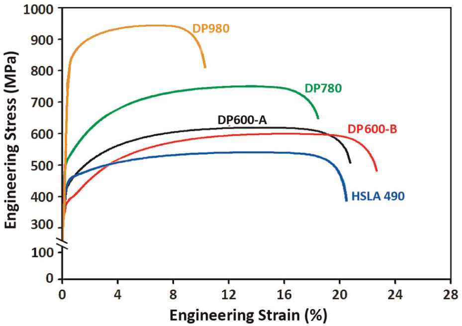
Engineering stress–strain curves of the five tested materials.
U-bending test
The simple U-bend test—benchmark problem from the NUMISHEET’93 conference—was employed to investigate the influence of process and tool parameters on springback (Figure 2(a)). The tool forms the sheet in a channel profile that is quite common in vehicle structural components and is very suitable to springback.
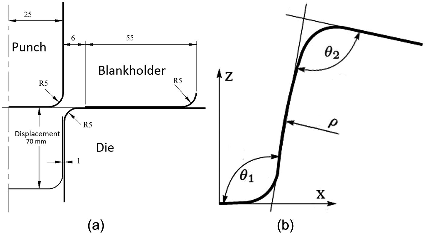
Benchmark NUMISHEET’93 (Makinouchi et al., 1993): (a) U-bend tooling (mm) and (b) springback measurements.
In order to study the influence of the process and tool parameters on the springback, a factorial design of 24 for each material was proposed. Table 2 shows the four parameters selected with two levels each.
Levels for the process and tool parameters.
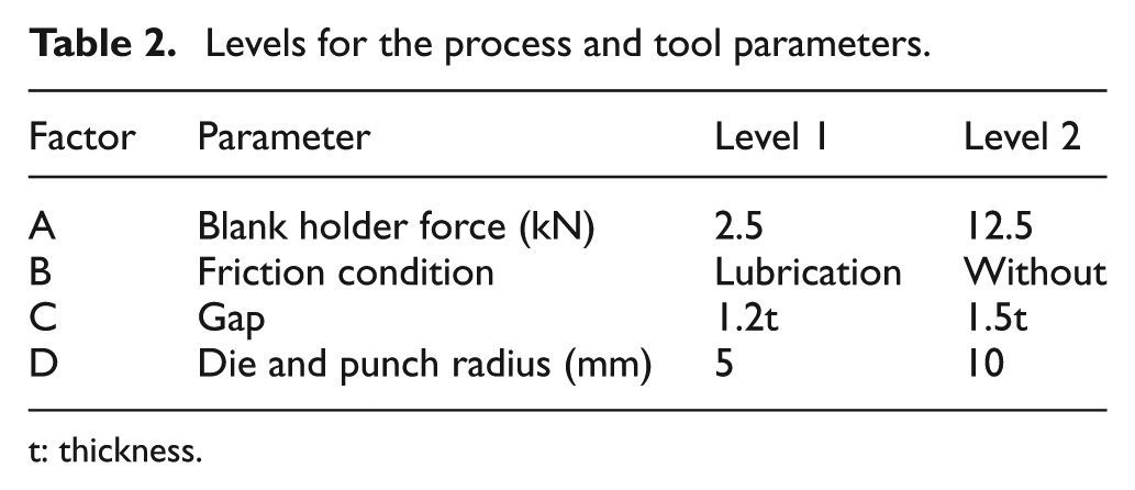
t: thickness.
The tool radius and gap—between the die and punch—are found in the literature as the two tool parameters that show influence on springback, as well as BHF and the lubrication are found as the process parameters that also show influence.11,13–15
For level 1, a BHF of 2.5 kN is the default value proposed by Makinouchi et al. 5 After preliminary tests, the BHF value of 12.5 kN was set for level 2—maximum BHF before the rupture of the material. The friction condition was tested with and without lubrication, and the used lubricant was hydraulic automotive oil. The used gap was based from the work of Sadagopan and Urban, 14 and the radius of the tool (die and punch) of 5 mm is the default value of the U-bend benchmark tool. However, the sheet thickness used for the tests with this tool is typically 0.78 mm which results in a relative radius/thickness ratio of 6.5 mm (r/t). In order to maintain close relationship with the sheets of 1.5 and 2 mm used in this work, a radius of 10 mm was also defined (r/t of 6.6 mm for sheets of 1.5 mm). Table 3 shows the 16 arrangements of the parameters that were used—as proposed by the 24 factorial design.
Experimental conditions for U-bending test.
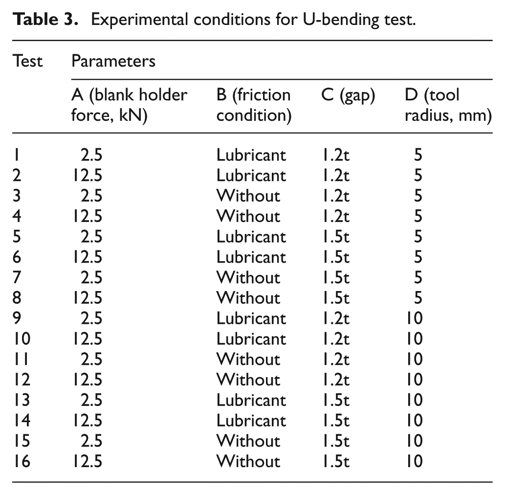
Other parameters and test conditions were kept constant, such as speed of the punch (10 mm/s), displacement of the punch (70 mm) and test specimen dimensions (35 mm × 300 mm). The samples were taken in the rolling direction.
Measurement procedure and techniques of analysis
The profile of the formed specimens was scanned with a resolution of 600 dpi (dots per inch) after the U-bending operation. The scanned images were analyzed in a computer-aided design (CAD) software, and three springback measurements were carried out following the procedure reported in Makinouchi et al. 5 : (a) angular change in the wall angle (θ1), (b) flange angle variation (θ2) and (c) sidewall curl radius (ρ) (Figure 2(b)).
The θ1, θ2 and ρ were statistically analyzed using the ANOVA to identify which variable presented statistical significance in the results. The analysis of mean values significance was made about the factor ρ. In these cases, the larger the factor ρ, the closer the experiment reaches the null hypothesis. Therefore, a factor ρ about 5% was adopted to help identifying mean value with statically significant differences among the factors. 16
Experimental results
The influence of process and tool parameters on the occurrence of springback was statistically analyzed for each material. Subsequently, the overall results are discussed.
HSLA490 steel
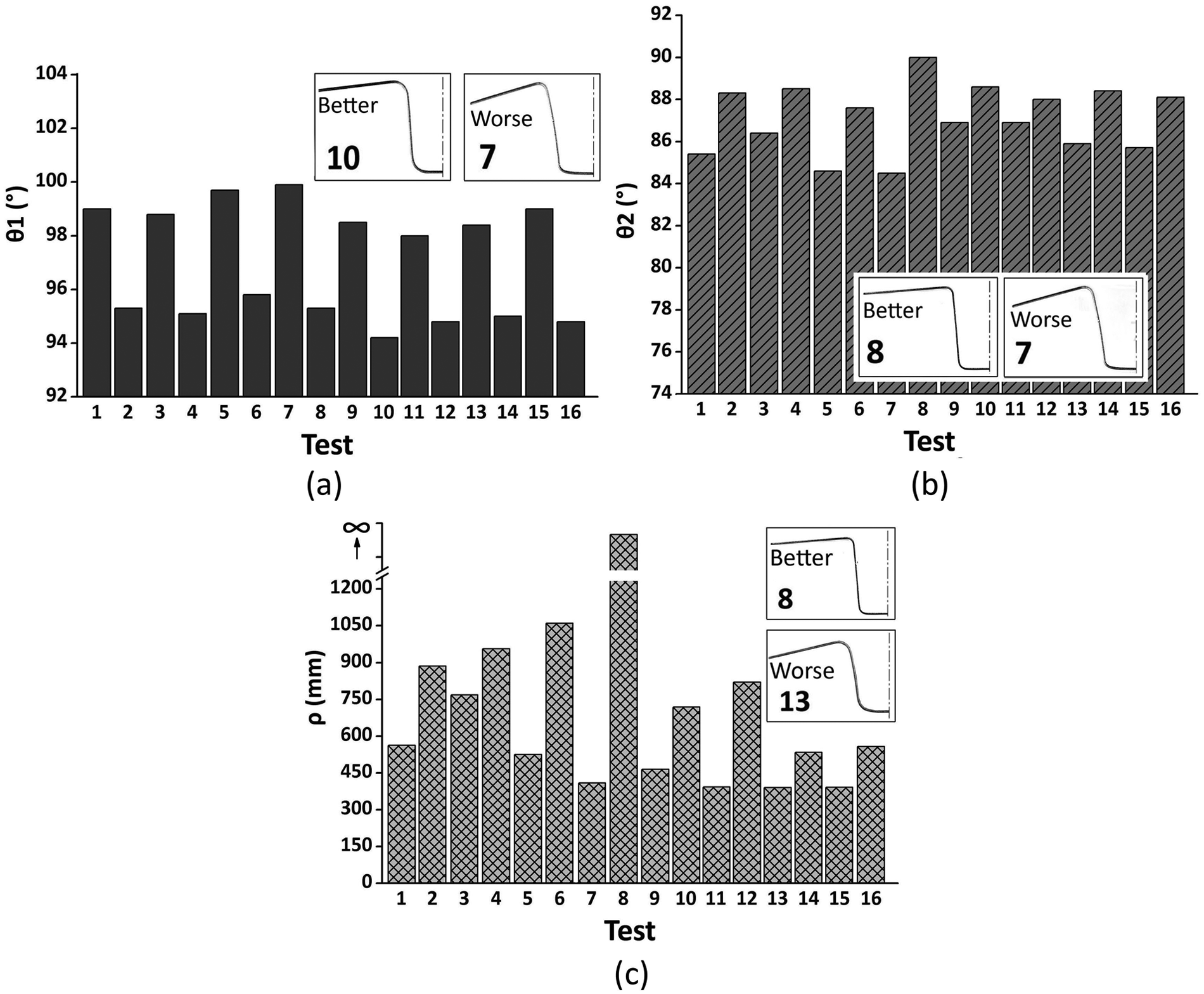
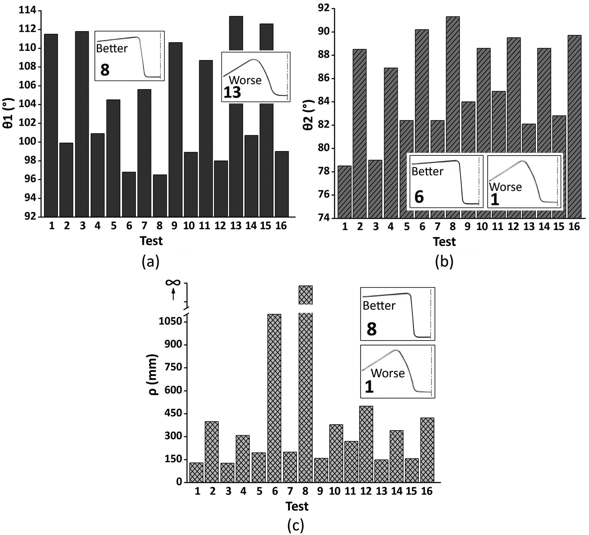
Figure 3 shows the springback measurements plotted as θ1, θ2 and ρ. For all results the values for θ1 and θ2 closed 90° and larger ρ are better results (indicates lower springback). A great difference between the best and worst results was observed for all three analyzed cases, that is, 9.2° for θ1, 10° for θ2 and above 1000 mm for ρ. This indicates that the combination of parameters for each test condition shows great influence on the springback. However, in order to evaluate the real influence of each parameter on the present work, ANOVA analysis were carried out.
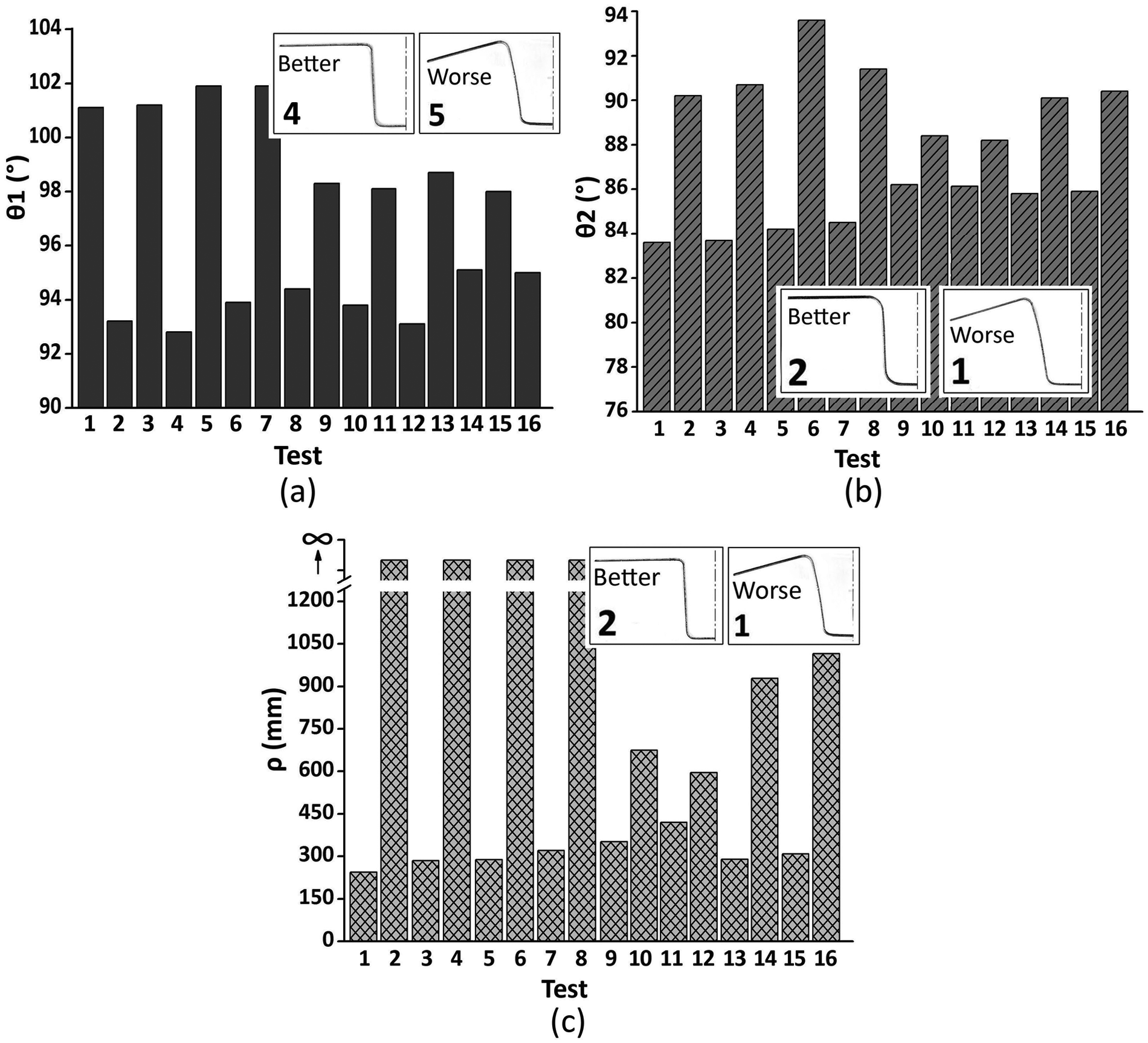
HSLA490 springback after the U-bending test: (a) θ1, (b) θ2 and (c) ρ.
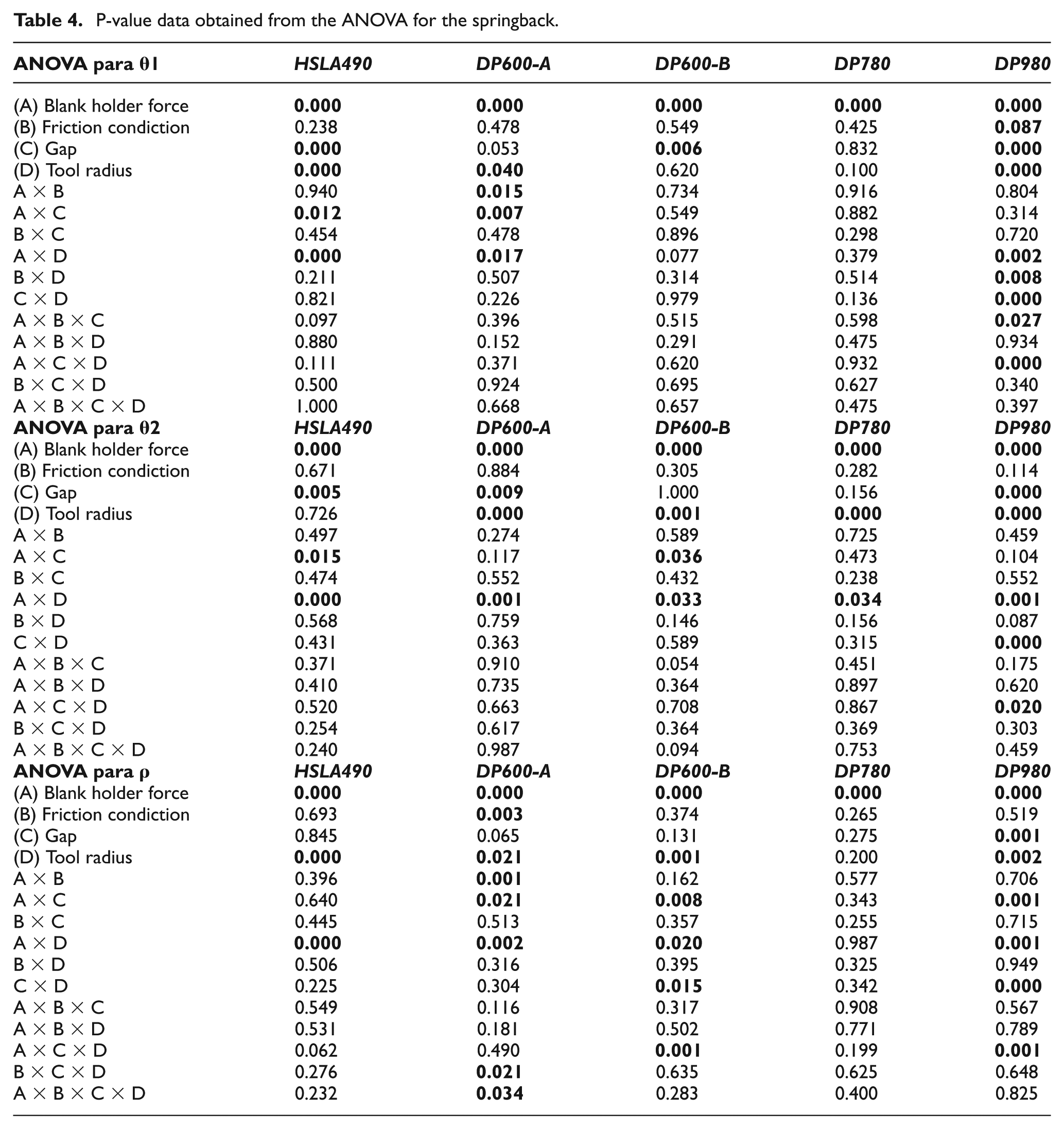
According to ANOVA, the BHF, gap and tool radius were parameters that had significant influence on the springback (Table 4). It should be noted that, for a correct interpretation of statistical results cannot be considered the main effect of a factor when it is involved in an interaction also significant. For this reason, all significant interactions on the springback—θ1, θ2 and ρ—were cross-analyzed. However, because of the large amount of generated data, only the most significant data are illustrated in Table 4.
P-value data obtained from the ANOVA for the springback.
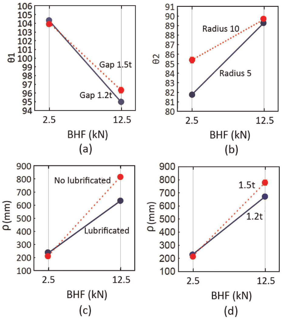
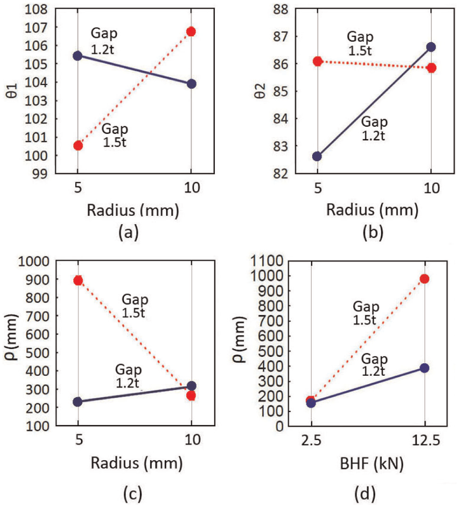
The more significant interaction was AD when θ1, θ2 and ρ were analyzed (Figure 4). In the three measured springback—θ1, θ2 and ρ—the change in BHF of 2.5–12.5 kN greatly influenced the results, particularly when tool radius of 5 mm (r/t = 3.3) was used. In θ1 and θ2, the interaction AC was also observed as significant; however, in this case, the significance was influenced by the BHF and not by the gap. The factor that most influenced effectively the best results in three cases of springback with steel HSLA490 was the BHF of 12.5 kN (see Table 4).
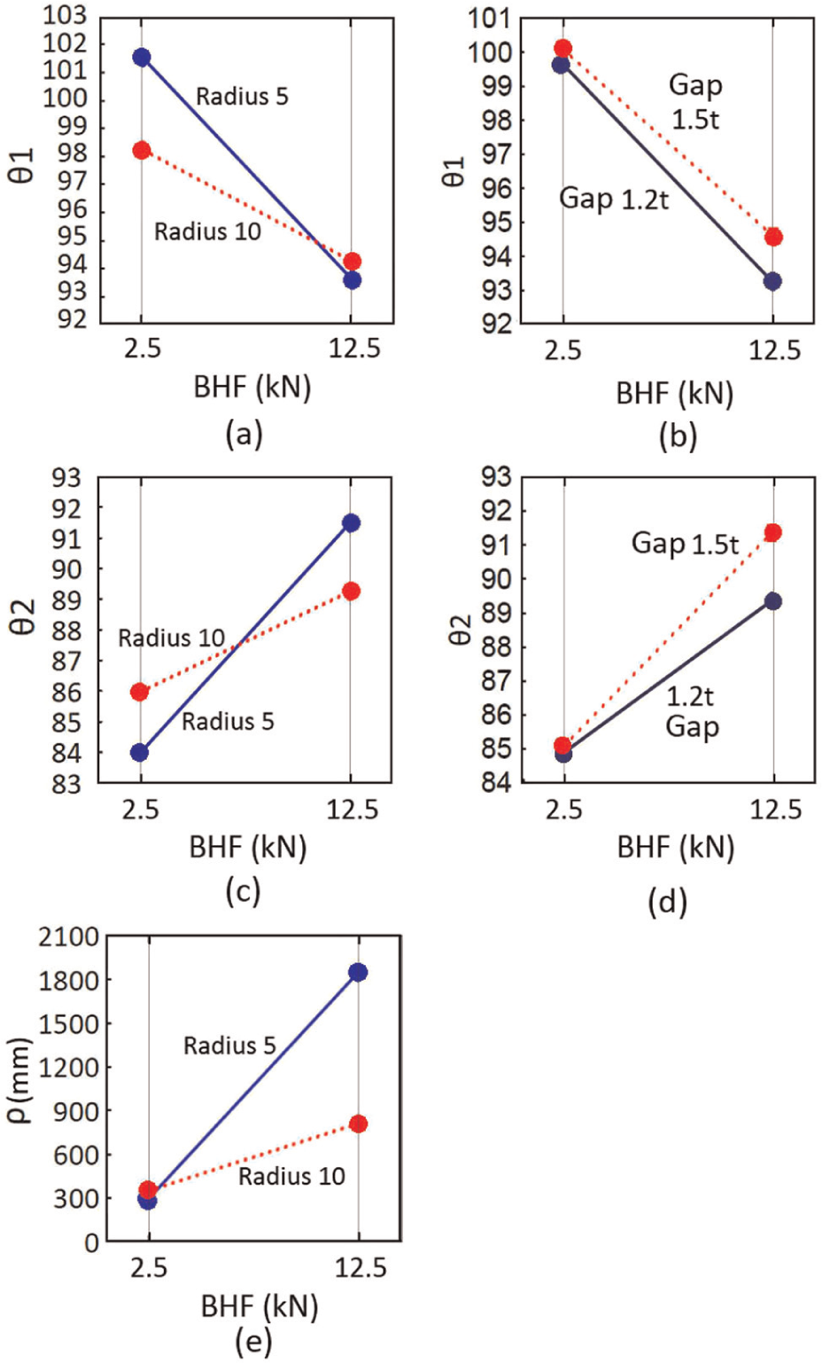
Most significant interactions for HSLA490 steel: (a) AD for θ1, (b) AC for θ1, (c) AD for θ2, (d) AC for θ2 and (e) AD for ρ.
DP600-A steel
Figure 5 shows the springback after U-bending tests with DP600-A steel. The difference between the better and the worst springback was 11.3° for θ1, 9.7° for θ2 and 762 mm for ρ.

Springback after U-bending test with DP600-A steel: (a) θ1, (b) θ2 and (c) ρ.
As can be seen, AC for θ1, AD for θ2 and AB for ρ were the more significant interactions observed (Figure 6). For θ1, the change in BHF showed major influence for both conditions of gap—changing the springback in almost 9°. But as a general result, the influence of the gap was very small. For θ2, the change in BHF, with a radius of 5 mm, showed a variation of springback up to 8° and 4.5° when radius of 10 mm was utilized. When BHF of 12.5 kN was used, significant influence of the chosen radius was observed. When ρ was analyzed, it was observed that the changes in BHF showed influence on springback for both lubricating conditions studied, being somewhat greater in the condition without lubrication. Furthermore, another significant interaction was AC when ρ was analyzed. Figure 6(d) illustrates that the significance was influenced by the BHF and not by the gap. In summary, the parameter influencing springback for the best results for θ1, θ2 and ρ was the BHF of 12.5 kN.
Most significant interactions for DP600-A steel: (a) AC for θ1, (b) DA for θ2, (c) AB for ρ and (d) AC for ρ.
DP600-B steel
Figure 7 shows the springback after U-bending tests for DP600-B steel. The difference between the lowest and highest result was 5.7° for θ1, 5.5° for θ2 and above 1000 mm for ρ. DP600-B was the material that showed the lowest springback.
Springback after U-bending test with DP600-B steel: (a) θ1, (b) θ2 and (c) ρ.
For DP600-B steel, no significant interaction for θ1 was observed. For θ2, the more significant interaction was AD, and AC was the most significant interaction for ρ (Figure 8). For θ2, with a radius of 5 mm, the BHF change showed variation on springback of almost 4°. On the other hand, with a radius of 10 mm, the springback variation was slightly more than 2°. That is, when the largest BHF was used—12.5 kN—the tool radius does not show significant influence on θ2. AC was another significant interaction for θ2. However, as in previous cases, the influence was promoted by BHF and not by the gap. When analyzing ρ, BHF changes showed significant influence when the gap of 1.5t was used. When the gap was changed, it had a larger influence only for higher BHF forces.
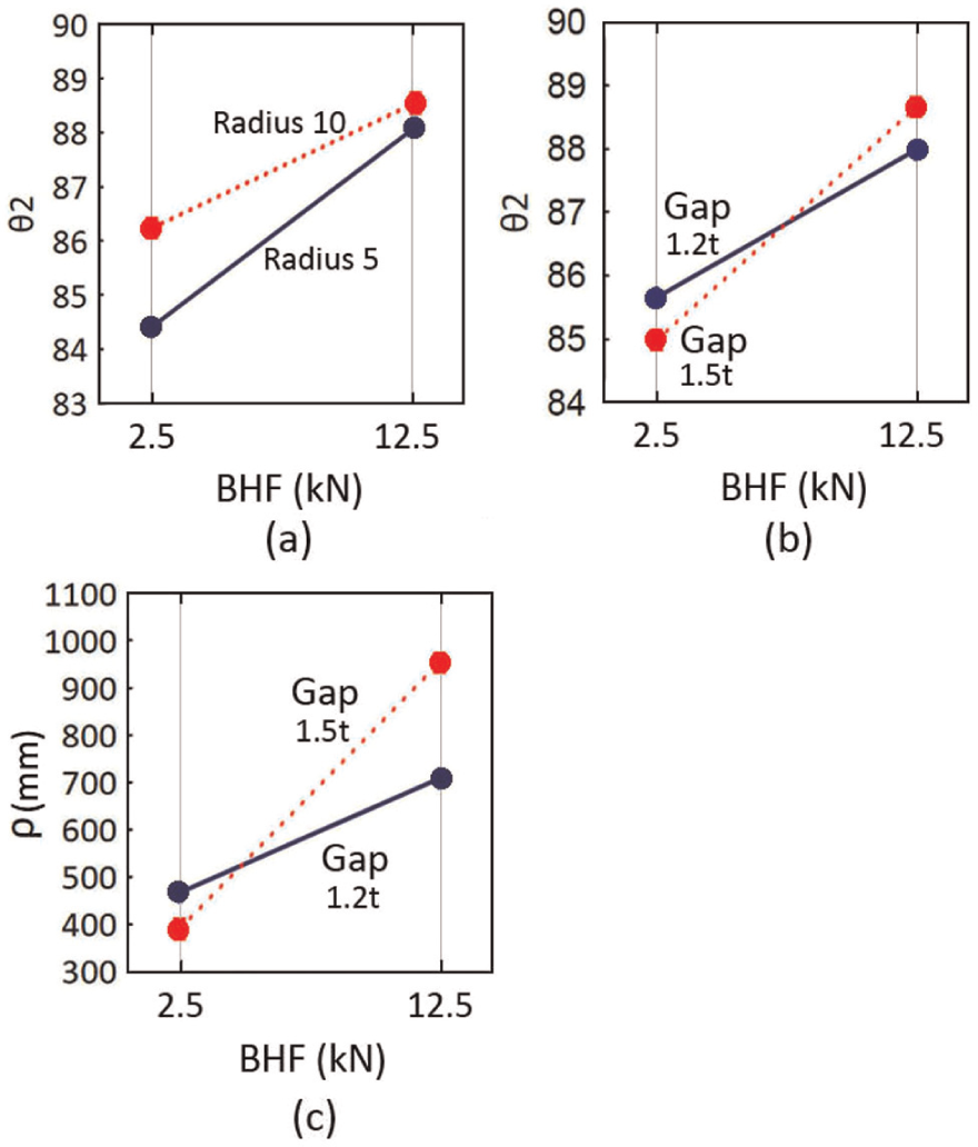
Most significant interactions for DP600-B steel: (a) AD for θ2, (b) AC for θ2 and (c) AC for ρ.
In both cases, the factor that most influenced the lowest springback was the BHF of 12.5 kN. When ρ was analyzed in association with the gap of 1.5t, the BHF showed even more influence.
DP780 steel
Figure 9 illustrates the springback after U-bending tests for DP780 steel. The springback did not show large variation among the 16 trials, that is, it was not very sensitive to the tested variables. The difference between the lowest and highest springback was 8.3° for θ1, 5.8° for θ2 and only 180 mm for ρ.
Springback after U-bending test for DP780 steel: (a) θ1, (b) θ2 and (c) ρ.
The only significant interaction in the results was AD for θ2 (Figure 10). When the radius of 5 mm was utilized, the BHF variation showed springback variation of more than 3°. For the radius of 10 mm, the springback variation was less than 2°. Moreover, the changes in radius had little effect when combined with BHF. In this case, the combinations of factors that showed influence for lower springback (θ2) were the combination of BHF of 12.5 kN and radius of 10 mm (r/t = 5 mm).
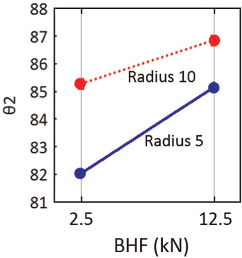
Most significant interactions for θ2 for DP450/DP780 steel.
DP980 steel
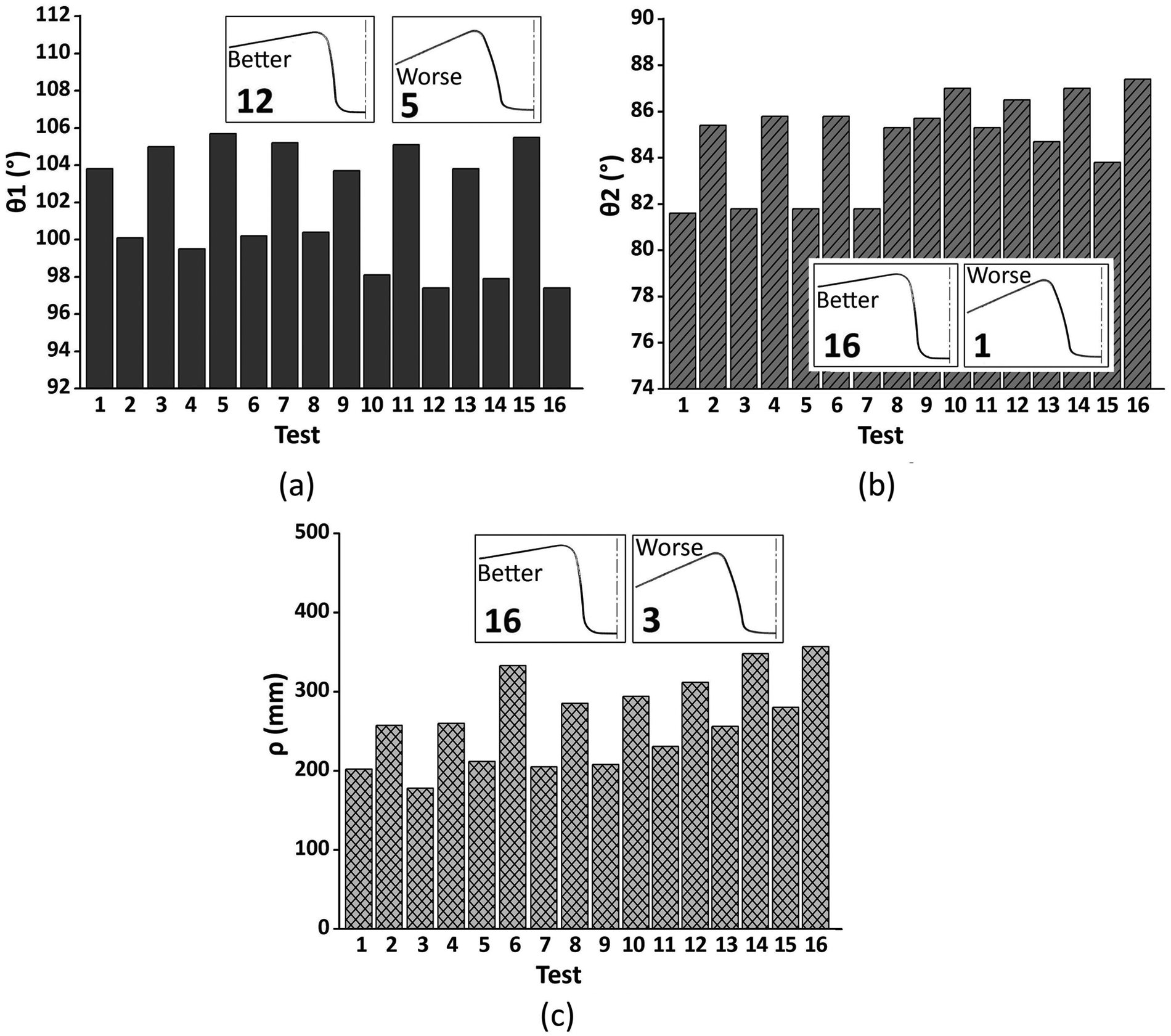
Figure 11 shows the springback after U-bending tests for DP980 steel. The springback shows large variation among the 16 tests carried out. The difference between the lowest and highest springback was 17° for θ1, 13° for θ2 and above 1000 mm for ρ. This shows that DP980 steel is very sensitive to the choice of the studied parameters.
Springback after U-bending test with DP980 steel: (a) θ1, (b) θ2 and (c) ρ.
According to ANOVA, the most significant interaction for θ1, θ2 and ρ was CD (Figure 12). In all three cases, the change of the gap of 1.2t–1.5t using 5 mm radius (r/t = 3.3 mm) caused significant change in the results, whereas the combination of gap of 1.2t and radius of 5 mm strongly influenced the worst results. Moreover, when the radius of 10 mm (r/t = 6.6 mm) was used, the observed variation in the results was very small.
Most significant interactions for DP980 steel: (a) CD for θ1, (b) CD for θ2, (c) CD for ρ and (d) AC for ρ.
For θ1, the combination of parameters that showed influence for the best results was the gap of 1.5t and radius of 5 mm. For θ2, the parameter that influenced the best results was the gap of 1.5t.
As observed for θ2, when ρ was analyzed, the variations in the gap showed significant influence only when the radius of 5 mm was used. The change in radius showed significant influence only for the gap of 1.5t. AC was another significant interaction, however, strongly affected by the gap. Thus, the combinations of factors that showed influence for the best results for ρ were the combination of gap of 1.5t, radius of 5 mm and BHF of 12.5 kN.
Discussion
In the previous section, the springback measurements of each material were presented separately and the influence of the parameters analyzed was briefly discussed. Among the five tested materials, the parameter that showed the largest influence on springback (θ1, θ2 and ρ) was the BHF. The change of BHF from 2.5 to 12.5 kN showed significant influence for all the results, and the BHF of 12.5 kN influenced the best results, that is, the lowest springback. During the deep drawing process, the sheet slips and plastically deforms on the tool radius. As a result of this plastic deformation, there are compressive stresses acting in the region of the sheet in contact with the radius of the die and, consequently, tensile stresses in the opposite region. When the large BHF was used, it strongly restricted the slip of the sheet on the radius of the die, directing the stresses in the wall of the test specimen in the longitudinal direction—inducing stretching of the sheet. Thus, the elastic recovery on the tool radius was lower and the sidewall curling too.
Another factor that showed significant effect on almost every result was the radius of the die. Moreover, when the radius was combined with other factors such as BHF or gap, it also had a significant effect on springback.
The gap between the die and punch appeared in almost half of cases as a significant main effect and in more than half as a significant association. However, as can be seen by analyzing with ANOVA, the main effect showed small significance. Furthermore, as can be seen by the graphs of interactions with the gap, the significances were influenced by other factors and not by the gap. It is worth noting the exception with DP980 steel, where the most significant interaction for θ1, θ2 and ρ was between the gap and the radius—with large influence of the gap. In this case, in general, the larger gap showed larger influence for the best results.
The lubrication condition appeared only once as significant main effect and three times as an association with some significance. For DP600-A steel, the condition without lubrication showed influence for the best results of ρ—roughness of 1.34 µm (the highest among the steels tested). The condition without lubrication associated with higher roughness produced the effect similar to the largest BHF, that is, restriction of the slip of the sheet on the radius of the die.
In summary, the largest BHF, the radius of 5 mm and the contact without lubrication are the conditions that reduced the slip of the sheet on the radius of the die inducing stretching and that influences the lower springback.
Probably, the largest influence of the combination of the parameters in springback with HSLA490, DP980 DP600-A steels is due to the thinner sheet thicknesses (1.5 mm) compared to DP600-B and DP780 steels that were 2 mm thick. Steels with a thickness of 2 mm had marked influence only of the BHF parameter.
Conclusion
Five high-strength materials were analyzed that are replacing the conventional steels in the vehicle body structure. The analysis was presented by means of a statistical analysis of each parameter that can show important influence on springback. These HSSs are known for their multi-phase microstructure which provides many advantages during mechanical forming, but the forming behavior is unpredictable and is still not fully understood which creates challenges for efficient tool design. The main contribution of this work was to analyze the main process and tool parameters that can affect the springback. The most interesting feature observed in this study was that the restriction of the slipping of the sheet on the radius of the die induces stretching of the sheet that can promote the reduction of the springback. Among the process parameters and tool parameters tested, the largest BHF, the smallest radius and the surface contact without lubrication influenced the best results. Among these parameters, the BHF of 12.5 kN (largest force) was the parameter that most influenced the best results (lower springback).
Footnotes
Acknowledgements
The authors thank ArcelorMittal and Usinas Siderúrgicas de Minas Gerais S.A. (USIMINAS) for providing steel samples.
Declaration of conflicting interests
The authors declare that there is no conflict of interest.
Funding
This study was funded by the scholarship from CNPQ Agency (Brazil).