
Abstract
Friction plays an important role in the corner filling behavior during hydro-forming of rectangular section. In order to study the variation in corner filling behavior with internal pressure under the condition of different coefficients of friction, Gurson–Tvergaard–Needleman ductile damage model was used to describe material deformation involving damage evolution. First, an experimental–numerical hybrid method was applied to determine the parameters of critical porosity and failure porosity in Gurson–Tvergaard–Needleman ductile damage model. Second, a model describing the deformation behavior was established, in which the deformation zone was divided into three parts: sticking zone, sliding zone and corner zone. Third, the effect of coefficient of friction on the corner filling process was studied through simulation and experiments. The results show that as the internal pressure increases, the sticking zone starts at certain pressure and increases rapidly until taking over the whole contact length. Sticking friction will lead to greater thinning, and bursting occurs rapidly at the transition zone. Furthermore, the increase in the coefficient of friction will lead to greater variation in thinning and corner radius. For µ = 0.05 in experiments, corner filling is acceptable without bursting, correspondingly the final internal pressure is 67 MPa.
Keywords
Introduction
Due to the increasing demands for lightweight parts in automotive, aircraft and aerospace industry, hydro-formed parts of aluminum alloy with various rectangular or similar geometries have been widely used to reduce weight and improve stiffness.1–6 The internal pressure during corner filling process is inversely proportional to its radius value. If a very small corner radius in the rectangular section parts is needed, a very high pressure is necessary to obtain the designed shape.7,8 Hence, a method of improving coefficient of friction to reduce internal pressure and control thinning is usually used.
Hwang and Chen 9 established a mathematical model that considered sliding friction between tube and dies and explored the plastic deformation behavior of the tubes during hydro-forming process in square cross-sectional dies. The effect of the coefficient of friction on final forming pressure and thickness distribution was particularly discussed. Orban and Hu 10 developed an analytical model in which the deformation zone was divided into straight wall and corner zone. When the sticking friction started at straight wall, the material in this zone did not further deform. Yuan et al. 11 studied the effects of strain-hardening exponent, die corner radius and initial tube wall thickness on the thickness variation at the corner. Based on the deformation behavior, automotive parts such as rear axle arm, turning arm and engine cradle were well formed. Kridli et al. 12 used the software ABAQUS to examine the thickness variation and the corner radius in square cross-sectional hydro-forming. In simulation, a two-dimensional plane strain finite element model was used, but the forming limit and fracture were not predicted.
In order to predict fracture in ABAQUS software, Gurson–Tvergaard–Needleman (GTN) ductile damage model as one of the well-known models for ductile damage has been extensively used for different materials and processes.13–15 Abbasi et al. 16 predicted the forming limit diagram (FLD) of tailor-welded blank using ABAQUS software, in which the GTN model was applied as a failure criterion. He et al. 17 predicted the forming limit stress diagram (FLSD) of AA5052 aluminum alloy by GTN model which was adopted to identify the necking initiation area and determine the maximum principal stress close to crack. Varma et al. 18 analyzed the localized necking of aluminum alloy tubes during hydro-forming using an anisotropic version of the Gurson model. Butcher et al. 19 also used a variant of GTN model to study the fracture behavior of hydro-forming of DP600 tube. In simulation, the formability and fracture location were in good agreement with the experiments.
In this article, the effect of the coefficient of friction on the corner filling behavior of AA5052 aluminum alloy in hydro-forming was investigated based on the GTN ductile damage model. Simulation results confirmed by related experiments indicated that GTN ductile damage model could provide a reliable prediction of fracture.
GTN ductile damage model
Theory basis
In this study, the GTN ductile damage model is used to predict fracture. The yield function of GTN ductile damage material model is a pressure-sensitive yield function and can be expressed as follows 14
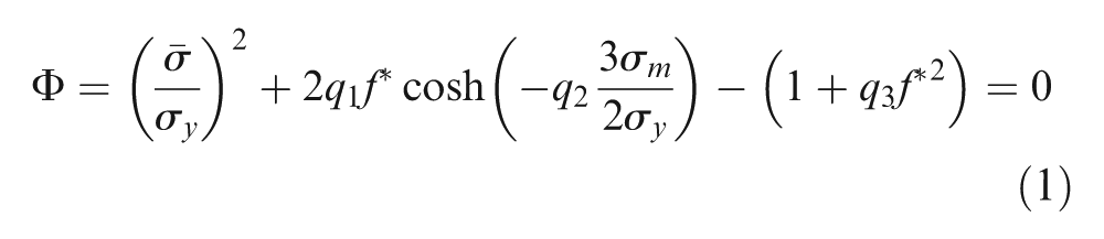
where
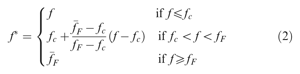
where
The growth rate of total void volume fraction
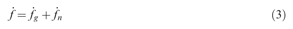
where
For the initial state of materials,
The growth rate of existing voids
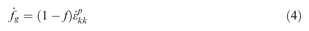
where
The nucleation rate of new voids can be expressed by a plastic strain-controlled nucleation rule as follows
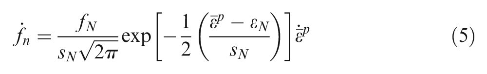
where
Selection and identification of GTN model parameters
In order to apply GTN ductile damage model in the finite element analysis, parameters of AA5052-O aluminum alloy mentioned below would be needed:
The elasticity parameters: Young’s modulus
The plastic behavior was described by Swift-type hardening law
The values of the constitutive parameters in GTN ductile damage model were determined by Tvergaard and Needleman:
14
The nucleation parameters
Coalescence parameters
As shown in Figures 1 and 2, the original voids and fraction porosity of AA5052-O aluminum alloy were observed by scanning electron microscope (SEM). For each testing condition, eight SEM micrographs were analyzed, thus ensuring that 1000 particles were sampled totally. The area volume fraction was counted by Image-Pro plus software 5.0 in a view field, and the value was defined by the area ratio of void area to view field area. Hence, the initial void volume fraction
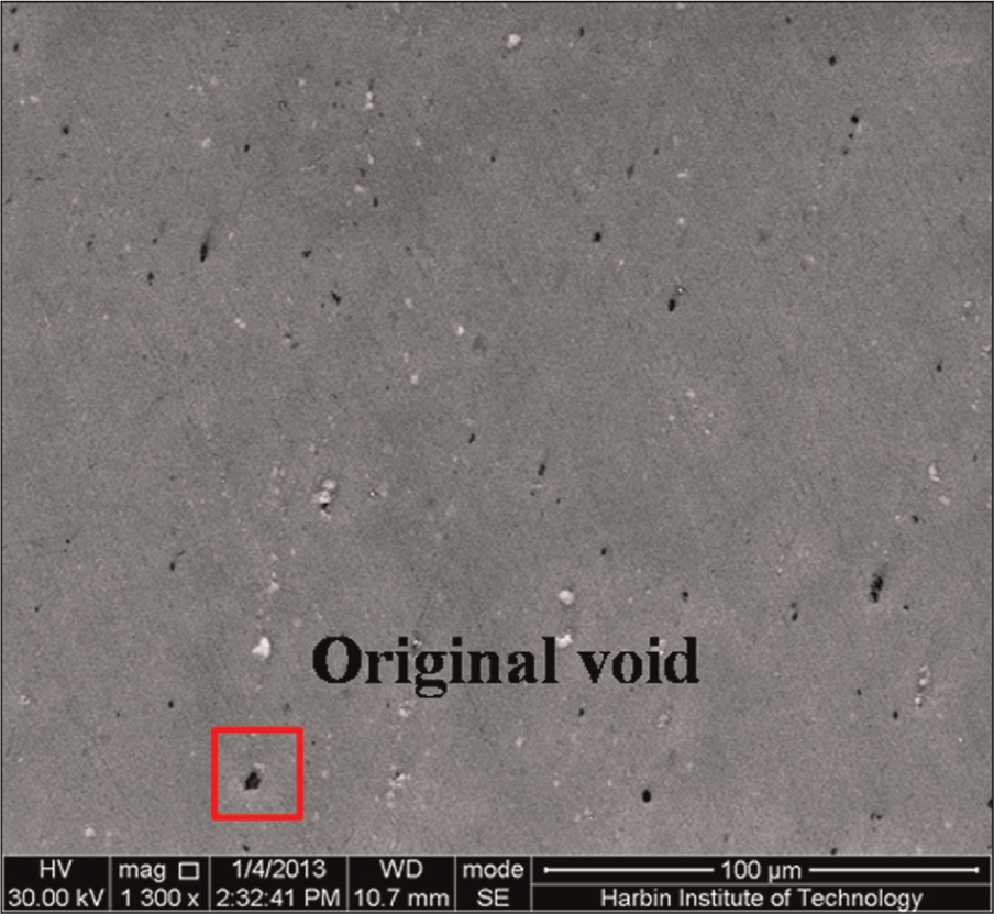
SEM image showing original voids before plastic deformation.
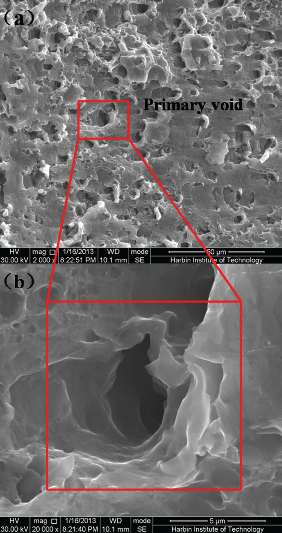
SEM images showing coalescence voids after fracture: (a) 2000× and (b) 20,000×.
The critical porosity
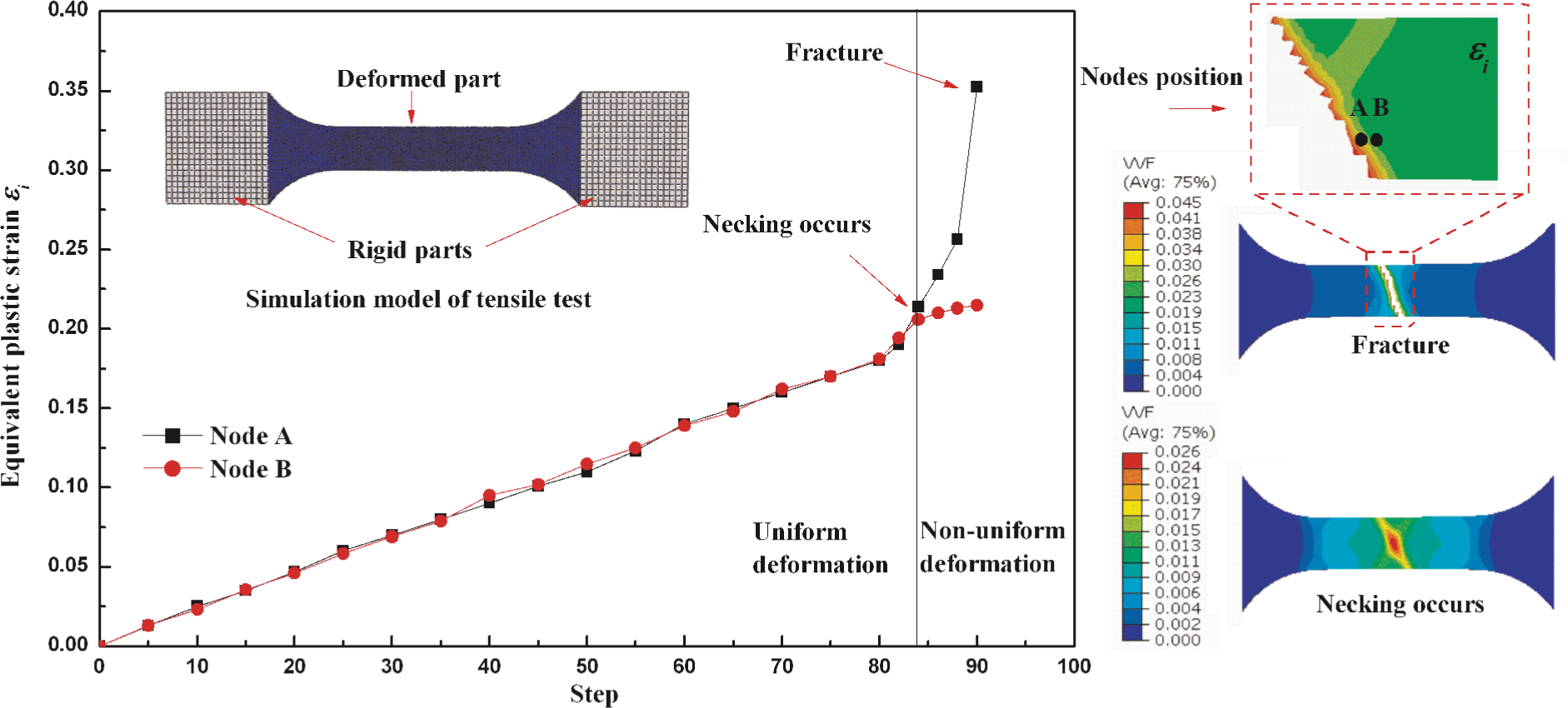
The equivalent plastic strain distribution of localized neck node A and its vicinity node B from a deformed specimen was obtained from the first simulation as shown in Figure 3. During most of the deformation process, the values of equivalent plastic strain at the two points are similar. Once the equivalent plastic strain value at node A increases rapidly than node B, localized necking is assumed to occur. It means that the strain carrying capacity loss appears, and the critical porosity
Determination of critical porosity
An experimental–numerical hybrid method was applied to verify whether these parameters obtained both in references and experiments were suitable to the materials in this article. In previous researches23,24 conducted, the damage constants were calibrated using the load–displacement curve for a selected uniaxial tensile test both in simulation and experiments, which was used to capture the failure strain. In experiments, the specimens are obtained from the tube along the axis direction, and the gripping heads are flatted before tensile test. The comparison of the load–displacement curves of tensile specimen between experiments and simulation is shown in Figure 4. At the early stage of deformation, simulation curve does not match the experiments very well, owing to the true stress–strain curve used in simulation, and no yield point elongation exists. However, the simulation curve shows a good agreement with experiments during hardening; especially at the same displacement, the maximum loads are obtained both in the simulation and experiments. Totally, the GTN damage parameters used in this study are effective.
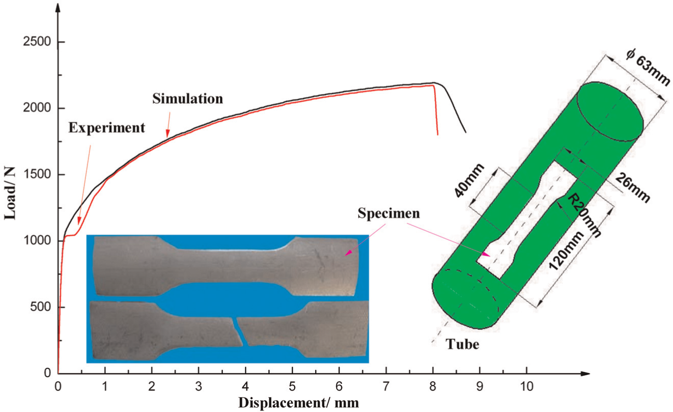
Comparison of displacement–load curves of tensile specimens between experiments and simulation.
Research methods
Experimental setup
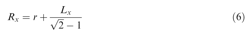
Figure 5(a) shows the 3150 kN hydro-forming machine. Figure 5(b) shows the experimental setup, which contains upper die, lower die, left punch, right punch and displacement sensor. Figure 5(c) shows the geometric schematic between displacement and corner radius. The variation in the corner radius as the internal pressure increases can be calculated and expressed as equation (6). The measurement precision of displacement sensor is 0.02 mm, and accordingly, the measurement precision of corner radius is 0.05 mm.
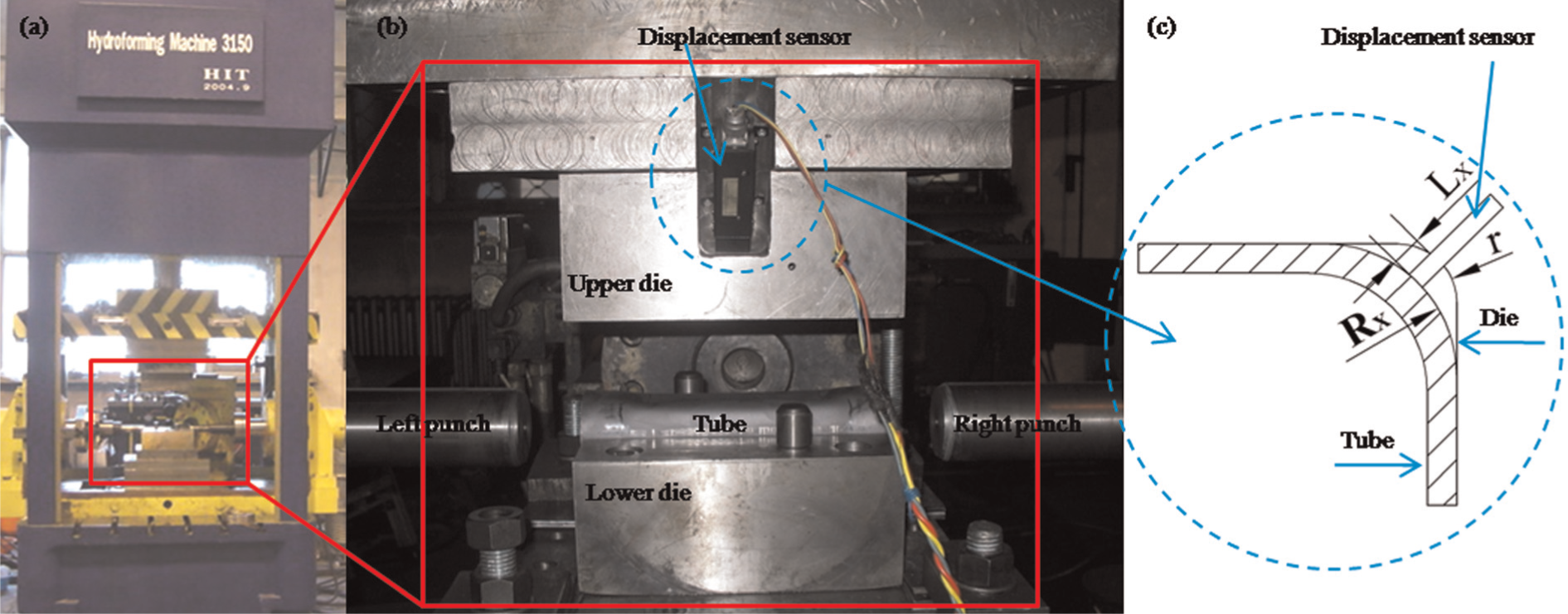
Experimental setup: (a) machine, (b) tube and dies and (c) geometric schematic of displacement sensor.
Figure 6 shows the dimension of designed section by tube hydro-forming, with an expansion rate of 10.8%. The initial thickness and outer diameter of the tube are 1 and 63 mm, respectively. During the experimental process of hydro-forming, the selection of coefficient of friction depends on the use of variable lubrication. According to the methods mentioned in previous articles,25–27 coefficient of friction during hydro-forming has been measured, and it almost keeps constant when internal pressure is less than 100 MPa
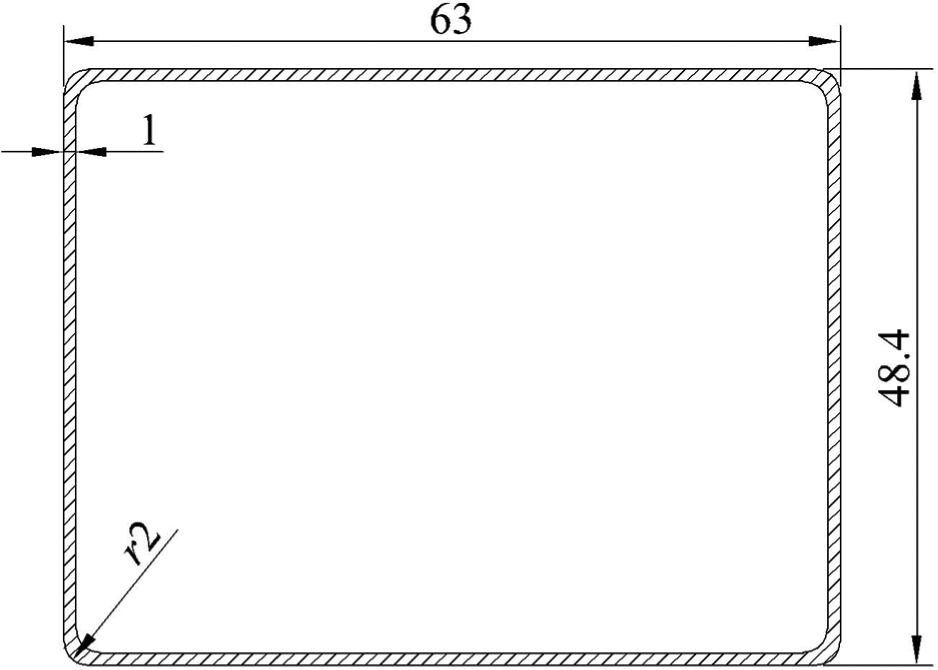
Target section dimension (unit: mm).
Numerical modeling
ABAQUS/Explicit version was used to study the forming process and predict the fracture of the tube. In the finite element model (shown in Figure 7), half of the tube was actually analyzed due to the geometric symmetry. The dies were assumed to be rigid bodies, while the tube was defined as a deformable body with hexahedral elements (C3D8R). A penalty-based contact algorithm between tube and dies was used, and the coefficient of friction was defined as 0.05, 0.1 and 0.15. The whole forming process contained two steps: die-closing and hydro-forming.
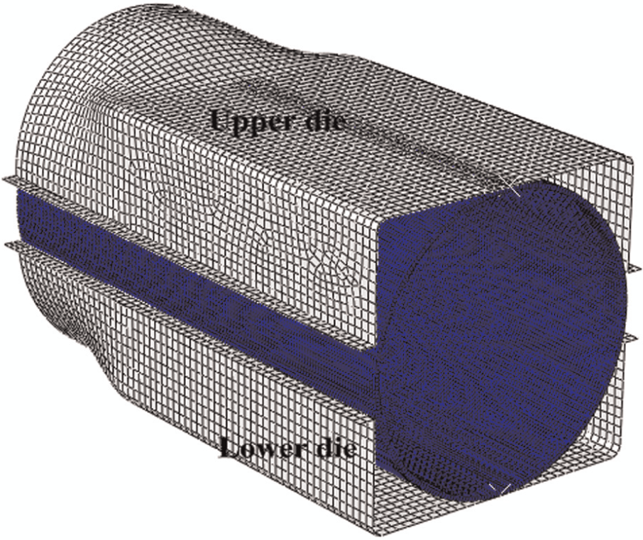
Finite element model.
Deformation model setup for corner filling behavior
A previous study by Nikhare et al.
28
has shown that the arc on the corner during deformation stayed circular with a negligible geometrical error. Hence, a perfect circular arc was assumed. A quarter rectangular model of the process during corner filling was established as shown in Figure 8. At any given step of the deformation, the tube section can be divided into three parts: sticking zone, sliding zone and corner zone. The contact length consists of sticking zone and sliding zone. When internal pressure is applied on the inner surface of tube, the circumferential force
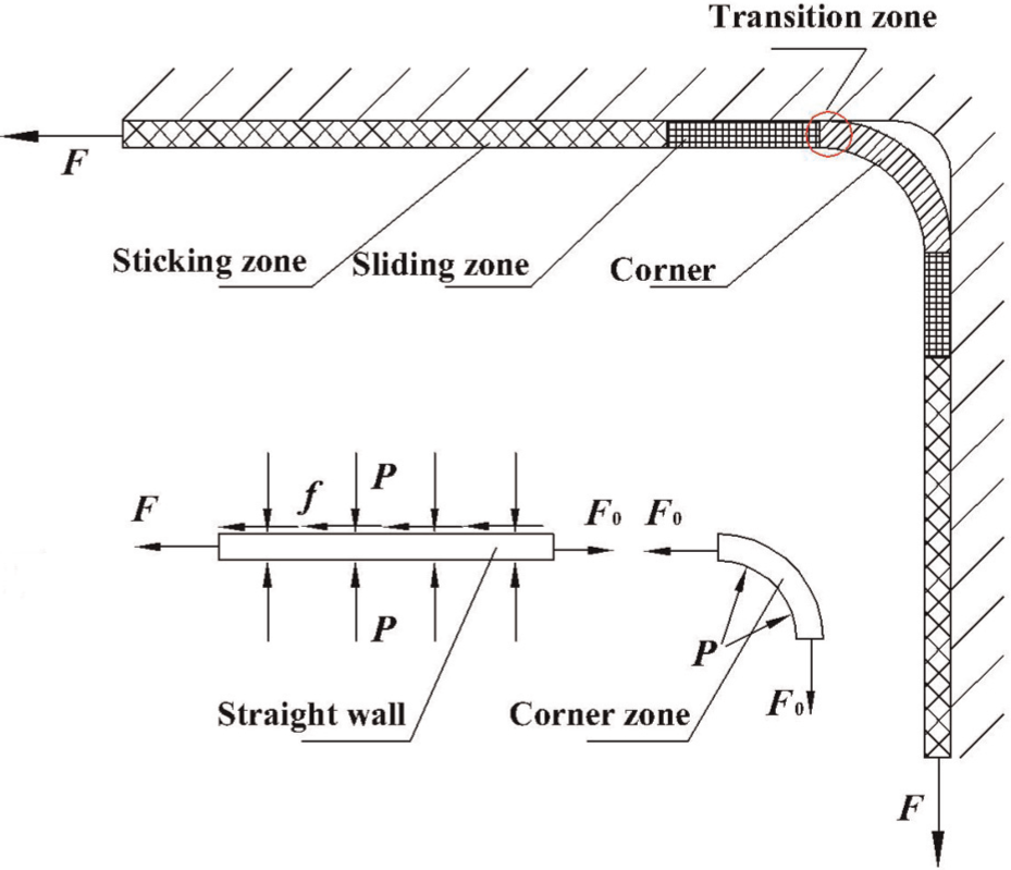
Model of corner filling behavior.
Results and discussion
Figure 9 shows the simulation and experimental results under the condition of different coefficients of friction. For
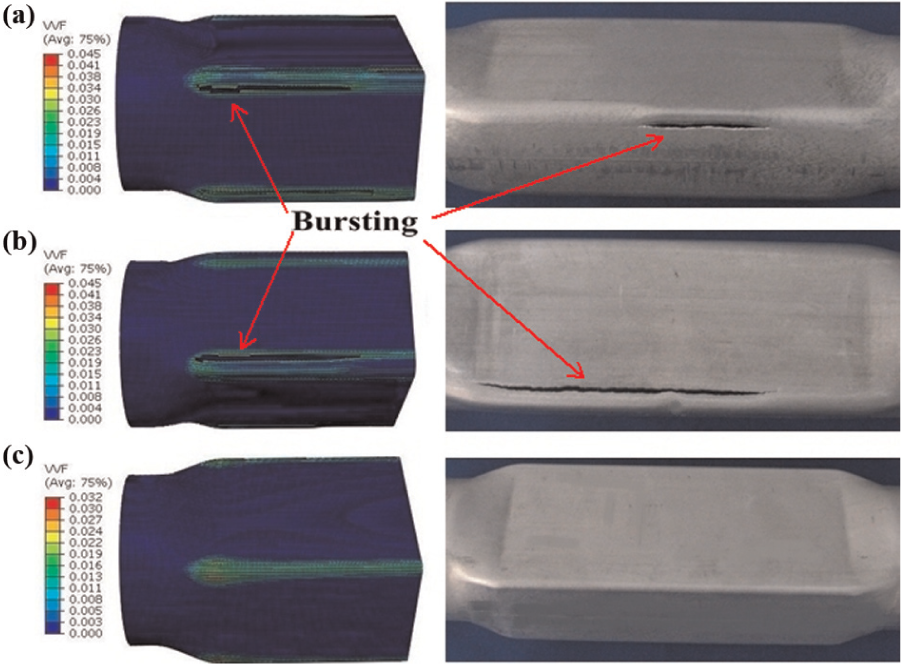
Deformation for different coefficients of friction: (a) µ = 0.15, (b) µ = 0.10 and (c) µ = 0.05.
Figure 10 shows the effect of coefficient of friction on corner filling behavior during hydro-forming process. When the dies are closed, partial tubes have contacted with the dies. As the internal pressure increases beyond yielding, the corner radius decreases, and the contact length between the tube and the dies increases. At the beginning of hydro-forming, the internal pressure is relatively low, so sliding zone prevails all over the contact length. The sticking zone starts at a middle stage of the deformation, and the pressure when sticking friction starts decreases as the coefficient of friction increases. Sticking zone grows until it takes over the whole contact length, which is named full sticking. Once the whole contact length turns to sticking zone completely, the void volume fraction value increases rapidly to the failure porosity value
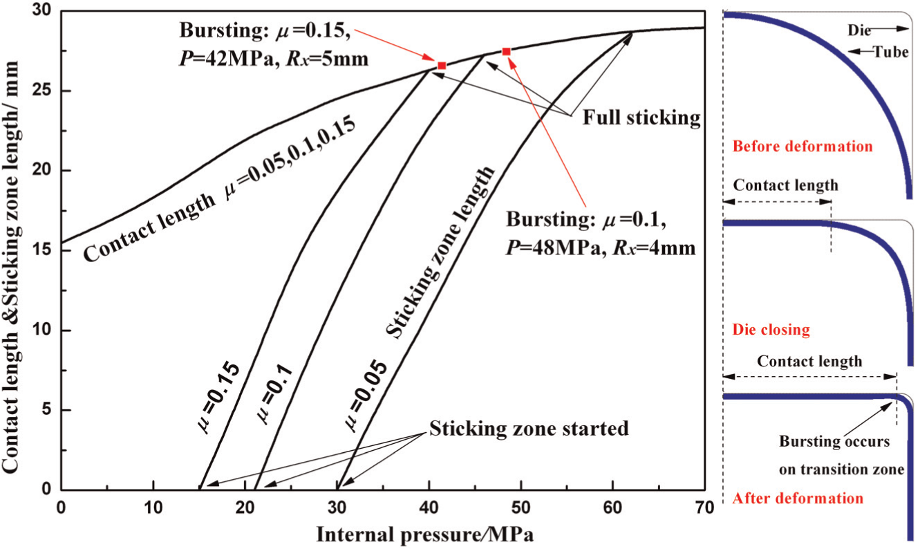
Effect of coefficient of friction on the variation in sticking zone during tube hydro-forming.
As the deformation progresses, the thickness decreases. The maximum thinning location is at the transition zone where joins the straight wall and corner. The variation in the thickness at the transition zone with corner radius in simulation is shown in Figure 11, and the full sticking positions are also marked. Before full sticking occurs, both a sliding zone and a sticking zone exist, and the material could stretch any further as the internal pressure increases. So, the thickness located at transition zone varies slowly. Once full sticking prevails, the thinning becomes very sharp and bursting is more likely to occur. It also can be seen that as the coefficient of friction increases, stretching is more localized at the transition zone, which leads to a greater thinning.
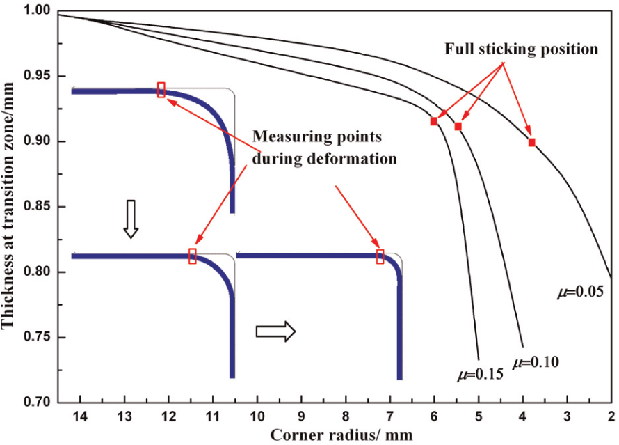
Variation in thickness at transition zone.
Strain paths of the points located at the transition zone in the FLD are also shown in Figure 12. In addition, the FLD is obtained by tube bulging test with different boundary constraints such as fixed-end, free-end and forced-end.29,30 As the coefficient of friction varies, the final positions of strain paths in the FLD are different. For
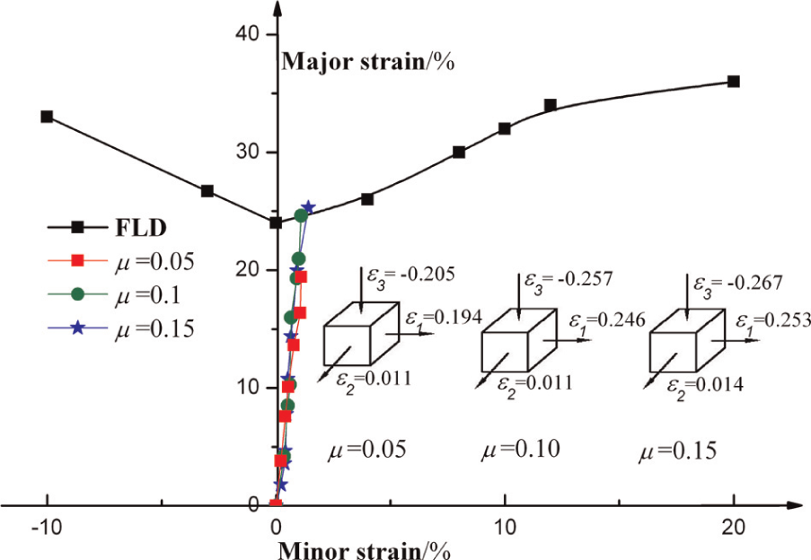
Strain paths of typical element located at transition zone.
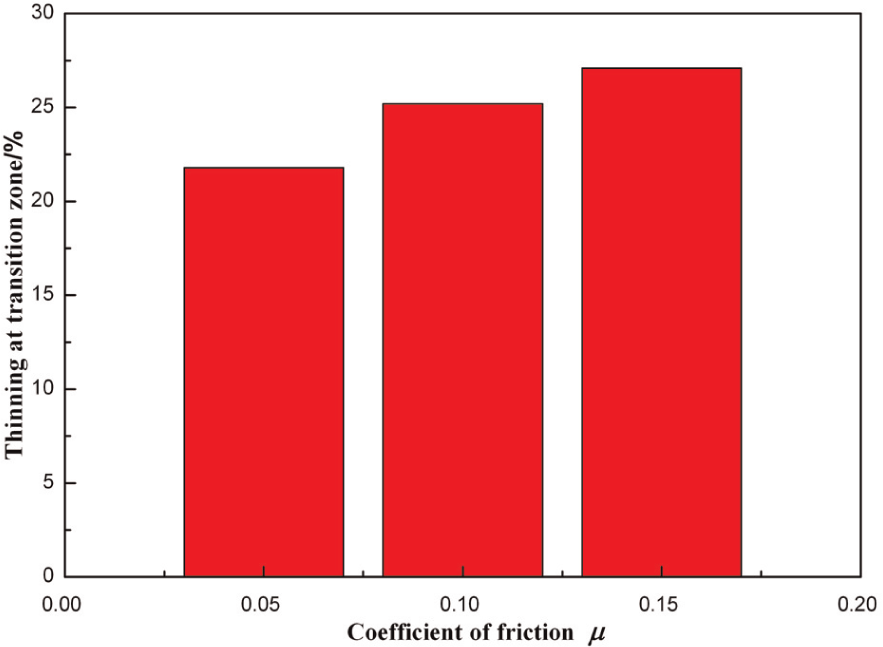
Maximum thinning in experiments.
Figure 14 shows the variation in corner radius with the internal pressure under the condition of different coefficients of friction in experiments. It can be seen that after die-closing, the corner radius is between 14 and 15 mm, which is in agreement with the value calculated by equation (6). For
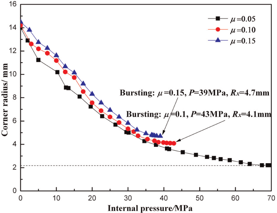
Effect of coefficient of friction on corner radius in experiments.
Figure 15 shows the variation in displacement sensor
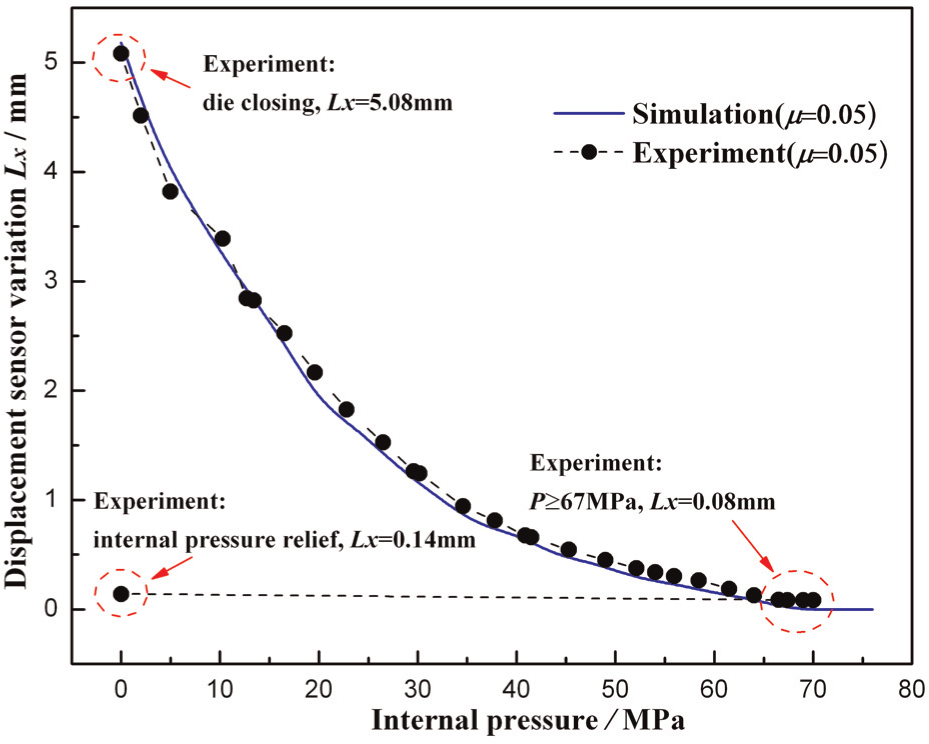
Variation in displacement sensor in experiments and simulation.
Conclusion
GTN ductile damage model was used to study the effect of coefficient of friction on the deformation variables and predict fracture. The varying trend analysis of the tube deformation behavior in experiments and simulation under the condition of different coefficient of friction showed that the model established to describe the corner filling behavior was appropriate. The increase in the coefficient of friction would lead to greater variation in thinning and corner radius, and the variation is obvious when sticking friction prevails. Once the whole contact length is taken over by sticking zone, friction leads to greater thinning at transition zone and bursting occurs rapidly. In experiments, when the coefficient of friction is 0.05, there is an acceptable rectangular section with the corner radius of 2.34 mm and the internal pressure of 67 MPa, correspondingly the maximum thinning at transition zone is 21.8%.
Footnotes
Appendix 1
Declaration of conflicting interests
The authors declare that there is no conflict of interest.
Funding
This article was financially supported by National Natural Science Foundation of China (50975061) and Fundamental Research Funds for the Central Universities (Grant No. HIT NSRIF 201134).