
Abstract
Galling is a severe form of adhesive wear encountered in metal forming operations. In hot stamping, an Al-Si coating is normally applied onto the ultra-high-strength steels to prevent decarburisation and to improve the corrosion resistance of the steel. Material transfer occurring from the coated ultra-high-strength steel to the tool surface has been identified as major issue in hot stamping. This transferred material impairs the quality of the produced parts and at the same time, it increases the costs of maintenance of the tools. This work focuses on the understanding of surface topography parameters and their effect on galling. Surface roughness level and orientation of the surface lay on tool surface have been studied. The results showed that a single parameter of the surface topography is not enough to describe the resistance to galling. Parameters such as Rv, Rp and Rsk are also important to consider in order to rank the galling resistance of the surface. The sliding direction with respect to the surface lay also had a significant influence on galling; sliding in the direction parallel to it resulted in substantially reduced material transfer.
Introduction
The usage of hot stamping, or press hardening, to produce ultra-high-strength steel (UHSS) components for automotive applications has increased tremendously in the last years. This is mainly in view of the possibility to produce complex shaped parts with high strength, which enables reduced weight and emissions combined with improved crash worthiness of the vehicle. An Al-Si coating is often applied to the UHSS that prevents decarburisation during heating and results in a surface with good corrosion resistance. However, there are problems during hot forming of the Al-Si-coated UHSS, which are associated with the coating.
Galling has been identified as a crucial problem during hot forming of Al-Si-coated UHSS. Material transfer from the workpiece to the tool is known to occur during forming of the Al-Si-coated UHSS sheets where thick layers of transferred material can form and impair the quality of the workpiece. During heating of the Al-Si-coated UHSS up to above 900 °C, intermetallic compounds are formed between aluminium and silicon from the coating and iron from the substrate. 1,2 These intermetallics have high hardness, which means that the layers of transferred material on the tool surface contain hard constituents. These surface defects can therefore induce severe wear on the formed components and cause geometrical variations beyond the specifications. In addition to the problems caused by the transferred material, the hard surface of the Al-Si-coated UHSS itself causes wear of the tool surface, further enhancing the problems with tool quality. Another common problem associated with galling is that there is an increase in downtime for refurbishing and maintenance of the tools and this has an adverse effect on the overall economy of the process.
Surface roughness is known to influence the galling behaviour in both dry and lubricated contacts. In his study, Schedin 3 observed that galling has a big tendency to initiate at the irregularities on the surface and larger lumps develop during the forming operations. He states that the action of surface irregularities as initiation sites for galling does not depend on material combinations or lubrication. He suggests that due to the nature of how galling initiates, material transfer cannot be completely avoided and only the growth rate of the transferred layer may be controlled.
In metal forming processes, not only irregularities of the tool surface can act as initiation sites for material transfer. Die corners are regions where temperature and normal contact pressures are high and these tend to be the sites where galling initiates. Hou et al. 4 suggest that high local temperature and normal contact pressure can be of great importance in the occurrence of galling.
In a study done by Podgornik and Hogmark, 5 they observed that polishing of the tools reduces the severity of galling. However, they suggest that surface engineering can bring some benefits, but it needs to be well controlled. They proposed a solution for providing good galling properties where surface modification of the tools should include plasma nitriding, post polishing after plasma nitriding and finally a deposition of a hard low-friction coating.
The occurrence of galling at high temperatures is extremely important, but only a few studies have been carried out to understand galling and to explore ways to overcome this problem. Yanagida and Azushima 6 have studied the performance of different lubricants for hot stamping of UHSS. They found that lubricants help in decreasing the stamping load and the die wear. However, it is not clear whether the use of such lubricants has a beneficial effect in reducing galling during forming of Al-Si coatings. Kondratiuk and Kuhn 7 have studied the wear behaviour of coated tool steels sliding against Al-Si UHSS. They observed that the use of coatings applied to the tool steel had a negative effect on wear of the workpiece and resulted in more severe galling than with uncoated tool steels. They suggested that a way to reduce galling could be to increase the temperature during the austenitisation stage.
The authors have previously studied the initiation mechanisms of high-temperature galling in hot sheet metal forming. 8 It was observed that accumulation and compaction of debris were key features in terms of the severity of material transfer onto untreated tool steels. Minimal galling was observed on polished and milled tool steel specimens as accumulation of debris did not occur as easily as for ground surfaces.
Even though surface roughness of the tool steel specimens has been found to be an important parameter, which strongly influences the galling behaviour, the role of the surface topography in the initiation of galling has not yet been thoroughly analysed. This work is aimed at evaluating the influence of different surface topography parameters, besides the commonly used Ra/Sa parameter, on the occurrence of galling during the tool steel/Al-Si-coated UHSS interaction at elevated temperatures. The parameters considered for this study are Rp, Rv, Rsk and Sm. The primary objective is to identify parameters that can be used to characterise the galling resistance of untreated tool steel surfaces.
Experimental
In this work, tribological experiments have been carried out using untreated tool steel with different surface topographies produced by grinding. Three different grit sizes of SiC abrasive papers were used. As a reference, the surface roughness that is normally achieved after refurbishing an actual hot stamping tool was used. The different surfaces were characterised and the correlation between certain surface parameters and galling was analysed. Furthermore, the influence of the orientation of the surface lay, relative to the sliding direction, was also studied. Tribological tests were done with sliding parallel and perpendicular to the tool surface lay.
Test materials and specimens
The specimens used for the tribological tests were an upper pin of ∅ 2 mm made from quenched and tempered hot work tool steel with hardness of 52 HRC. The chemical composition of the hot work tool steel was the same for all the cases. A similar composition is normally used for tools in the actual hot stamping process. The lower disc specimen (∅ 16 and 1.7 mm thickness) was made from Al-Si-coated UHSS and was welded onto a steel backing plate of ∅ 24 and 6.3 mm thickness. The properties of the Al-Si-coated UHSS have been described by Suehiro et al. 1 Welding of the Al-Si-coated UHSS onto the backing plate resulted in no microstructural changes to the coating or steel microstructures in the region where the tribological tests were performed (centre of the disc specimen).
The surface of the tool steel pin specimens was prepared by grinding using SiC abrasive paper of different grit sizes, #60, #120 and #240. Grinding was done in a single direction with a view to produce a surface lay with a well-defined orientation. This will be referred to as mild grinding. The surface corresponding to the refurbished tools will be referred to as coarse grinding. Table 1 shows the surface roughness parameters and the values that correspond to each test specimen.
Surface topography values of the ground pin specimens.
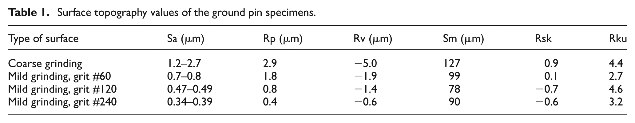
Commonly, the average surface roughness Sa/Ra is used for describing surfaces, but this type of parameter does not provide spatial structure information and does not differentiate between peaks and valleys. Ra is the average surface roughness in two dimensions (2D) and Sa is the equivalent average surface roughness in three dimensions (3D). To evaluate the impact of the information that is not provided by the average surface roughness Sa, additional parameters were analysed. The surface topography measurements were carried out using a Wyko 1100NT 3D optical surface profiler and the data were obtained in 2D. The profiles taken were perpendicular to the surface lay of the pin surface.
Rp and Rv were used as these parameters directly give information about the peak height and valley depth and Rt is the sum of Rp and Rv. Rsk (skewness) and Rku (kurtosis) were also used as they describe the symmetry of the surface distribution. The sign of the Rsk will tell if the farther points are proportionally above (positive) or below (negative) the mean surface level. Thus, it will tell if a surface has predominantly peaks/spikes or holes/valleys. Rku on the other hand gives information about the randomness or repetitiveness of a surface. Similar to Sa, the above-mentioned parameters do not provide information about the spatial structure. To account for this, Sm was used as it describes the mean spacing between profile peaks.
Figure 1 shows the 3D images of the different tool steel surfaces. The surface shown in Figure 1(a) corresponds to a typical surface after coarse grinding of an actual hot stamping tool. Figure 1(b)–(d) corresponds to surfaces obtained after grinding with SiC abrasive papers of grit sizes #60, #120 and #240, respectively. Only specimens with a surface topography corresponding to that shown in Figure 1(a) were used for the studies pertaining to the surface lay.
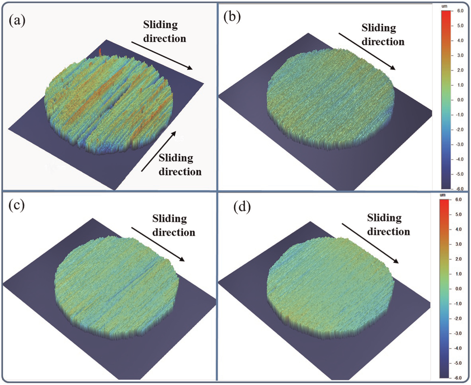
3D optical surface profiler images of pin specimen surfaces after (a) coarse grinding and mild grinding with abrasive paper of grit sizes (b) #60, (c) #120 and (d) #240.
Test equipment and procedure
The experimental work in this study was carried out using an Optimol SRV® high-temperature reciprocating friction and wear test machine. An electromagnetic drive oscillates the upper specimen under normal load against the stationary lower test specimen. The normal load is applied by means of a servomotor and a spring deflection mechanism. The lower test specimen is mounted on a specimen block incorporating a cartridge heater, which enables tests at elevated temperatures of up to 900 °C. A computerised control system enables accurate control of the applied load, temperature, stroke length and frequency of the oscillatory movement. The data acquisition system records friction, temperature, load, frequency and stroke length during the tests. The temperature is measured in the heating block, but since the test specimens are made from steel with good heat conductivity it can be assumed to have approximately the same temperature. The test conditions used for the tests carried out in this work are given in Table 2.
Test parameters.
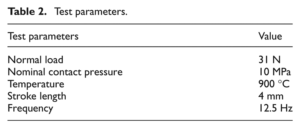
Before the tests, all specimens were cleaned with ethanol. The upper pin specimen was kept separated from the lower disc during heating and the holding time. This means that the Al-Si-coated UHSS specimens were at 900 °C and the tool steel specimens at a much lower temperature (∼200 °C) at the beginning of the tests. The reason for the increased temperature of the tool steel specimen is radiation from the heated Al-Si-coated steel within the test chamber.
The specimens were kept separated during heating with a view to simulate the hot forming process, in which the workpiece is first heated up and then it comes into contact with the relatively colder tool. Once the desired temperature was reached (900 °C), the lower (Al-Si-coated UHSS) specimen was retained at that temperature for 4 min to allow sufficient time for the diffusion of the Al-Si coating while still separated from the upper (tool steel) specimen. The holding time was determined in the laboratory through trial tests with a view to obtain a similar microstructural evolution of the coating as in the actual stamping process. When a time of 4 min had elapsed, the pin was loaded against the disc and the test was started. On completion of the test, the specimens were left to cool in air and then removed and analysed.
For the study concerning the influence of surface roughness parameters, the tribological tests were carried out with perpendicular sliding to the direction of the surface roughness lay of the tool steel specimens, as shown in Figure 1. The experiments to study the impact of the surface lay were done with sliding parallel and perpendicular to the grinding marks of the tool steel surface.
The worn surfaces of the test specimens were analysed using scanning electron microscopy (SEM) coupled with energy-dispersive spectroscopy (EDS). These analyses were carried out using a JEOL JSM 6460LV scanning electron microscope. Furthermore, surface profiles of the worn tool steel specimens were measured by means of a Wyko 1100NT 3D optical surface profiler.
Results
Frictional behaviour
The frictional behaviour of repeat tests is shown in Figure 2. Slight differences, depending on the surface roughness, were observed. For the case of the coarse ground specimens, the friction coefficient started at around 0.6 and then gradually increased up to 0.8. The same behaviour was observed when sliding was carried out perpendicular as well as parallel to the surface lay.
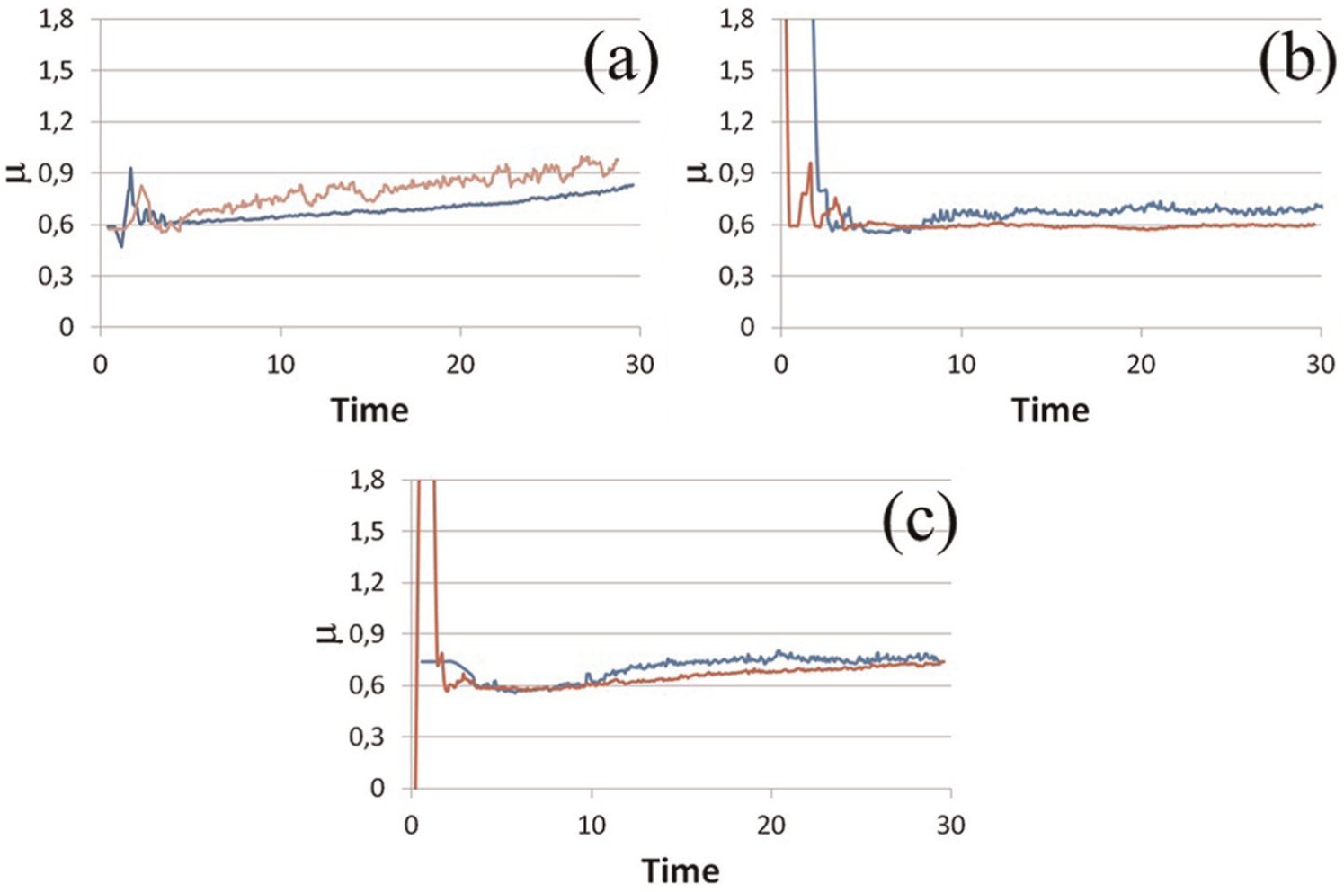
Frictional behaviour of the (a) coarse ground specimen, (b) grit #60 ground specimen and (c) coarse ground specimen with parallel sliding (repeat tests shown for each type of surface).
In the case of the surface ground with abrasive paper, the friction coefficient remained stable for the whole duration of the test. In Figure 2, the curve belongs to the pin ground with grit #60; however, a similar behaviour was encountered for all the other specimens ground with abrasive paper.
Galling
Figure 3 shows a comparison of the four different ground surfaces after the tribological tests. The dark zones correspond to the transferred material from the Al-Si coating. As can be observed, the coarse ground specimen showed severe material transfer and most of the tool steel surface was covered by transferred Al-Si. Surprisingly though, in case of the mild ground specimens, regardless of the grit size, very little material transfer occurred.
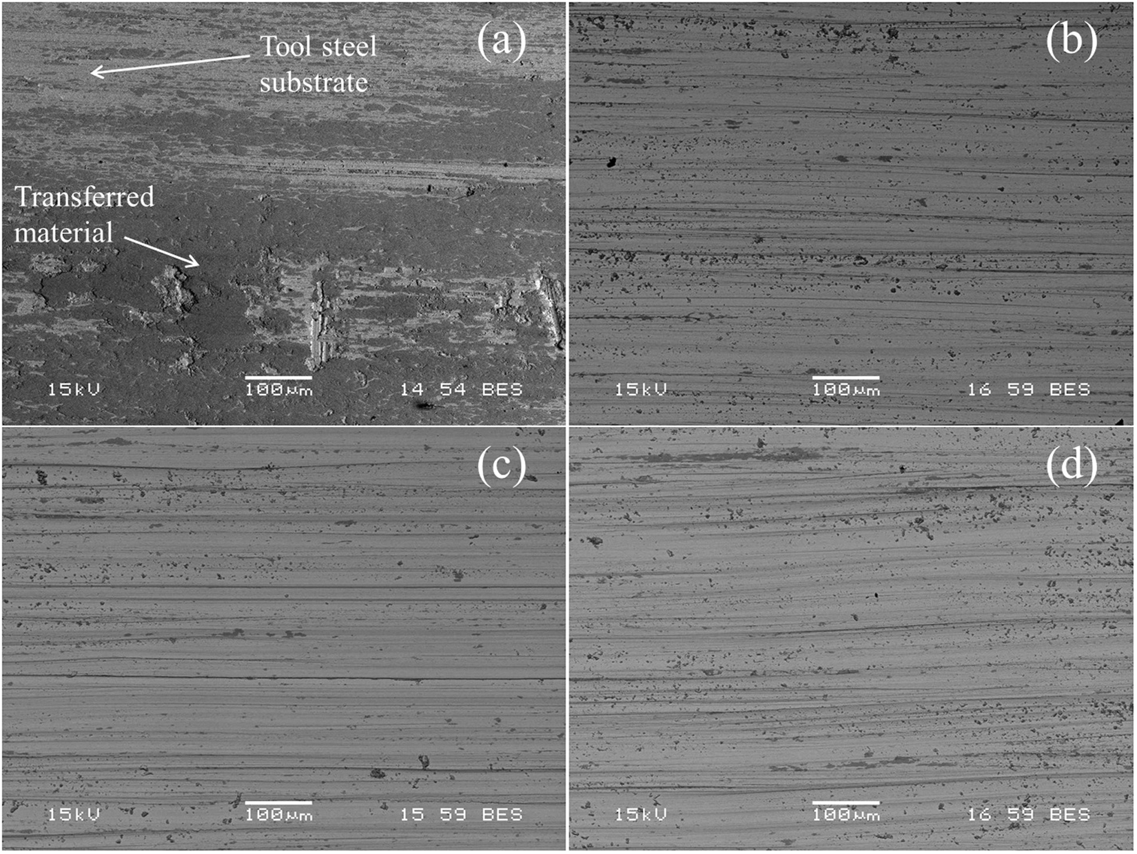
SEM micrographs of the tool steel specimens after the tests: (a) coarse ground, (b) mild ground grit #60, (c) mild ground grit #120 and (d) mild ground grit #240.
All the specimens showed features of abrasive wear and the mild ground specimens had randomly distributed adhered material. The appearance of the surfaces ground with abrasive paper was quite similar; only for the case of the coarse ground specimen, a thicker transferred layer could be observed; this layer also covered a large part of the tool steel surface.
With a view to further understand the role that the surface topography plays in the occurrence of galling, the surface lay was considered. Figure 4 shows the results from the tests involving different orientations of the surface lay. The specimens used for these experiments were coarse ground which, as shown in Figure 3, presented the most severe galling.
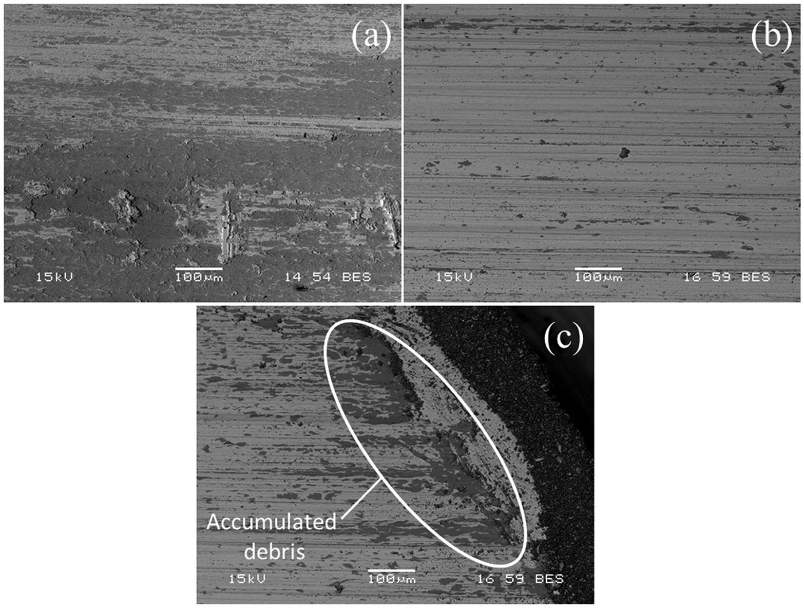
SEM micrographs of the worn tool steel specimens: (a) perpendicular sliding to the surface lay, (b) parallel sliding to the surface lay orientation (middle) and (c) parallel sliding to the surface lay (edge).
The micrographs show a considerable difference between the two specimens despite having the same Sa value (∼2 µm). Severe material transfer was observed when sliding was done perpendicular to the surface lay (Figure 4(a)). In the case of the specimen that slid parallel to the surface lay, very little galling occurred at the centre of the specimen (Figure 4(b)) and the presence of dark zones was almost negligible. At the edge of the contacting surface, larger presence of dark zones was observed and wear debris was accumulated outside the area of contact (Figure 4(c)).
Using the sharp contrast in the micrographs obtained with the backscattered electron (BSE) signal, an approximation of the material transfer could be calculated. The method used for the quantification is given in Figure 5. In SEM images, dark grey corresponds to the transferred Al-Si coating and light grey corresponds to the tool steel (Figure 5(a)). By post-processing the grey scale image, the zones with and without material transfer were distinguished (Figure 5(b)). The dark areas can then be isolated, thus showing only the zones where the transferred material is present (Figure 5(c)). Using this method, the covered area ratio can be calculated.
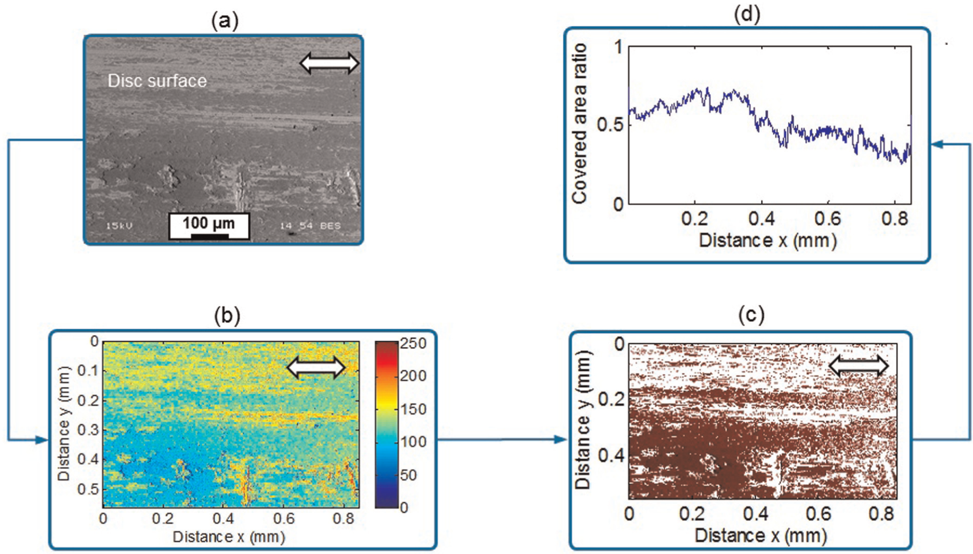
(a) BSE micrograph of the tested tool steel, (b) grey scale differentiating zones with and without material transfer, (c) image processing to extract the dark grey zones and (d) calculated covered area ratio.
A summary of the covered area percentage after the different tribological tests is given in Table 3. Using surfaces prepared with abrasive paper resulted in reduced material transfer compared to the coarse ground surface. More importantly, however, the fact that when the coarse ground specimen slid parallel to the surface lay orientation, the amount of material transfer was of similar magnitude compared to the specimens ground with abrasive paper.
Covered area percentage after the tribological tests.
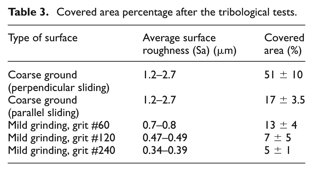
It is important to note that for specimens ground with abrasive paper, as the surface roughness (Sa) decreased the covered area value also decreased. However, these small reductions in the value of the coverage can be difficult to assess. Shadowing effect from surface peaks and loose debris on the micrographs of the surface can affect the measurement.
Wear mechanisms
Wear of the tool steel
As previously mentioned, the tool steel specimens underwent abrasive wear when sliding against the hard Al-Si-coated UHSS at elevated temperatures. 3D optical profiler images of the worn surfaces are shown in Figure 6, and the values of some surface topography parameters after the tribological tests are given in Table 4. All the specimens developed a new surface lay due to the occurrence of abrasive wear and it was aligned parallel to the sliding direction. An interesting observation was that the surface topography of the tool steel after the tribological tests became very similar for all the different specimens, and only the coarse ground tool steel that slid perpendicular to the surface lay showed traces of the original surface lay.
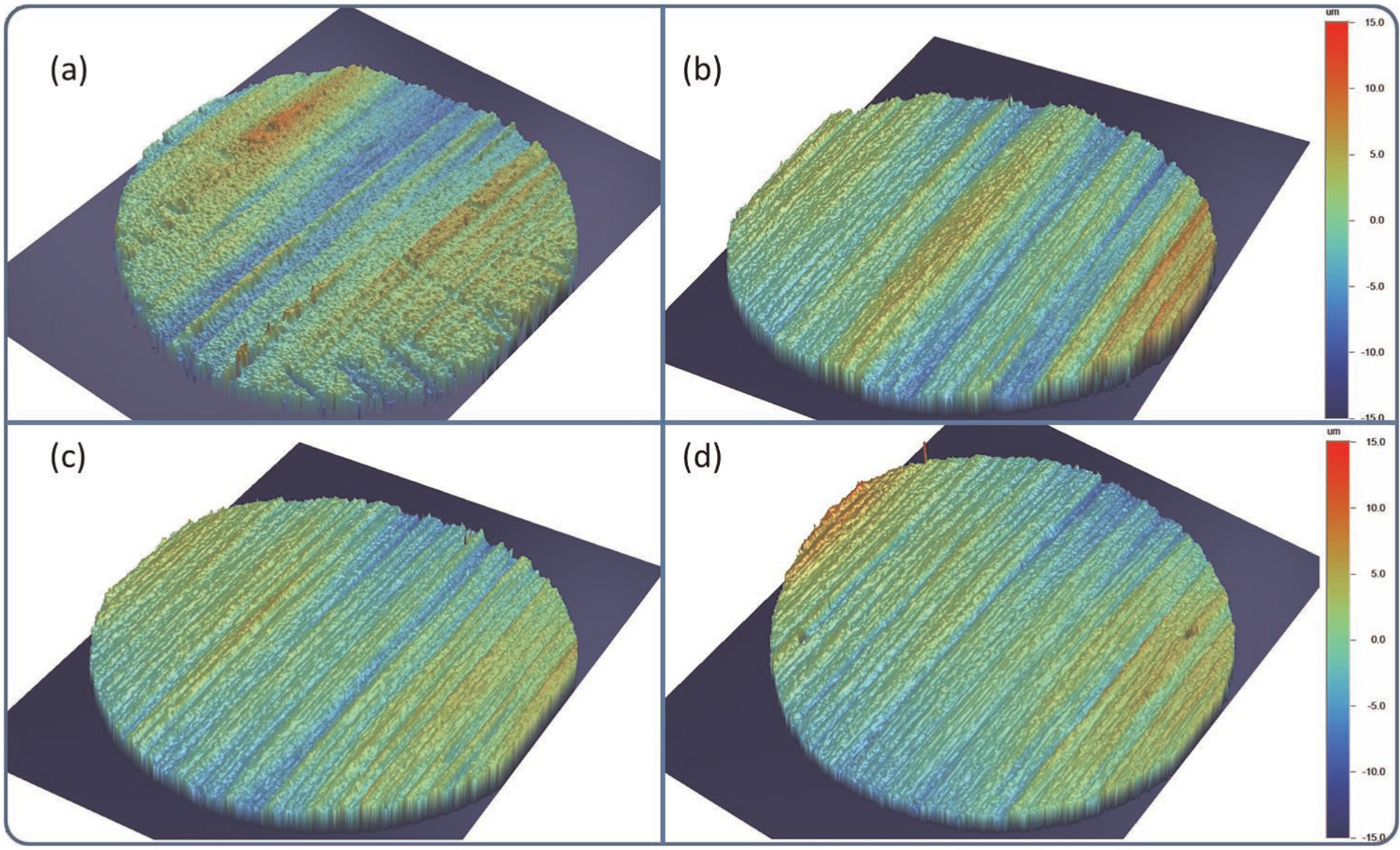
3D optical surface profiler images of the worn tool steels: (a) coarse ground slid perpendicular, (b) coarse ground slid parallel, (c) ground with #60 abrasive paper slid perpendicular and (d) ground with #240 abrasive paper slid perpendicular.
Surface topography values of the ground pin specimens after tribotests.
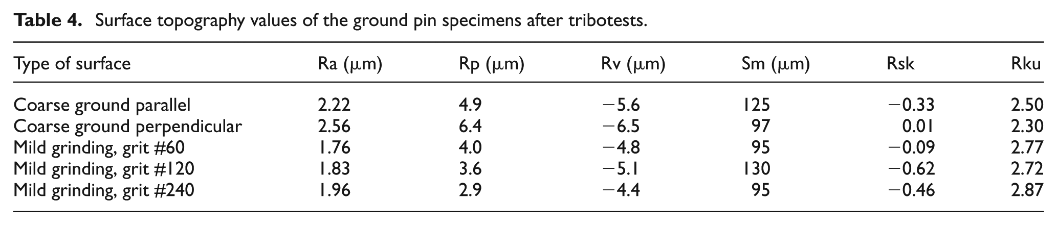
The specimens ground with abrasive paper developed similar values on the different parameters. For the coarse ground specimens, sliding parallel and perpendicular, the average surface roughness did not change as much but the Rsk and Rku did change, from 0.9 to −0.33 and from 4.4 to 2.5, respectively. The Rku value was similar for all the new surfaces formed which indicates that a similar type of texture is generated after interacting with the Al-Si-coated UHSS.
Wear of the Al-Si-coated UHSS
After the tribological tests, similar wear mechanisms were observed on the Al-Si-coated UHSS specimens for all the different test set-up configurations (Figure 7). No signs of severe wear were observed on most of the specimens. Only when the coarse ground tool steel was used, the presence of severe damage on the Al-Si coating was observed. Abrasive wear and ploughing were only observed on this specimen.
Wear of discs slid against pin specimens: (a) coarse ground (perpendicular to surface lay), (b) ground with #60 abrasive paper and (c) coarse ground (parallel to surface lay).
All the specimens developed the formation of a protective oxide layer on the surface. The layers varied in terms of continuity and in most cases they appeared in the form of patches randomly distributed on the wear scar. The specimen that slid against the coarse ground tool steel had a deep groove formed within the wear scar. This is likely to be related to the severe material transfer of Al and Si onto the tool steel as the material removed from the Al-Si coating, in the form of wear debris, could accumulate on the tool steel surface. Zones with undamaged Al-Si coating could be observed in the wear scars of the other specimens suggesting that these zones were not in contact during the duration of the test. This can be attributed to the high waviness of the Al-Si coating, which is a common aspect of the production process, as well as to the development of the protective oxide layers.
Discussion
In this section, the correlation between the tool steel surface topography parameters with the occurrence of galling will be discussed. Furthermore, the impact of the wear mechanisms of the tool steel and Al-Si-coated UHSS specimens on galling will be explained.
Influence of surface topography parameters on galling
In the study done by reference 8 it was stated that the severe material transfer is caused by accumulation and compaction of wear debris and, to a minor extent, due to direct adhesion between the two materials. The occurrence of galling is commonly associated with the presence of surface defects or high surface roughness. 3,9 In most cases, this is due to the increased adhesion at the asperity contacts due to a rise in the contact pressure. However, in this case, all the surfaces can be considered as rough but only the coarse ground tool steel showed severe material transfer. It is clear that the severity of galling is strongly related to the surface topography, but the conditions for the occurrence of severe galling were not met on the specimens ground with abrasive paper or the coarse ground specimen that slid parallel to the surface lay.
The frictional behaviour did not show sudden spikes of the coefficient of friction, which suggests that no severe adhesion occurred in any of the different tests, and furthermore, the levels were very similar for all the tests. Therefore, the importance of the surface topography lies in the way material transfer is initiated rather than on the frictional behaviour. The high spikes followed by the rapid stabilisation of the coefficient of friction seen in Figure 2 are related to the equipment itself. The first few seconds of the tests can be considered as a stabilisation time for the machine. The readings of the first 3 s of the tests were not taken into account for the analysis of the results as these are strongly influenced by the initial static friction, alignment of the specimens and stabilisation time of the test parameters (load, stroke and frequency).
The above statement is further strengthened if one considers the severity of galling when sliding parallel or perpendicular to the surface lay of a very rough surface. Despite the fact that in both cases, Sa was the highest; the results were entirely different in terms of galling. The reduced galling on the specimen that slid parallel to the surface lay can be easily explained if one considers the initiation mechanisms of galling for this tribopair. For the occurrence of severe galling between the Al-Si-coated UHSS and the tool steel at elevated temperatures, agglomeration and further compaction of wear debris are the key factor. Due to the nature of the test, when the surface lay is orientated parallel to the sliding direction, most of the debris can easily escape the contact through the valleys of the surface lay. This prevents accumulation of debris in most parts of the surface. Only at the very exit of the contact area, the debris could accumulate and it was at this zone where the most severe galling was observed.
From the results, it is clear that surface roughness (Sa) alone is not a clear indicative of the occurrence and severity of galling on the tool steel specimens. In general, a high Sa value suggests a higher probability of galling; however, it is not clear as to what can be considered as a high Sa value. For example, all specimens ground with abrasive paper showed negligible galling. Even though the percentage of area covered by material transfer was reduced upon decreasing Sa, the result was always minimal galling for the specimens ground with abrasive paper compared to the coarse ground specimen that slid perpendicular to the surface lay. The specimen ground with abrasive paper of grit #60 had a surface roughness Sa ≈0.75 µm. For many applications, this value of Sa can be considered as a rough surface, but nevertheless, in this case, it resulted in reduced galling.
In a study done by Podgornik and Jerina, 9 they suggested that Rsk and Rku roughness parameters can be used to classify the galling resistance of austenitic stainless steel against a cold work tool steel. A ‘load-scanning test rig’ was used in their work and the tests consisted of sliding a stainless steel cylinder against a stationary tool steel cylinder of interest. Single-pass tests were performed under dry and lubricated conditions with a gradually increased load, which resulted in a nominal contact pressure between 1.3 and 5.2 GPa. They proposed that with a more negative Rsk value and a high Rku value, a better galling resistance is observed and their importance is amplified when lubricants are used. In the tool steel/Al-Si-coated UHSS system, the specimens with lower Rsk value showed less material transfer but the Rku does not show a clear correlation with galling. The difference between the results observed here and the ones observed by Podgornik and Jerina 9 is that the mechanisms for initiation of galling are different. In this case, adhesion is not the main contributing factor for severe galling; hence, the parameters that influence it are different.
The high material transfer on the coarse ground specimen can be explained if one considers the surface parameters, as shown in Table 1. The coarse ground tool steel not only presents a high Sa value, parameters such as Rv, Rp, Sm and Rsk can be used to determine whether the surface of the tool steel has potential sites where galling can be initiated. In Figure 8, these surface parameters are highlighted. The combination of high Sm (mean spacing of peaks) and high Rv (maximum profile valley depth) or high Rvk (average valley depth) provides with large sites where debris can be accumulated, compacted and then develop as thick lumps of transferred material on the surface. High Rp (highest peak height) means that the peaks that cause wear on the Al-Si coating are also available for a longer time during sliding and generate higher amount of Al-Si wear debris. It is important to note that in this case, the Sm value of all the surfaces was sufficiently large to allow the wear debris to accumulate inside the valleys and the reduction of galling was mainly associated with the reduction of Rv.
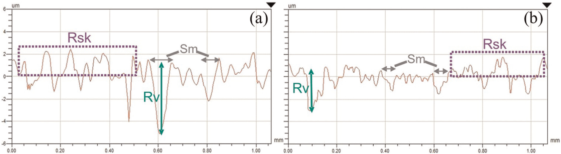
Comparison of relevant parameters for occurrence of galling: (a) coarse ground surface and (b) mild ground specimen.
It was observed that Rsk did not show a clear tendency with respect to the occurrence of galling. However, the magnitude (absolute value) of the parameter can be used in conjunction with the valley depth (Rv) and peak height (Rp). If the absolute value of Rsk is high, this means that the peaks or valleys are very high or very deep, respectively. If one considers that valleys and peaks are sites where debris can accumulate, a high absolute value of Rsk would imply that the peaks and valleys will take longer time to wear off and potential sites for accumulation of wear debris are available, thereby leading to occurrence of galling.
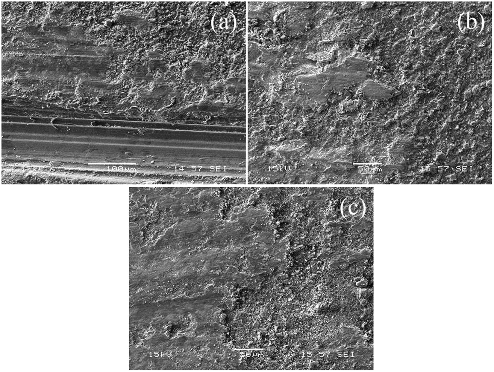
The debris accumulation inside the surface valleys is shown in Figure 9. The figure also shows a detail of a place where the debris is being compacted. It is clear from this image that the controlling feature for the occurrence of galling is the availability of sites for accumulation of debris (Rv/Rvk). As seen in Figure 9, once a transferred layer is formed, debris can easily accumulate and compact at its edges. This suggests that the rate at which galling occurs increases progressively with the formation of transfer layers.
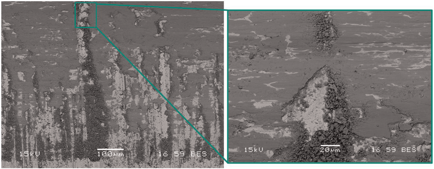
SEM micrographs of surface features where wear debris accumulates and gets compacted.
Influence of oxide layers on galling
A cross section of the oxide layers formed on the surface of the Al-Si coating is shown in Figure 10. The EDS of the layer revealed the presence of oxygen and chromium, a unique constituent of the tool steel, which suggests that the layer is formed primarily by oxidised wear debris coming from the tool steel. The tribolayer is dense and well compacted, features commonly observed in layers known as glaze layers. 10 The protective oxide layer is well adhered to the Al-Si surface and quite thick (∼18 µm), which would explain the good protection against wear that it provides to the Al-Si coating surface.
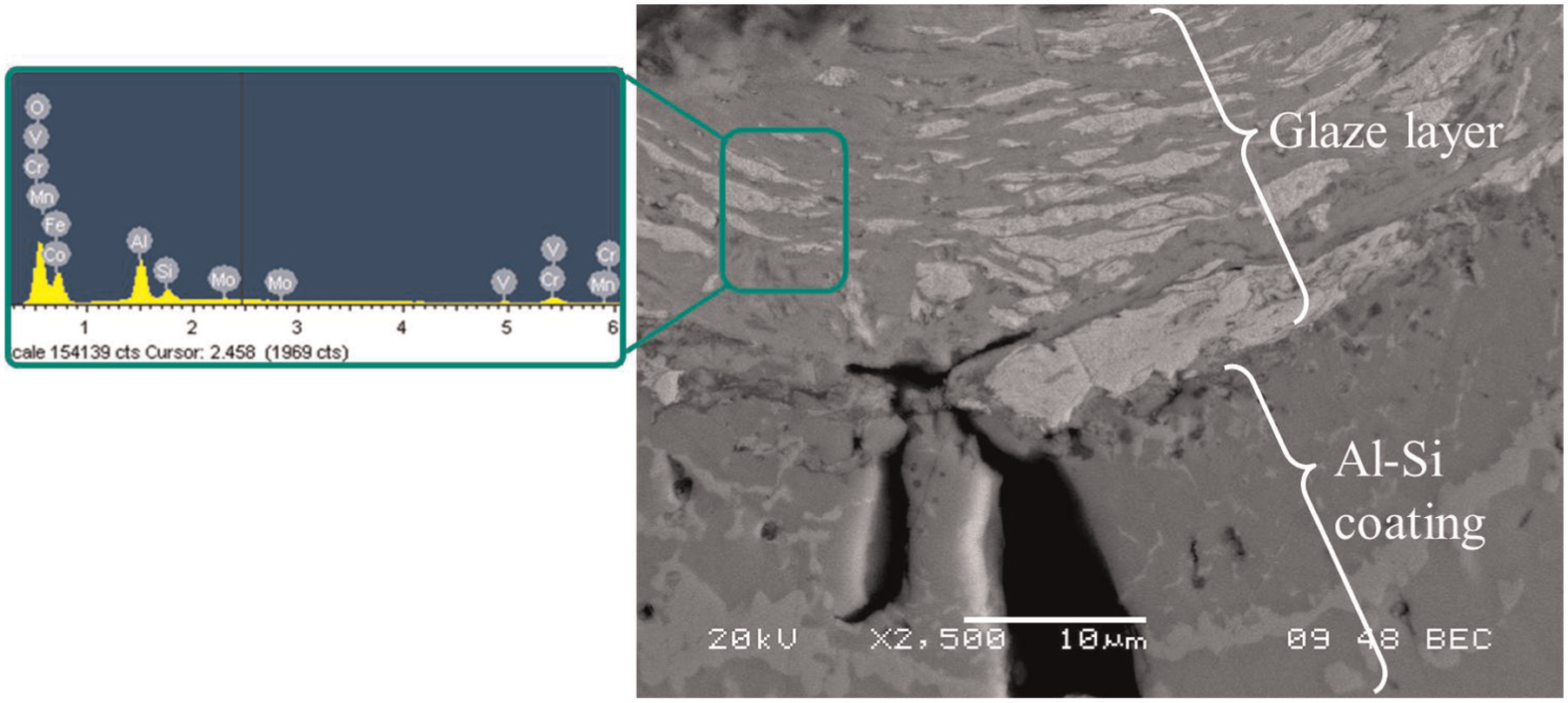
SEM cross section of a protective glaze layer formed on the Al-Si coating surface.
The existence of the glaze layers suggests that there are two effects occurring simultaneously: on one hand, the accumulation and compaction of the wear debris on the tool steel surface, which occurs easily on the coarse ground specimen, and on the other hand, the formation of the protective glaze layer on the Al-Si coating surface. In the case of the mild ground specimens, the glaze layer could be responsible for the limited amount of adhered material on the pin surface. In the case of the coarse ground specimen, however, when the transferred material on the pin surface interacts with the glaze layer on the disc, the protective layer is damaged, thus generating more severe wear on the Al-Si-coated UHSS specimen and enhancing the severity of galling.
Analysing the wear mechanisms of the tool steel specimens, the total damage mechanisms on both specimens (tool steel and Al-Si-coated UHSS) can be explained. The reason for the occurrence of a more severe galling on the coarse ground tool steel is that the sites where debris accumulates are available for a long time during the test, and hence, material transfer can easily occur. In the case of the tool steel ground with abrasive paper, the surface lay was worn off and a new lay was produced by sliding against the hard Al-Si coating. The wear debris generated from the tool steel oxidises due to the elevated temperature of the test and forms the glaze layers on the Al-Si coating surface, which protects the coating from further wear and thus reduces the severity of galling.
The above-mentioned hypothesis does not occur for the case of the coarse ground tool steel specimens. Since material transfer takes place onto its surface, the hard transferred material is able to damage the glaze layer. Thus, wear of the Al-Si coating is not prevented and galling can take place as wear debris from the coating is continuously being generated.
Conclusion
High-temperature tribological studies have been performed to investigate the influence of tool steel surface topography on high-temperature galling during sliding against Al-Si-coated UHSS. The salient findings from this study are as follows:
The surface roughness of the tool steel obtained after grinding with different grit sizes of abrasive paper resulted in reduced galling at elevated temperatures.
The orientation of surface roughness lay with respect to the sliding direction significantly influences the galling behaviour. Parallel sliding with respect to the surface lay tends to reduce material transfer and the galling tendency.
Surface roughness parameters such as Rsk, Rv, Rp and Sm have a strong influence on the occurrence and severity of the transfer of the Al-Si coating onto the tool steel.
Formation of protective glaze layers on the Al-Si coating significantly reduces the severity of material transfer through a reduction of wear of the Al-Si coating.
Footnotes
Acknowledgements
The authors are grateful to Gestamp HardTech AB for their keen interest in the realisation of this work.
Declaration of conflicting interests
The authors declare that there is no conflict of interest.
Funding
This work was carried out with financial support from the Centre for High-performance Steel (CHS) and Gestamp HardTech AB.