
Abstract
Drilling is one of the machining processes most used by manufacturing companies and is very complex from the perspective of scientific study. The geometry and the surface are generated in a single operation with many influential parameters. Geometric and dimensional control are more critical when the use of cutting fluids is reduced or eliminated because the temperatures in the process can influence the shape and the dimensional accuracy of the holes. However, this influence is not completely understood. With this goal, this article presents a dimensional analysis of holes made with carbide drills in AISI P20 steel under the fluid application of emulsion, minimal quantities of lubricant and dry machining. The dimensional parameters analyzed were the diameter and the circularity of the holes. Special highlight can be given to shape results, which were evaluated at different depths (beginning, middle and end of the hole), and along the evolution of the number of holes. Some differences of the investigated results compared to the literature are due to the formation of adhesion on the wall of the hole, resulting from passage of the edge on this particular severity condition.
Introduction
Drilling is one of the most commonly machining processes used in manufacture operations and represents approximately 30% of all machining processes. 1 The drilling process is executed under relatively severe conditions, for example, cutting speed ranging from 0 in the chisel edge region to maximum at the periphery of the edge, and the cutting fluid, which should act as coolant, lubricant and support to chip transportation, does not come to shear cutting zone and has inadequate heat distribution. 2
The mechanical work effectively employed for the machining is mostly transformed into heat, and the main sources are in the regions of shear and friction zones. As a consequence, there is an increased wear at the cutting edges, directly affecting the dimensional accuracy. In drilling operations, high temperatures can also affect the process of removing chips from the hole, due to increased plastic deformation and the consequent higher packing factor. In extreme cases, it can result in the obstruction of the flutes and drill breakage. Thus, high temperatures in drilling can affect shape, dimensional accuracy and subsurface structure of the holes.2–4 Workpiece thermal distortion is critical to the part dimensional accuracy and quality control. The distortion is often caused by workpiece thermal expansion due to the conduction of heat from the tool–workpiece interface and the accumulation of high-temperature chips on the workpiece surfaces. 5
An alternative historically used to reduce the tool wear is the application of cutting fluids. However, research aimed at reducing or eliminating the conventional use of fluid is a major focus nowadays, due mainly to high environmental standards. The development of new tool materials, accompanied by improved technical characteristics of machine tools, allows the reduction and/or elimination of cutting fluids through the techniques of minimal quantities of lubricant (MQL) and dry machining.2–4
But besides the amount of fluid applied, the application method has great importance in the drilling process, due to the limited ability of the fluid to penetrate in the hole during the process. When the hole depth exceeds 1.5 times the diameter of the tool, the fluid access to the cutting edges becomes difficult due to the confinement of the cutting region, the dynamics of the drill and the counterflow of the chip. The breakage and removal of the chips are more difficult. Thus, for these depths, the application of fluid without the use of an intermittent cycle involving retreat of the tool does not provide significant advantages in terms of cooling and lubrication of the tool.6–9 This severe condition can significantly influence the shape and dimensional accuracy of machined holes.
Dimensional accuracy is recognized as a key element for competitive production due to required tolerances in parts for new and high-tech applications. 10 There are many factors that directly influence the final part quality and may cause dimensional and shape deviations. 11 The cutting temperature is a very important factor in the investigation of tool wear, surface integrity and dimensional accuracy of machined parts. 12 But the thermal effects are only a fraction of the various factors influencing the quality of holes, such as cutting parameters (cutting speed, feed rate, depth of cut), material and coating of the tool, tool geometry, tool clamping, type and method of cutting fluid application and drilling strategy (direct or intermittent, through hole or blind).1,7,13–16
Therefore, the quality of a hole is given by a summary of errors due to the thermal regime in the drilled part and errors due to the dynamics of the process. The mechanisms that induce these errors include drill entry into the piece, deviations in the dynamics of the drill due to the unbalance of forces, errors due to process failures, errors due to cutting by the tool margins and errors due to thermal expansion of the drill and the part. 17
Some previous works addressed the dimensional analysis in drilling with different cooling/lubrication conditions. Braga et al. 18 compared the performance of uncoated and diamond-coated carbide drills, using minimal lubrication and emulsion in the drilling of aluminum–silicon alloy (SAE 323). In their analysis, they evaluated the surface quality of the holes, including diameter, roundness, surface roughness and taper. Their main conclusion was that holes obtained with the MQL system presented either similar or better quality than those obtained with emulsion. Brandão et al. analyzed the hole quality (surface roughness, diameter error, circularity and cylindricity error) on AISI H13 hardened steel (53 HRc) using new and worn carbide drills with 8.6 mm diameter and (TiAl)N coating. They used two levels of cutting speed (25 and 60 m/min) and three levels of cooling/lubrication systems (flooded, minimum lubrication quantity and dry). Their data indicate that dry machining produced the worst results and their conclusion was that the best hole quality was produced with a higher cutting speed using flooded or minimum lubrication quantity. 19 Coldwell et al. conducted experiments using three-flute carbide drills in dry drilling of 25 mm thick disks of BS L168 aluminum alloy. Uncoated and coated (three different physical vapor deposition (PVD) coatings) drills were applied in the tests. The hole quality was assessed in terms of hole diameter, cylindricity and roundness. Regardless of the coating combination employed, little or no difference was found in hole quality. Initial holes were oversize; however, as more holes were machined in the workpiece, hole size tended to decrease to less than the drill diameter. The authors’ hypothesis is that the coefficient of thermal expansion of the workpiece material governed hole diameter rather than coating performance. 20 Nouari et al. evaluated, among other aspects, the dimensional accuracy of holes produced in dry drilling of AA2024 aluminum alloy using high-speed steel (HSS) and carbide (coated and uncoated) tools. They used three cutting speeds and a constant feed value to produce holes with a depth of 8 mm and a diameter of 6 mm. One of their main conclusions was that an HSS drill is not suitable for dry machining of AA2024 aluminum alloy. 21
Martins et al. evaluated the effect of the tool clamp (hydraulic and thermal interference fit) on the hole diameter and circularity, when drilling a Al-Si alloy with uncoated carbide tools and abundant fluid condition. Higher stiffness of the thermal interference fit method provided better results with respect to hole diameter and circularity. 22
Paiva et al., during drilling in abundant fluid condition of a compact graphite iron (CGI) 450, using solid carbide drills with different coatings (TiAlN/TiN, AlCrN, TiSiN/AlCrN), found contrary results regarding the coating application. The obtained results show that the circularity slightly increases with the tool wear, decreases with increasing cutting speed and is directly affected by the type of coating. The authors stated that a higher cutting speed lessens the contact time, and thus reduces the effect of degraded tool cutting edge in the roundness of the drilled hole. 23
Two recent works analyzed the dimensional quality in drilling of cold work steel AISI D2. Aized and Amjad, during the deep drilling with HSS drills (∅ = 8 mm), using abundant cutting fluid, varied the pecking cycle, cutting speed and feed rate. It was observed that the application of small pecks during pecking cycle, in prior to greater pecks, improved the quality of the hole (roundness, cylindricity, diameter error). The authors stated that the observed behavior is due to the exposal of the drill to the cutting fluid, promoting the temperature reduction and chip breaking assistance. 24 Akıncıoğlu et al., in dry drilling with uncoated and coated carbide drills (d = 5 mm), observed that increasing the cutting speed prone to decrease the roundness error (circularity). The authors stated that higher temperatures, due to the increase in the cutting speed, lead to thermal softening of the workpiece material. Therefore, this behavior reduces the shear difficulty, and consequently reduces tool vibration and dimensional error. 25
Three works analyzed the dimensional quality in drilling of stacks formed by composite material and metal layers. A study by Zitoune et al. analyzed hole diameter and circularity in drilling of carbon fiber–reinforced plastics (CFRP)/aluminum stacks without coolant, using plain carbide (K20) drills of various diameters (4, 6 and 8 mm). The composition of the stacks was CFRP (59% Vf, 4.2 mm thick) and Al 2024 (3 mm thick). From the measurements of hole diameter on CFRP, they found that the hole diameter was 10 µm less than the nominal diameter of the drill. Also for the CFRP, the circularity was found to be around 6 µm at low feed rates; when the feed rate was increased, the circularity increased to 25 µm. 26 Shyha et al. performed the evaluation of hole quality in drilling of Ti/CFRP/Al stacks using various uncoated and coated carbide tools with a diameter of 6.35 mm. The workpiece stacks comprised annealed Ti-6Al-4V alloy supported by unidirectional CFRP laminates, under which was a layer of Al-7050-T651 aluminum alloy, and each material was 10 mm thick. When cutting using flood coolant, the three materials presented similar results. In the first hole, the diameter values were near the nominal diameter, while worn drills produced undersize holes. In MQL tests, new and worn tools resulted in oversize holes, mainly for CFRP. 27 Kim and Ramulu evaluated the diameter and cylindricity when performed drilling tests of Gr/Bi-Ti6Al4V stacks using high-speed cobalt (HSS-Co) and carbide drills, with abundant cutting fluid application and variation in cutting speed and feed rate. The results pointed out that HSS-Co tools produced undersized holes, whereas carbide drills produced oversized holes. According to the authors, the increase in cutting speed and feed rate leads to a larger hole, behavior associated with the vibrations on these conditions. Also, higher speeds produced higher cylindricity errors, whereas higher feeds reduced the cylindricity errors. 28
Although there is some literature regarding dimensional analysis in drilling, several aspects remain not completely understood. One of these aspects is the effects of the reduction or elimination of the use of cutting fluids on the dimensional quality of the holes to different depths. At different depths, especially in three points, it is possible to better define a tracing geometrical behavior. Other aspects, such as the effect of the number of hole evolution on the dimensional quality, have not been extensively evaluated. The results of previous works are quite heterogeneous, and no general trends can be established. In the last place, the effect of drilling process on the dimensional accuracy of the AISI P20 steel was weakly considered on the literature and is very important special by moldmaking companies.
Therefore, this study searches for a better comprehension of these effects on hole dimensional quality of the AISI P20 steel, taking as dimensional parameters the diameter and the circularity of the holes. From the diameter results, the shape of the holes can be analyzed, and some shape results found in this study differ from the previous literature.
Methodology
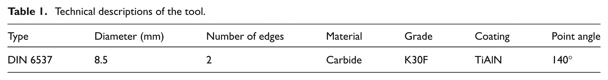
Experimental tests were performed on an Okuma Machining Center, model Ace Center MB—46 VAE, with a maximum speed of 15,000 r/min and a power of 18.5 kW. The workpiece material, with dimensions of 250 × 80 × 40 mm3, was AISI P20 steel, with hardness between 36 and 38 HRc. The cutting tools used in the tests were carbide twist drills (DIN 6537K), model HM ALPHA 2, grade K30, coated with TiAlN and diameter of 8.5 mm, supplied by Walter AG Company. Table 1 presents the main features of the tools.
Technical descriptions of the tool.
For each condition of cutting fluid application—emulsion, minimum quantity lubrication (MQL) and dry—three repetitions were made. Blind holes were machined without center hole, with a depth equal to three times the tool diameter (25.5 mm) and distance between holes of 1.5 times the diameter. The cutting parameters were cutting speed (vc) of 50 m/min and feed (f) of 0.1 mm/rev.
The drilling with emulsion was performed with a continuous strategy, that is, without tool retreat. In this condition, the fluid used was Vasco 1000—provided by the company Blaser Swisslube do Brasil Ltda.—with 10% concentration and flow rate of 1800 L/h, under external application. For MQL condition, the holes were machined with a pecking cycle, with tool motion into and out of the hole and with a cut increment of 1.5 mm. The lubricant used was the synthetic fluid Vascomill MMS (also provided by Blaser), applied with a pressure of 3 bar and flow rate of approximately 10 mL/h through one external nozzle. In dry machining, in addition to the pecking cycle with total retreat of the tool and cut increment of 1.5 mm, the strategy of alternating the sequence of drilling was applied, with a distance between holes of three times the diameter of the drill, taking in this way two cycles to complete the workpiece.
A three-dimensional coordinate measuring machine GageMax model, from the manufacturer Carl Zeiss AG, was used to perform the dimensional measurements. The Coordinate Measuring Machine (CMM) presents a precision of 1 µm, with a resolution of 0.1 µm and uncertainty of 1.3 µm in 600 mm. A spherical probe with diameter of 3 mm and measuring force of 0.15 N was applied to evaluate the diameter and circularity of the holes. The probe scanned the hole wall circumference, obtaining the diameter through median value in Gauss distribution and the circularity.
In order to gain a better understanding of the technological data generated in these experimental tests, dimensional analyses were performed at three different depths (2, 12.5 and 22 mm) for each analyzed hole. Figure 1 illustrates (a) the analyzed regions and (b) shows a picture of the workpiece measurement process.
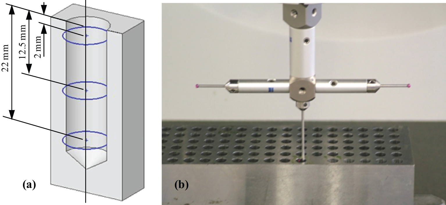
(a) Regions of analysis of the holes and (b) the measuring process.
Results
The following are the results of measurements of diameter and circularity of the holes, as well as the analysis of the effects of cutting fluid application on the results.
Diameter
The method of quantitative verification of the quality of the hole based on H tolerances was used to evaluate the nominal diameter. Figure 2 shows the trend of dimensional deviation under the different fluid application conditions. The registered results were calculated using the average of five equidistant values measured on each analyzed depth.
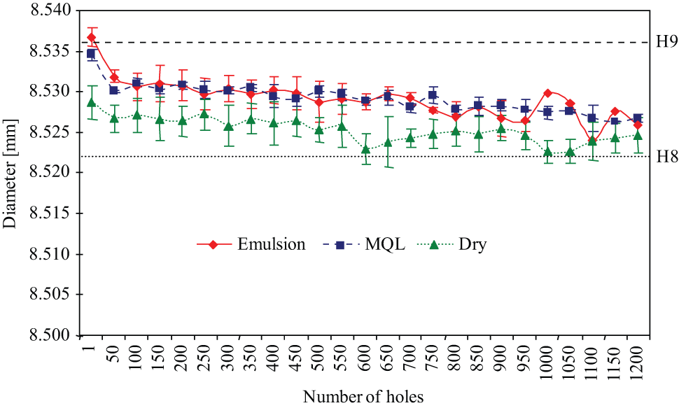
Evolution of the average diameter under different conditions of cutting fluid application.
The holes machined for the three conditions of cutting fluid application were larger than the nominal diameter (8.5 mm), ranging between 20 and 38 µm above the nominal value. Jayal et al. observed the same behavior for the diameter of the hole, during the machining of an aluminum alloy A390.0, with three cutting fluid conditions (flood, MQL and dry). According to the authors, this can be explained by the trapping of abrasive chips between the tool and the wall of the holes, which causes the removal of additional material. 15 Likewise, the machined material used by the cited authors (A390.0 aluminum alloy), the material (AISI P20) and cutting conditions used in this study tend to form small and easy-to-break chips, which in turn benefits the chip flow and thus increases the probability of chip entrapment between the tool and the hole wall.
With the evolution of the number of drilled holes, there is a tendency to diameter reduction, which can be explained by the progressive wear of the tool edges. 26 Experiments conducted by Bossardi et al. 29 in the drilling of cast iron also presented decreased diameter with an increasing number of holes, this behavior being related by the authors with the progressive wear of the drill.
The observed diameter reduction between the first and the last hole is less than 10 µm for the three conditions of cutting fluid application. Therefore, the wear on the margins and corners of the drills, which can lead to diameter reduction of the holes, was small. And since the worn drills presented adhered material on the margins and corners of the drills, it was not possible to measure the wear with the necessary precision. Despite this restriction, it is reasonable to relate the diameter reduction with the drill wear, since this trend was observed for the three tested conditions and is supported by previous literature, as cited above.
The largest measured diameters were obtained when machining with emulsion and MQL, and the results obtained from both conditions remained in the range defined by the tolerance H9 (D = 8.5 mm; −0 + 36 µm). For the dry drilling condition, the analyzed holes presented smaller diameters, when compared to the other tested conditions, and also defined by tolerance H9. The dimensional variations observed between dry drilling and drilling with fluid application are related to thermal aspects and point out the tendency of the fluid not to provide significant improvements on the dimensional accuracy, mainly due to the difficulty in reaching the cutting edges, especially at depths greater than three times the diameter of the tool.
Haan et al. conducted drilling tests of aluminum and also obtained larger diameters with the application of fluid than in the dry condition. The authors suggest that this is due to the cooling properties of the fluid. Without the application of fluid, thermal expansion of the material occurs during machining and, after cooling, the piece contracts, resulting in smaller diameters. 30 According to Klocke et al., in dry machining, there is a longer maintenance of the high temperatures generated in the cut. However, a large portion of the heat is distributed to the chip and the workpiece, since the tool substrate coated with TiAlN is thermally protected due to the refractory properties of this coating. The heat transmitted to the workpiece generates an expansion of the machined material and, with the reduction in the temperature to environment levels at the end of the process, the piece contracts to the registered dimensions. 3 Figure 3 shows the dimensional behavior obtained for the drilling with emulsion at three different depths and the evolution with the increase in the number of drilled holes.
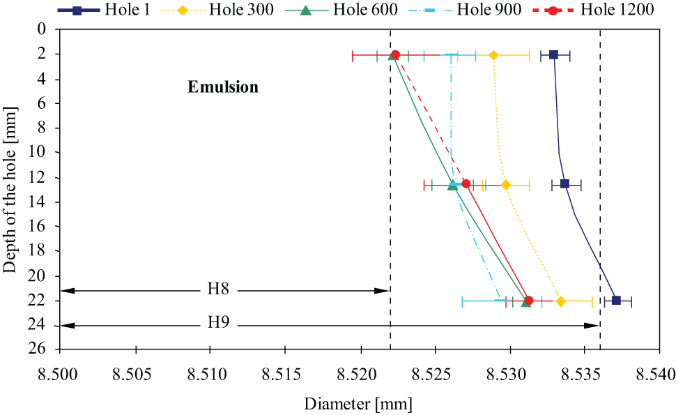
Dimensional behavior with the evolution of the number of holes for drilling with emulsion.
The first hole registered the largest dimensional errors, situated between the depths of 12.5 and 22.5 mm in a range comprised by the tolerance H9, which has been exceeded in the higher depths. For the last machined hole, when compared to the first, the values of the diameter decreased at the three measured depths, and this reduction may be associated with the wear on the tool edges.
In all evaluated holes drilled with the application of emulsion, the same behavior was observed for the dimensional variation with increasing depth. As can be observed in Figure 3, there is a tendency for a smaller increase in diameter between the initial and central regions of the hole, and a greater increase in diameter in the final region, configuring a behavior known as bell-shaped. 13
The bell-shaped holes can be explained by the high temperature during the drilling process. At the beginning of the machining, the drill and the piece have a low temperature. As the drill penetrates in the piece, the heating of the drill and the workpiece material occurs. The drill heats up at the front, leading to an increased diameter of the cutting part of the drill. The region being machined suffers a localized temperature rise. The increased volume of heated material leads to compressive stress in the heated region and to tensile stress in cold regions. These stresses are in balance. As the heated material is prevented from expanding toward the colder surrounding material, the expansion of the workpiece occurs just ahead from the region being cut. When the drill reaches this region of the workpiece, which is already expanded, an additional amount of material is machined. Therefore, after the cooling of the part, the bell-shaped hole is obtained. 31 Figure 4 shows the dimensional behavior at three different depths with the evolution of the number of holes under application of MQL.
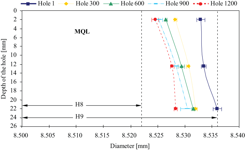
Dimensional behavior with the evolution of the number of holes for drilling with MQL.
The holes obtained for this condition presented, among the three tested fluid application conditions, the best dimensional stability with increasing hole depth, presenting an average variation of 4 µm between the beginning and the end of the hole. This result is possibly related to the joint action of the micro-lubrication, which provides a reduction of the friction between the tool and the workpiece, consequently generating lower temperatures, and of the intermittent cutting strategy with total retreat of the tool, which favors the mist application and the heat distribution along the cylinder. Moreover, according to Heinemann et al., 9 in comparison to the cutting fluids applied in emulsion, the lubricants used in the MQL technique present better thermal stability and greater lubrication capacity. Therefore, better thermal stability leads to maintenance of lubricating properties in environments of high temperatures, ensuring lubrication during drilling of the hole.
The last machined hole presented a reduction of approximately 7 µm when compared to the first. As stated in the previous results, this dimensional reduction may be associated with the effects derived from the alteration of the tool geometry caused by the progressive increase in the thermal and mechanical solicitations on the tool. 7 Such drill geometry alterations impede the material shearing, causing a reduction of the material removed and consequently a reduction in the resulting diameter. Figure 5 shows the dimensional behavior observed for dry machining at three different depths and its evolution as the number of machined holes increases.
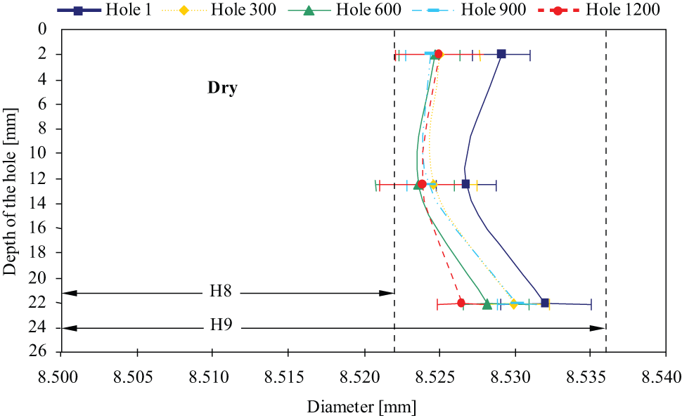
Dimensional behavior with the evolution of the number of holes for dry drilling.
The dimensional behavior as a function of the hole depth observed in the dry drilling, as can be seen in Figure 5, differs from the other conditions. A trend toward a concave shape can be observed, with larger diameters at the initial and final regions of the holes and smaller diameters in the central region.
This result differs from previous literature. In three studies previously cited in this article, the authors found bell-shaped holes under dry condition. Bono and Ni 13 conducted experiments in dry drilling of Al 319 with HSS drills, to produce holes with diameters of 9.92 mm and a depth of 25 mm. Haan et al. 30 also used HSS drills to drill holes with diameters of 4.5 mm and a depth of 25 mm in aluminum alloys. Brandão et al. 19 used similar tools to those applied in this study—carbide DIN 6537 K drills, 8.6 mm diameter—in drilling of AISI H13 steel.
Similar results were found by Kurt et al., who performed tests with HSS drills to machine Al 2024 alloy (holes with diameters of 10 mm and a depth of 30 mm). They also obtained bell-shaped holes, but an inverse bell-shape, that is, a larger diameter was obtained at the beginning of the holes than at the bottom. 1
A hypothesis suggested to explain the different results obtained in this article is based on the formation of micro-welding zones on the hole surface. Figure 6 presents the surface texture of the first and last holes machined by one of the tools tested for the dry condition. Each pair of (a) and (b) images represents the same region. The (a) images were obtained with a stereoscope, while the (b) images were registered using an optical microscope.
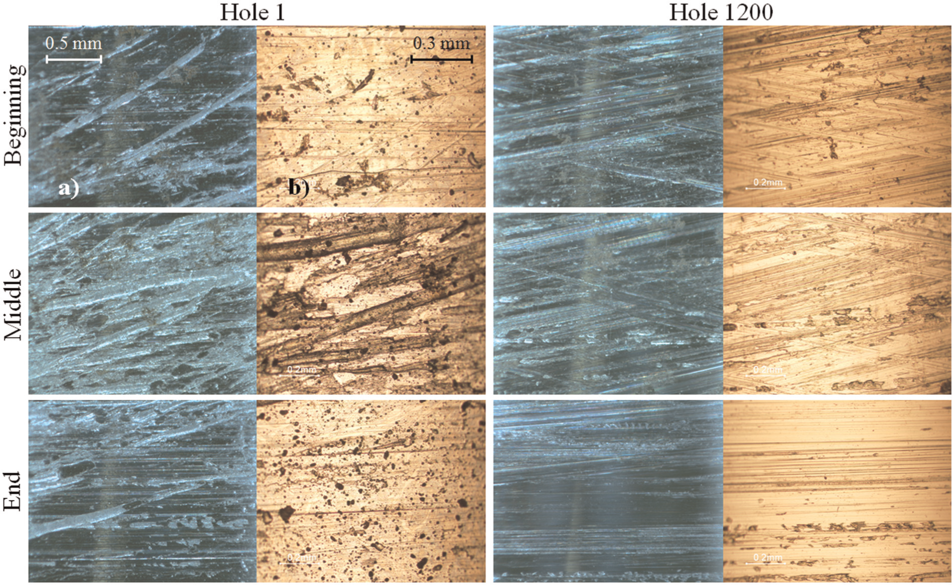
Surface texture of the first and the last hole for dry drilling conditions.
Analyzing Figure 6, it is possible to observe a greater quantity of adhered material in the central region of the holes, especially for the first hole. Since the differences between the diameters of the different hole regions are micro-meters in size, the formation of these micro-weldings can determine the diameter reduction observed in the central region of the holes. The occurrence of micro-welding is characterized by the welding of removed material particles on the surface, constituting a micro-layer of plastic deformed material, which reduces the diameter of the hole.
At the beginning of the first hole, some adhesions of removed material are observed on the surface and higher material adhesion is found in the central region (Figure 6, hole 1, middle), while in the final region, the surface presents a smooth aspect, due to the greater friction and heat generation in this region of the hole. This behavior results in the observed diameter variations, with the regions of lesser material adhesion presenting a larger diameter. The last hole presents a more homogenous texture along the hole, with less material adhesion in the central region (Figure 6, hole 1200, middle) in comparison to the first hole, this behavior being consistent with the smaller diameter variation observed between the different hole depths.
The presence of micro-welded material on the surface was also detected in other studies. Zeilmann et al. observed, during drilling of a AISI P20 mold steel with carbide tools and different cutting fluid applications (flood, MQL and dry), the presence of micro-welded material on the hole surface when dry drilling. According to the authors, the holes machined in dry condition presented the worst visual aspect, with evidence of material adhesion along the holes. The presence of the micro-welded material was confirmed by optical evaluation of the hole and the hardness by micro-indentation of the adhered material (846 HV), showing values twice as large as the bulk material hardness (390 HV). This behavior was related to the high thermal and mechanical loads submitted to the chip, which lead to a hardness increase. 32
In dry machining, increased friction and greater heat generation occur in the interface tool–workpiece–chip. 1 The heat distribution greatly influences the final quality of the holes. In their work, Bono and Ni 13 showed the effects of thermal distributions on the nominal diameter in drilling and concluded that dimensional variations in drilling suffer great influence of the heat generated in the process. As in the tests performed by those authors, the machining of AISI P20 steel carried out for this study also suffered effects on the dimensional and shape precision caused by the thermal distributions along the hole, despite the differences between the mechanical and thermal properties of the tools and materials used in the two studies.
Moreover, besides the effects of workpiece and tool expansion, the heat influences the generation of the hole surface, and irregularities on the surface may generate dimensional and shape deviations. In the results obtained with the dry condition, the major heat generation caused a higher plasticity of the removed material, which impedes its flow, and resulted in the welding of material particles to the surface, thus giving rise to the micro-welding. Figure 7 presents comparative graphs of the dimensional behavior observed for each fluid application condition, in the first and the last machined holes.
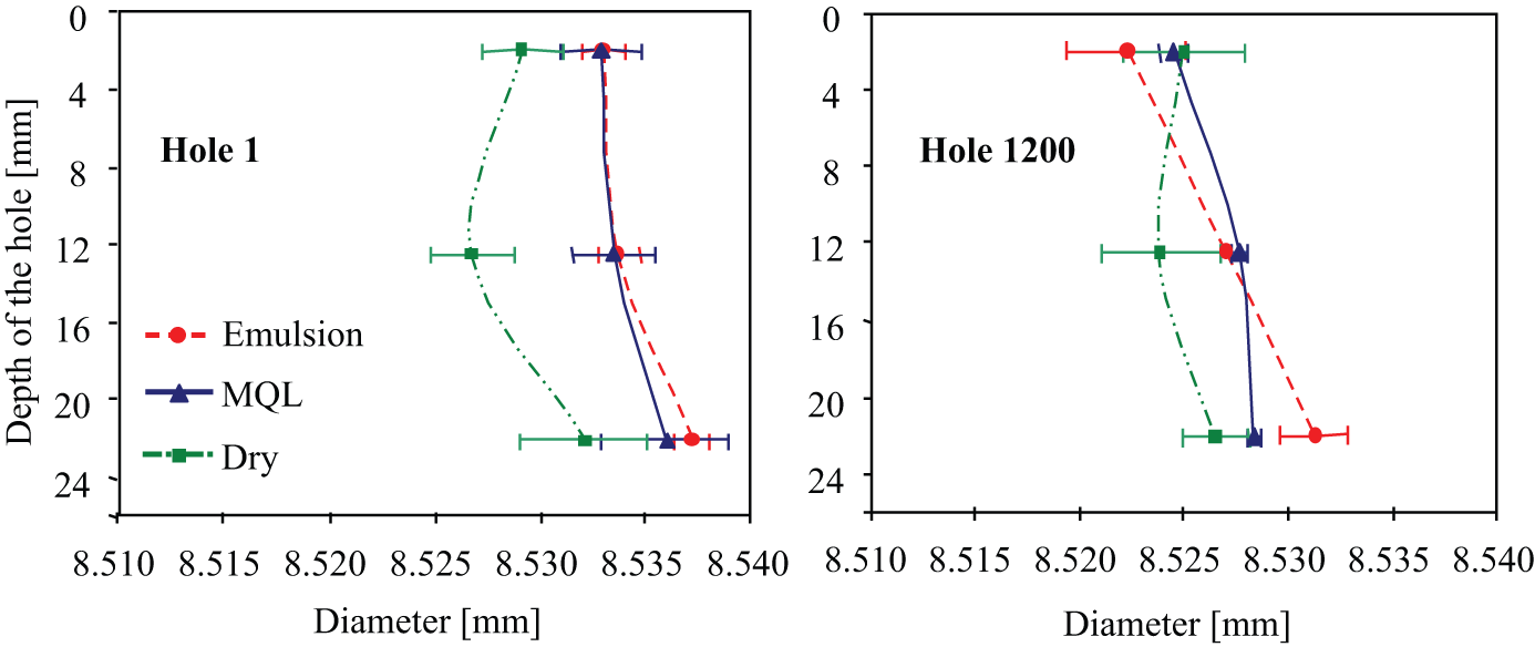
Comparison of the dimensional behavior between the different conditions of cutting fluid application.
Analyzing the measurements on the first hole, the condition which resulted in diameters closer to the nominal value was the dry condition, followed equally by the conditions of emulsion and MQL. They also presented similarity in their hole shapes (bell shape), whereas the dry condition presented a concave shape. As for the last hole, a trend toward smaller diameters in the dry condition is observed. However, considering the statistical dispersion, there is no significant change between the three conditions.
Circularity
The circularity error consists of a shape error, that is, deviation of a geometric element in relation to its theoretical shape (in the case of circularity, the circle). These errors are caused mainly by the lack of rigidity (inadequate workpiece fixations and machine tool conditions), tool wear and temperature variations. In drilling, circularity errors occur when the diameter of the hole is not uniform along its depth. The hole acquires a bell-shape, cambered, concave or with inclined axis. The intensity of the error depends on the diameter and the relation length/diameter (l/d) of the tool. As means of minimizing the circularity error, the feed rate is increased and more rigid tools are employed. 2
The circularity of a hole presents, among the different parameters of dimensional control, an important role in the control of manufacturing process. This importance is defined by the functional characteristics of the hole, and for the cases where these characteristics present greater relevance and the deviations are evaluated by a preestablished margin of error. 33 The admissible circularity margin of error preestablished in this work was 22 µm. In all analyzed holes, the circularity was measured at three different depths (2, 12.5 and 22 mm), using the same procedure applied to evaluate the diameter. Figure 8 presents the circularity errors at three different depths with the increase in the number of machined holes under the application of emulsion. The result for 1200 holes does not have an error bar, since only one of the tested tools reached this number of holes.
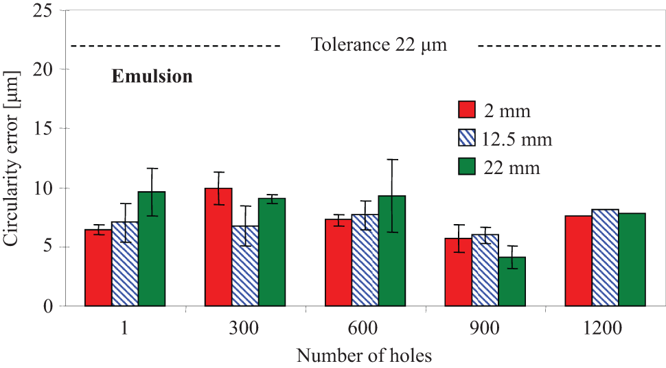
Graph of the circularity error with the evolution of the number of holes for drilling with emulsion.
The average circularity errors observed for drilling with the application of emulsion did not surpass the preestablished tolerance, and the values are around 50% less than the established limit. The analysis of the results also shows that there is no clear trend with the increase in the number of holes or with the depth increase. The observed variations are not significant, considering the statistical dispersion. Figures 9 and 10 present the circularity errors at three different depths with the increase in the number of machined holes, for the conditions with MQL and dry drilling.
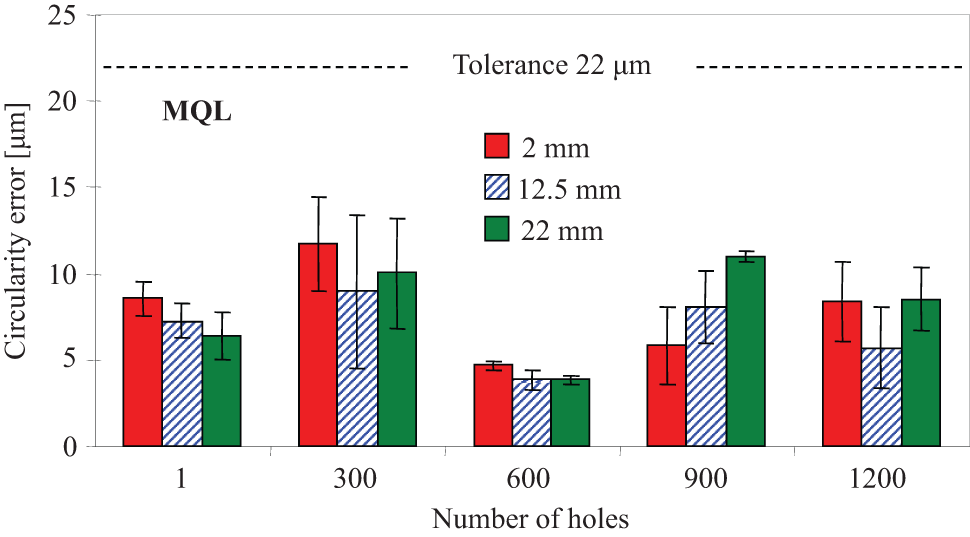
Graph of circularity error with the evolution of the number of holes for drilling with MQL.
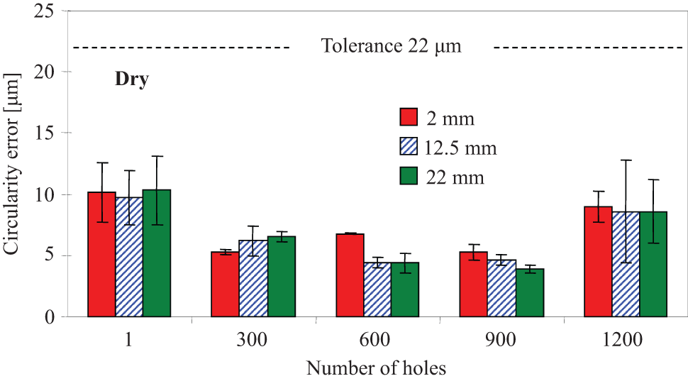
Graph of circularity error with the evolution of the number of holes for dry drilling.
The results obtained for the condition with MQL and dry also remained below the preestablished limit, and it is not possible to find a clear trend for the results. For both conditions, the circularity variation along the depth for the number of holes considered is not significant. With respect to the increase in the number of holes, a greater variation in results compared to the other conditions is observed for the MQL condition, however without any observable trend. For the dry condition, a small trend of greater errors in the first and last holes is observed. The greater values of circularity in the last hole may be related to the tool wear. To Bossardi et al., 29 the tool wear is the most important factor responsible for the circularity errors, due to the reduction of the cutting stability.
However, comparing the circularity errors of the first and the last machined hole in the dry condition, there is no significant change. Similar results were obtained by Neves et al., 31 in a study conducted on the drilling of AISI H13 steel with drills similar to those used in this study.
In Figure 11, a comparison is presented between the circularity errors of the last hole machined in each condition of fluid application. It is noteworthy again that the emulsion results do not present an error bar, because only one of the tested tools reached 1200 holes.
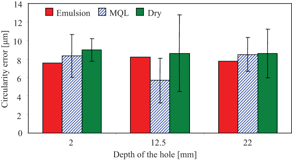
Comparison of the circularity errors at the different depths of the last machined hole in each condition of fluid application.
It is observed that, considering the statistical dispersion, it is not possible to establish differences between the different conditions for any of the three analyzed hole depths. Only in the central region of the hole, a trend of higher values for the dry condition is verified, due to the bigger error dispersion. This behavior may be related to the occurrence of micro-welding at the hole surface. As observed in the texture analyses, micro-welding occurred especially in the central region of the holes.
Zeilmann, in drilling of a titanium alloy (Ti6Al4V) with MQL external application, detected the presence of micro-welded material on the surface through the circularity analysis of the machined hole. In his work, the author observed that in regions with the presence of micro-welded material, the peaks of circularity deviation were higher. Even though the global machining conditions differ from those used in this study, the cited results present aspects that assist in understanding the great circularity variations, observed for the dry condition. 33
Similar comparisons made by some authors using HSS twist drills presented greater circularity errors in the dry condition, due to the greater severity of the process. 34 This behavior was not observed clearly in this study, and this fact may be related to the strategy used in the dry condition, of intermittent drilling with retreat of the tool, which provides a better dissipation of the heat generated in the process.
Performing a global evaluation of the circularity results, it is verified that none of the conducted analyses showed clear trends. This fact may be associated with the large number of variables involved. As none of the variables presented a preponderant effect over the others, a balance of effects occurred, tending to generate similar results, without significant variations.
Conclusion
The machined holes in the three tested conditions of fluid application presented dimensions greater than the nominal diameter. The largest diameters were obtained in the conditions of emulsion and MQL, and the results of both conditions were lower than the tolerance H9. In the dry condition, the analyzed holes showed smaller diameters when compared to the other conditions. The reduction of the diameter with the evolution of the number of machined holes was observed for all tested conditions, due to the progressive wear of the tool edges.
Considering the different evaluated depths, holes obtained with application of emulsion and MQL presented greater values for the diameter in the final region, resulting in a bell-shape behavior. The holes drilled in dry condition presented a concave shape, with smaller diameters in the central region of the holes, related to the formation of micro-welding on the holes surfaces.
The circularity errors did not present significant variation when comparing the different analyzed depths of a same hole. However, greater dispersion of errors was observed for the center region, on the dry drilling condition, related to the characterized micro-welded material. The comparison between the conditions of fluid application performed for the last hole also did not present significant variation. Regarding the increase in the number of holes for each tested condition, some variation on the results was observed for the dry condition, though without any clear trends.
Footnotes
Declaration of conflicting interests
The authors declare that there is no conflict of interest.
Funding
The authors thank the University of Caxias do Sul for the support to the project Dry Drilling of the Machining Group (GUS) and to the partner companies Walter AG Company and Blaser Swisslube of Brazil Ltda.