
Abstract
A tryout process is a series of procedures to obtain robust stamping by a trial stamping before transferring to a press shop. During the tryout, control of the drawbead, determination of the blank shape, modification of the binder surface, and so on are carried out mainly using a trial-and-error approach. As the level of difficulty increases, the formability involved in the stamping becomes sensitive to the contour of the deformed shape, or the blank shape. In order to solve the formability problems involved in the stamping of parts that are very difficult to form, a digital tryout that simulates the real tryout process in conjunction with a beadless stamping is demonstrated. Furthermore, the possibility of practical applications is investigated by showing a solution procedure for the proposed digital tryout. Since the digital tryout is carried out on the desktop rather than in the press shop, precise control of the deformed contour can be realized if the optimal blank design technique is used in the determination of the blank shape. The validity and advantages of the digital tryout method are confirmed with examples of auto parts that are very difficult to find robust stamping condition.
Introduction
Urgent issues in sheet metal forming that are mainly related to the automotive industries include weight reduction, cost reduction, a shorter development period, and functional integration of parts. As the integration of functions progresses, the shape of a part becomes complicated, which aggravates concentrated straining. This localized straining and the increased use of high-strength steel increase difficulties in stamping process development. The demand for a shorter development period is closely related to the shortening of the tryout period.
If the shape of a part and its materials are specified, the remaining parameters of the stamping process are the shape of binder surface and the process conditions (e.g. the drawbead, blank shape, and blank holding forces). Since metal flow is mainly controlled by the remaining parameters in a conventional stamping process, these parameters (especially process conditions) should be carefully adjusted during the tryout process. Both the drawbead shape and the blank shape are determined simultaneously after going through the tryout stage. Because both parameters significantly affect the metal flow, the difficulty of the tryout is dramatically increased due to the increased number of parameters to be adjusted. Moreover, if the metal flow during stamping is complicated and the stronger blank material is used, namely if hard-to-form parts are to be stamped, the difficulty of stamping is far more aggravated. In order to avoid fracture for hard-to-form parts, both the drawbead shape and blank shape should be carefully adjusted on a position-by-position basis over the entire region. The number of trial-and-error attempts during the tryout is increased until a robust stamping process condition is found.
A tryout process is a series of modifications of stamping dies in order to find a robust stamping condition using trial stampings before transferring the stamping dies to the press shop. Through the tryout process, determination of the blank shape, tuning the drawbeads, and modification of the binder surface (if necessary) are carried out. After the trial stamping with a test blank shape, the deformed shape is carefully checked to determine whether fracture or wrinkling has occurred. If defects have been found, modification of the blank shape, and/or the drawbead, is iteratively carried out until the deformed shape shows no defects. Despite these efforts, if defects do not disappear completely, the modification work includes the binder surface as the last resort. If process conditions have been determined properly over the entire range, the possibility of robust stamping is increased.
Based on observations and discussions with tryout engineers, blank shape modification work seems to be conducted with respect to the target deformed contour. If fracture is found in a certain region during tryout, an appropriate measure to fix the problem would be to increase the metal flow to the region. In order to increase the metal flow, either retraction of the target deformed contour near the region or removal of the drawbead is selected in the real tryout. On the contrary, if wrinkling is found, then the expansion of the target deformed contour can be selected. Recently, a “beadless stamping” process1,2 has been proposed by the present author, wherein metal flow is controlled by the desired deformed contour (i.e. the target shape) with minimal aid from the drawbead. Metal flow is typically controlled by the restraining force provided either by the blank holder or by the drawbeads; hence, the effect of the blank shape has usually been neglected or independently considered. Although the well-known works by Nine3,4 and Wang 5 have contributed to the development of sheet metal forming significantly, they emphasize the drawbead, and the effects of the blank shape have not been sufficiently considered until now. The spectrum of the academic works related to the drawbead covers analytical and numerical modeling of the drawbead to predict the restraining force, experimental works with a drawbead simulator, 6 an active drawbead, 7 and a variable blank holding force with a segmented blank holder. 8 In contrast to academic works, experienced stamping engineers are already aware of the effect of the blank shape on material flow and they usefully exploit this effect during the tryout stage.
Parts with complicated shapes made of high-strength steel often cause formability-related problems. In this case, the success of the stamping process is highly sensitive to the contour of the deformed shape. Therefore, the deformed contour should be carefully controlled, especially if the part is difficult to form. Since the deformed shape is determined with the blank shape in the stamping, the corresponding blank shape should be determined as accurately as possible. However, determination of a blank shape that deforms into the desired shape with a given stamping process is another task.
Digital tryout
An optimal blank refers to an initial blank shape that deforms into a desired shape through a stamping process. The optimal blank not only improves formability and product quality, but also reduces material costs, the number of trials in the tryout stage, and consequently the length of the product development period. In the beadless stamping process, metal flow is controlled by the desired deformed contour (i.e. the target shape) with minimal aid from the drawbead. Because the target shape is the shape after deformation, the desired deformed shape cannot be controlled directly. The blank shape that deforms into the desired shape can be found using the optimal blank design method. Therefore, the optimal blank design is a core tool in beadless stamping with respect to deformed contour control. The radius vector method 9 has been selected in the beadless stamping process as the design tool since both the accuracy and convergence of the method have been verified, even for complicated shapes such as automotive parts.
Because metal flow is mainly controlled by the target shape in beadless stamping, and hence the corresponding blank shape, both the accuracy and convergence of the optimal blank design are critical. Moreover, the digital tryout is a trial-and-error process. As with the real tryout, the possibility of a better solution is increased if more trials are made within the allowed development period. By taking advantage of beadless stamping, a greater number of problems related to the formability of hard-to-form parts can be solved at the desktop. Therefore, the real tryout process can be more easily conducted by providing virtually derived optimal process conditions that are closer to the actual final plan to the tryout engineers.
Using an application to an actual automotive part, the beadless stamping process has been verified as highly effective in terms of formability improvement and material usage. 1 However, a demonstration of practicality is still needed with different kinds of examples.
Figure 1 shows a flow chart of a beadless stamping digital tryout process. With information regarding the die shape (wherein the drawbead is removed) and with a trial blank shape that is expected to deform to a desired contour, analysis of the deformation process can be performed using any kind of stamping process analysis software. The results of the analysis are investigated using the forming limit diagram (FLD) function to determine whether tearing or wrinkling (i.e. a defect) has occurred. If a defect is found, the target shape is modified. With the modified target shape, another trial blank shape is determined using the optimal blank design method, and the deformation analysis is repeated until no defects are found in any of the parts.
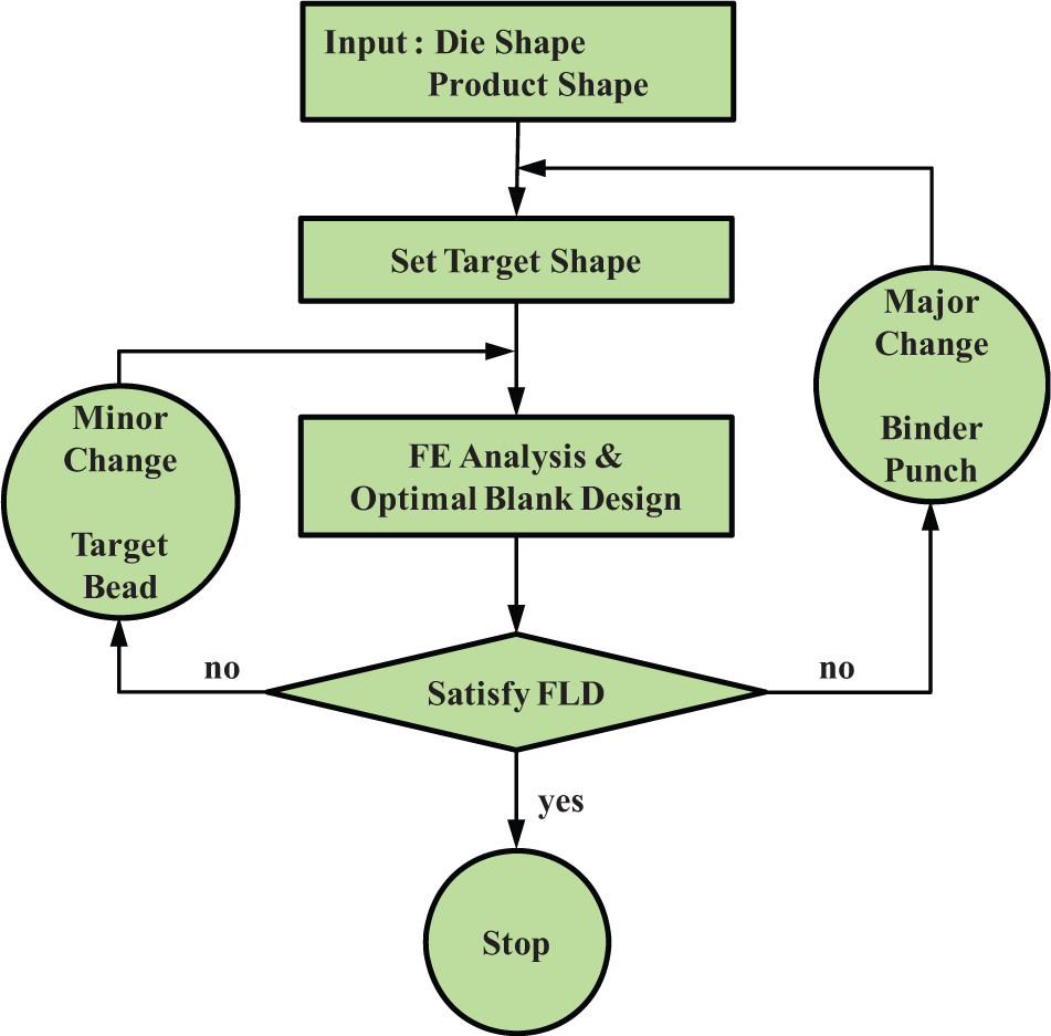
Flow chart of digital tryout.
There are three iteration loops in the proposed digital tryout technique. The innermost loop is the optimal blank design loop, which is used to find an accurate shape for the trial blank that deforms into the target shape. The next loop is used for the determination of the target shape and bead position, which is the core of the digital tryout. The last resort loop of the digital tryout is used to modify the binder shape or part shape.
Since the digital tryout emulates a real tryout, the quality of the plan significantly depends on the trial target shape. Therefore, the number of trials can be greatly reduced if the experience of the engineers is used in the selection of the bead position and the determination of the target shape.
As compared with a real tryout, a digital tryout has the following advantages:
A process plan of better quality is expected. Since modification of the work is conveniently conducted at the desktop, a greater number of trial-and-error experiments can be evaluated than in a real tryout.
A relatively easy tryout process. The number of parameters to be adjusted is reduced because the metal flow is controlled by the target shape, that is, by a blank shape only.
Improved formability, since the role of the drawbead is limited to prevent rigid body motion, and to not to retard metal flow.
Less use of blank material, contrary to common sense (the drawbead may result in a reduction of blank size). 10 Since the drawbead lines are typically used as the reference for the deformed shape, stamping dies with drawbead lines require a larger blank size. The effect of stretching due to the drawbead restraining force cannot be compared with the effect of a reduction in the desired deformed shape.
A re-evaluation of conventional stamping as a substitution for hot stamping. The hot stamping process is widely used for the stampings of hard-to-form parts. Compared to conventional stamping, the hot stamping process requires significant investment to build a production line and has high energy consumption.
The possibility of integrated consideration of the stamping process. Most of the blank shapes used in the conventional stamping process are rectangular or polygonal, which can be produced by a shearing process. However, the derived blank shapes from beadless stamping mostly consist of curved lines, which need to be produced by a blanking process. Even if the blank shape is determined through a digital tryout, the blank shape still has a further possibility of modification since the production cost of the blank, including the cost of the blanking die, should be considered for the integrated optimization of the stamping process.
Examples of process improvement
The proposed concept for digital tryout using beadless stamping was verified with a real auto part through comparison with the original process plan before tryout. DYNAFORM™ commercial stamping analysis software (Version 5.7.3, Engineering Technology Associates Inc., Troy, MI, USA) was used in this study. The initial blank shape used to initialize the digital tryout was found from a predetermined trial target shape using the blank size estimation (BSE) function in DYNAFORM. Initially, with the obtained blank shape, the deformation process was analyzed. The shape error between the deformed shape and the target shape was measured at every node on the contour. If the shape error exceeded the specified allowance, the blank shape was modified based on the magnitude of the shape error until the error reached the specified allowance. A more detailed explanation of the radius vector method is given in Shim. 9
Example 1
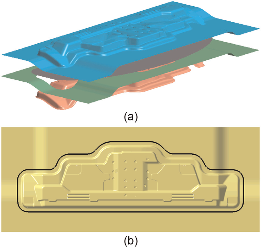
Figure 2(a) shows the die geometry of example 1. The main characteristics of this stamping die are a binder surface with two steps, and a doubly bent nearly vertical wall located at the straight edges. Because of the characteristics of this shape, a strong possibility of fracture was expected, especially at the front straight edge. In the original design, the blank shape is rectangular (SGC340, 0.7 mm, 920 mm × 260 mm) and the four separated straight drawbeads (in the top view) are installed along the punch opening line, as shown in Figure 2(b). Properties of the blank material, SGC340, which is shown in Table 1, are selected from the material library of DYNAFORM.
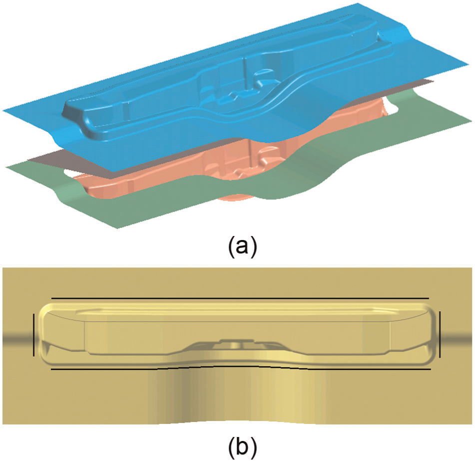
Original stamping die (example 1): (a) drawing die set and (b) top view to show drawbead line.
Material properties of SGC340.
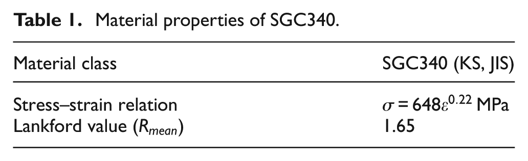
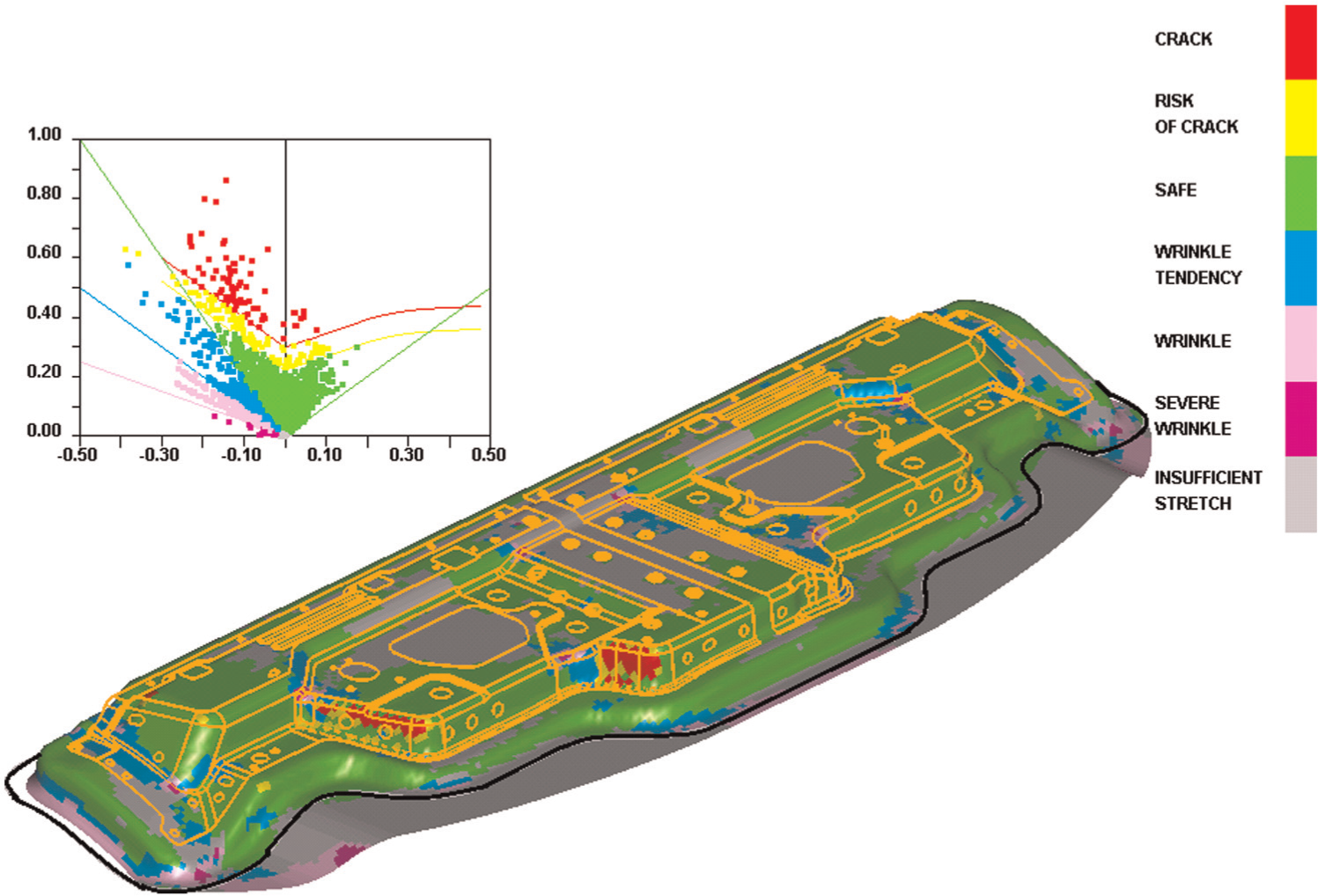
Figure 3 shows the FLD of the original design, determined using DYNAFORM, where severe fracture was expected to occur near the straight vertical wall. The severe fracture is due to the excessively large blank size and the drawbead, both of which impede metal flow.
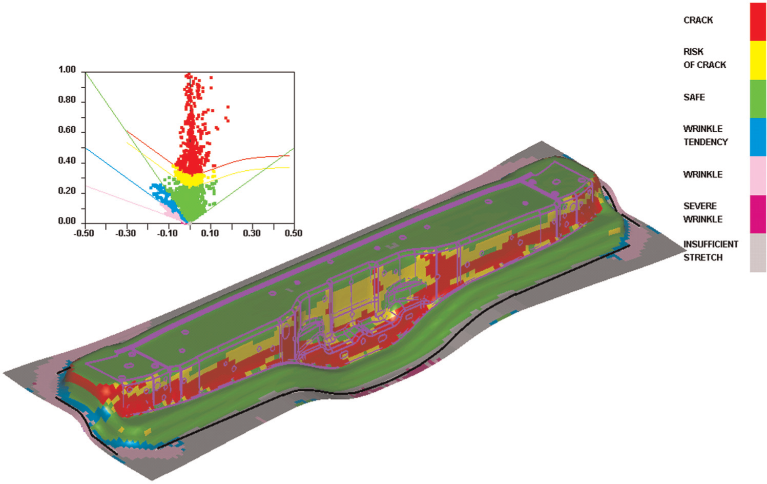
Forming limit diagram of original design.
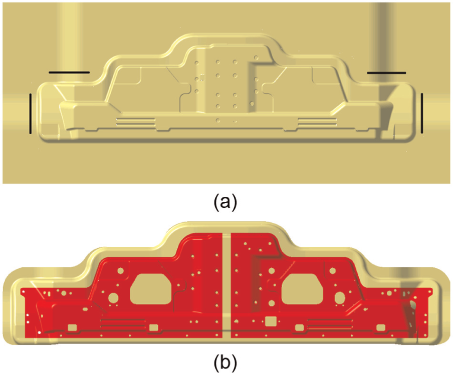
Compared to the length, the shape of the part is narrow in width and deep in height. If the drawbead is removed completely, then the contour of the deformed shape will be moved sensitively with respect to the change in the blank’s shape, especially along the width direction. 1 This makes the tryout difficult. Therefore, a short line of drawbead was installed on one side of the straight edge in order to restrict the blank from moving freely, especially along the width direction, as shown in Figure 4(a). Figure 4(b) compares the desired deformed shape and the part shape. The determination process for the drawbead line in Figure 4(a) and the target shape in Figure 4(b) is the digital tryout itself, since both are determined by the examination of analysis results through the second loop of the digital tryout.
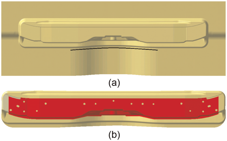
Modified design for beadless stamping: (a) drawbead line and (b) comparison of product shape and target shape.
The blank shape to be deformed into the desired shape (i.e. the optimal blank) was evaluated until the maximum shape error became less than 7.0 mm at every node on the contour. The magnitude of the allowable shape error can be decided by the engineers by considering the degree of improvement from the digital tryout, the deformation behavior characteristics of the part, and the allowable development period.
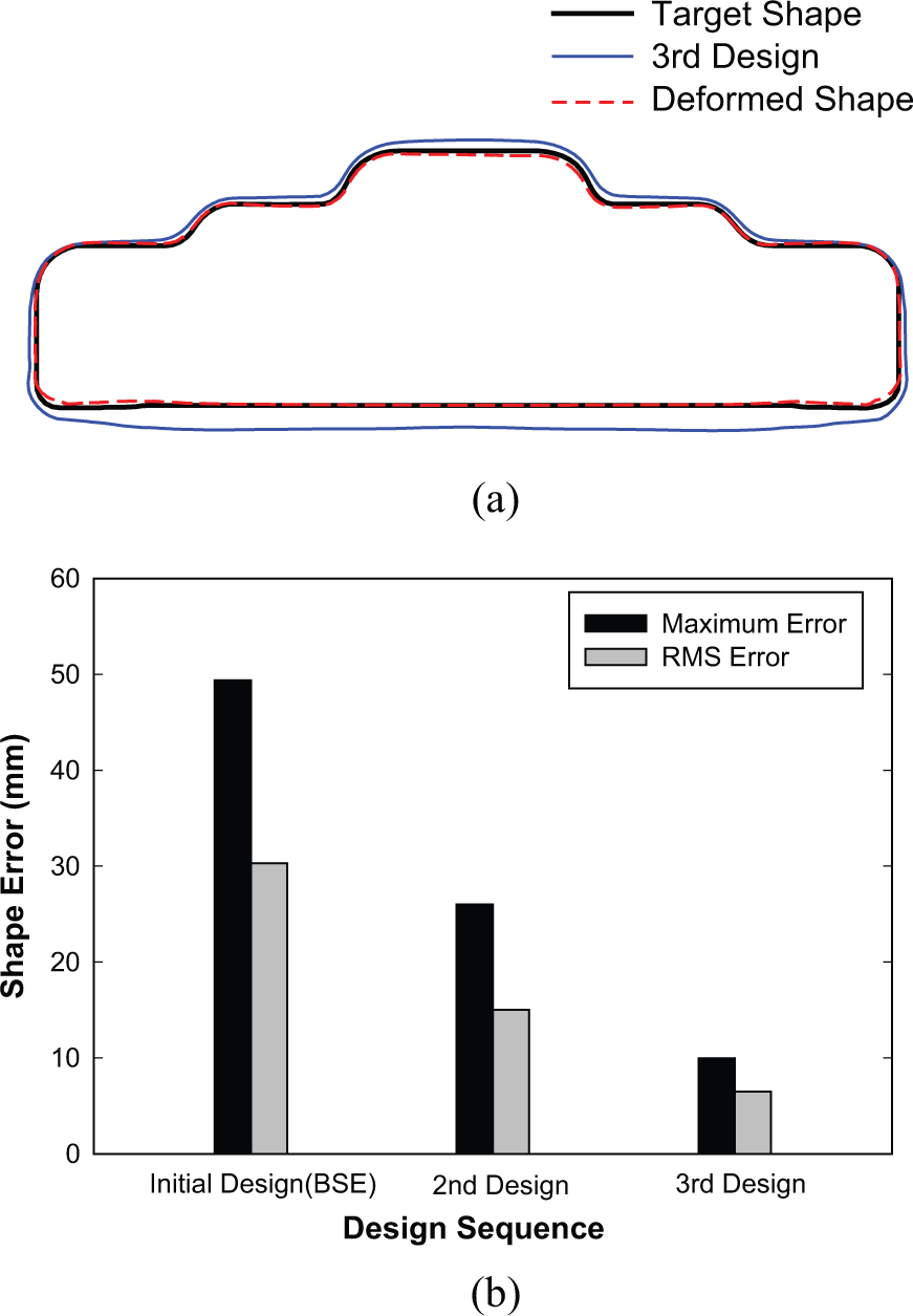
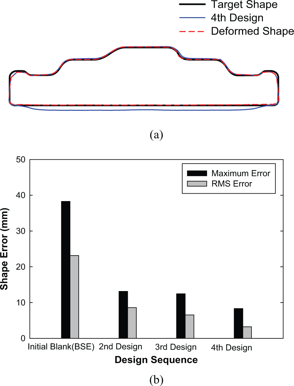
Figure 5(b) shows the optimal blank shape at the fourth design stage and the corresponding deformed shape, in comparison to the target shape. The optimal blank shape was determined using the radius vector method, starting from the blank shape of Figure 5(a), which has been determined using the BSE function of DYNAFORM. The shape error reached the shape error allowance at every boundary node after the third modification, resulting in four cycles of deformation analysis. Figure 5(c) shows a change in the shape error during the evolution of the optimal blank design. Since the shape error is measured at every node on the contour, the shape errors are different from node to node. “Max. error” refers to a maximum value among all the shape errors. “Root-mean-square (RMS) error” refers to the RMS value of the shape errors. At the fourth design stage, the maximum error became less than 7 mm and the RMS error was about 3 mm. This implies that the deformed shape almost coincides with the target shape, except at some points.
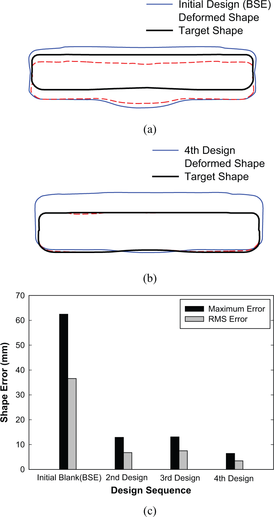
Evolution of optimal blank design stage: (a) initial design (BSE), (b) fourth design, and (c) change of shape error.
As the level of difficulty in the stamping increases, the FLD becomes sensitive to the deformed shape, especially with respect to the contour of the final shape. Since the optimal blank is the blank shape that deforms into the desired shape, the success of the digital tryout is significantly dependent on both the accuracy and convergence of the optimal blank design. If the accuracy of blank shape prediction matters, then target shape control, which is the main idea of the digital tryout, is not possible. If convergence matters, the number of employable trials to examine the plan of the target shape during the tryout stage will be reduced, since a sufficient development period is typically not given to the engineers. As shown in Figure 5(b), the shape error decreases rapidly, and the accuracy and the convergence of the chosen optimal blank design method are thus verified as being an adequate tool for the digital tryout.
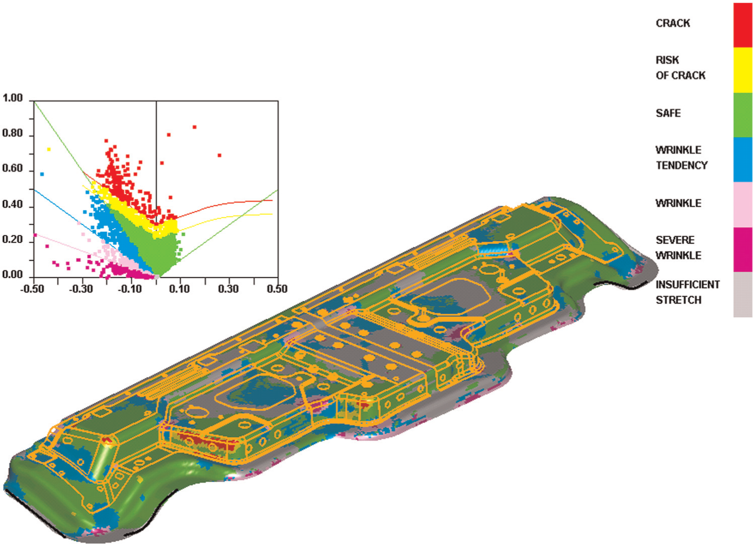
Figure 6 shows the FLD with the optimal blank. Comparing this diagram to Figure 3 (the original design), the results of the digital tryout reveal a dramatic improvement. Figure 7 shows the optimal layout of the optimal blank to obtain the optimal sheet metal usage, where the minimum required area per blank was found to be 883 mm × 219 mm (i.e. 19.1% less blank area than used in the original plan). Despite the fact that the derived blank shape from the digital tryout is close to a rectangular shape, the blanking process is inevitably required to produce the blank since the contour of the blank contains a curved line.
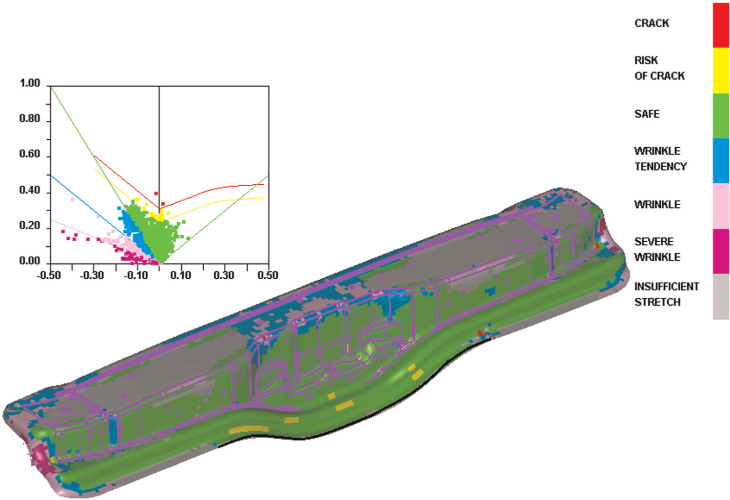
Forming limit diagram (optimal blank).
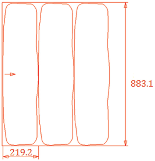
Optimal nesting of optimal blank shape.
Irrespective of the evident advantages of digital tryout (reduction of blank usage and improved formability), engineers tend to prefer a shearing process rather than a blanking process because the following problems are expected if a blanking process is used: increased production cost (blanking die, added process), a shortened development period, modification of the production line layout, mental pressure on the engineers due to the double contouring processes (blanking and trimming), and doubled key processes (blanking and drawing).
In order to mitigate these issues, the derived optimal blank shape is further modified into a rectangular shape (882 mm × 207 mm), as shown in Figure 8. This shape can be produced using a simple shearing process based on the observation that the derived shape is not far from rectangular. When modifying the blank shape, the results of both simulation and the final product shape were considered, as shown in Figure 6.
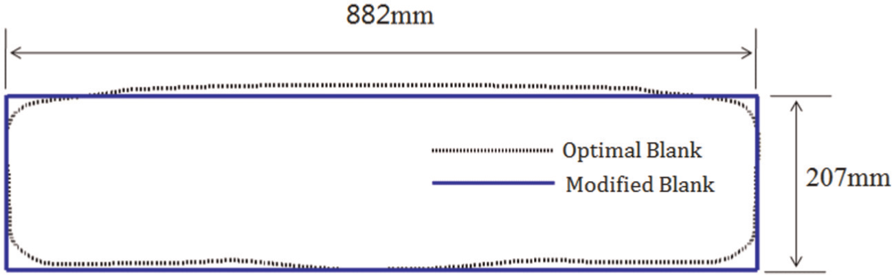
Further modification of blank shape from optimal blank.
Figure 9 shows a FLD with the modified rectangular blank. By comparing this diagram to Figure 6 (the optimal blank), the results show a dramatic improvement of formability and a reduction of blank material. The reason why the modified blank shows better results than the optimal blank is that the blank area corresponding to the area to be trimmed off was further considered. Due to additional modification, the formability and the usage of blank material have been improved compared to the optimal blank.
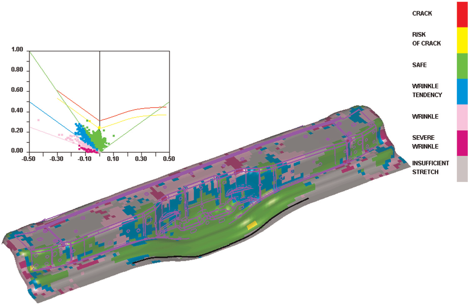
Forming limit diagram (modified blank).
It should be noted that despite the determination of the blank shape, stamping cannot be successful if the blank is not positioned at exactly the correct location. Therefore, for successful stamping, both the blank shape and the location should be carefully controlled.
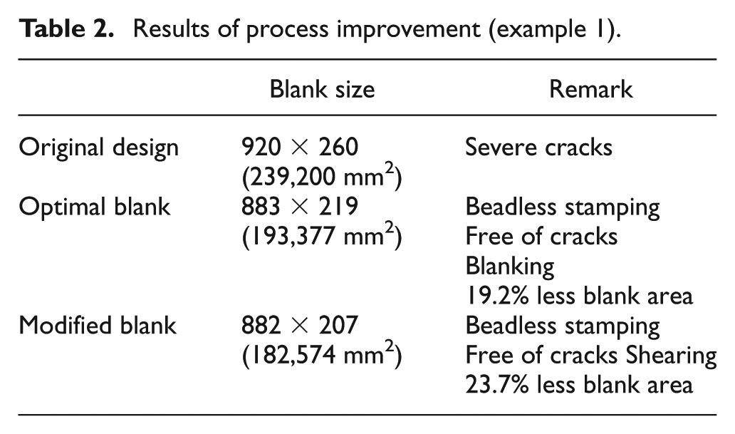
The results of a digital tryout are summarized in Table 2. In the original design, the stampings of a rectangular blank at the stamping die with the surrounding drawbead show severe cracks. The optimal blank, derived from beadless stamping, does not show a crack, and 19.2% less blank material is required compared to the original design. However, in order to produce the optimal blank, the blanking process is needed because of the curved contour of the blank. The optimal blank shape is further modified into a rectangular shape, which enables the shearing process. The modified blank shows no cracks, and 23.7% less blank material is required compared to the original design. Consequently, the author verified that beadless stamping, which was realized using the proposed digital tryout technique, provided great improvement in terms of formability and reduced use of blank material.
Results of process improvement (example 1).
Example 2
Figure 10(a) shows an isometric view of the original stamping die. The main characteristics of this example are that both the reentrant corners and protruding vertices coexist in the top region, the punch opening line is highly complex in the front region, and triple bending (bending-reverse bending-bending) is induced during the drawing process due to the designed step at the bottom of the front (nearly vertical) wall of the punch. Because of the characteristics of the part’s shape, both wrinkling and fracture can occur simultaneously at the specific region due to the highly complicated deformation mode, and the success of the stamping is extremely sensitive to the shape of the blank. In the original design, the blank shape is close to a half-circle (SGC340, 0.6 mm, 1130 mm × 385 mm), and the drawbead was installed 15 mm from the punch opening line, as shown in Figure 10(b). Figure 11 shows the FLD of the original design, where severe fracture was expected to occur near the side edges of the front face.
Original stamping die (example 2): (a) drawing die set and (b) top view to show drawbead line.
Forming limit diagram (original design).
In order to solve this fracture problem, the proposed digital tryout in combination with beadless stamping was applied. After the drawbead surrounding the punch opening line was removed completely, four short drawbeads were reinstalled at the front and side of the part in order to restrict the blank from moving freely, as shown in Figure 12(a), while the front center region and rear region can deform freely in order to supply blank material to the regions where fracture has occurred. Figure 12(b) compares the desired formed shape (i.e. the target shape) and the part shape. From the deformed shape, the part is obtained with the trimming process. The target shape shown in the figure was determined by examination of deformation analysis results through trial and error, which is the left loop of the digital tryout process shown in Figure 1.
First modification (drawbead, target shape): (a) drawbead line and (b) product shape and target shape.
The optimal blank design processes are conducted to obtain the initial blank shape until the maximum shape error becomes less than 10 mm at every node on the contour. Figure 13(a) shows the determined optimal blank by comparing the undeformed shape, target shape, and deformed shape, after three innermost iteration loops starting from the BSE. Figure 13(b) shows the change of the shape error during the evolution of the optimal blank design.
Optimal blank design (first modification): (a) product shape and target shape and (b) change of shape error.
Figure 14 shows the FLD of the optimal blank. Comparing this diagram to Figure 11 (the original design), the results do not show significant improvement, but the wrinkling tendency has been aggravated. The reason why noticeable improvement was not made is ascribed to the target shape. Since the target shape shown in Figure 12(b) is determined by locating the drawbead, as shown in Figure 12(a), as close as possible to the punch opening line, it seemed impossible to design a new target shape that is smaller and better than the present target shape. In order to overcome this problem, major changes, including the binder shape, were considered.
Forming limit diagram (first modification).
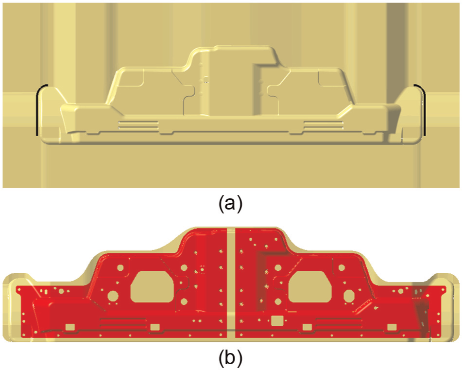
Figure 15 shows the changes in binder shape by comparing the new design with the original design. In the original design, as shown in Figure 15(a), the clamping depth required to finish the binding action is 84.5 mm, and three types of bending occurred during the binding action. The clamping depth was modified to 76.0 mm, and single bending occurred in the modified design as shown in Figure 15(b).
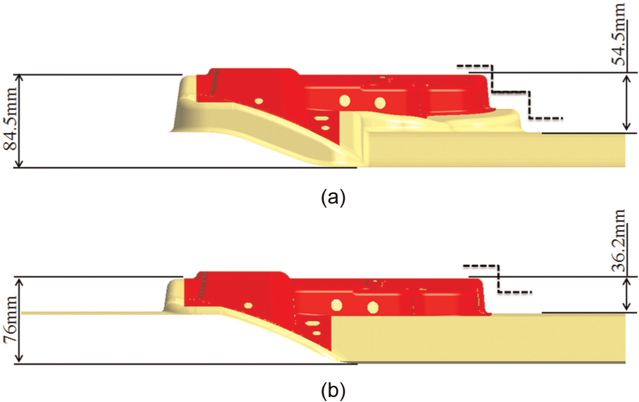
Change of binder surface (second modification): (a) original design and (b) modified design.
Figure 16 shows the FLD of the second modification, where the results reveal considerable improvement. However, some possibility of fracture still exists.
Forming limit diagram (second modification).
In order to solve this problem, modification of the fillet radii in the region of the product, whose changes are strictly prohibited in the stamping die, in general, is inevitably considered in the third design. As shown in Figure 17, the fillet radius of the upper edge of the vertical wall was changed to R15 in the third design. From R5 in the original design, the radius of the lower edge of the vertical wall was changed to R8 from R3. In addition to this fillet radius change, the target shape and the drawbead line were also changed in order to increase metal flow, especially near the vertical wall, as shown in Figure 18.
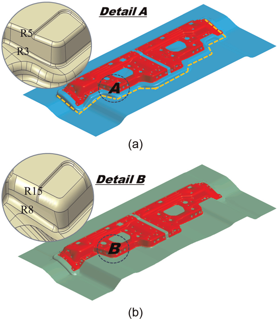
Third modification (fillet radius): (a) original design and (b) modified design.
Third modification (drawbead, target shape): (a) drawbead line and (b) product shape and target shape.
Figure 19(a) shows the determined optimal blank by comparing the undeformed shape, target shape, and deformed shape after four cycles of optimal blank design starting from the BSE. Figure 19(b) shows the change in shape error during the evolution of the optimal blank design.
Optimal blank design (third modification): (a) optimal blank and (b) change of shape error.
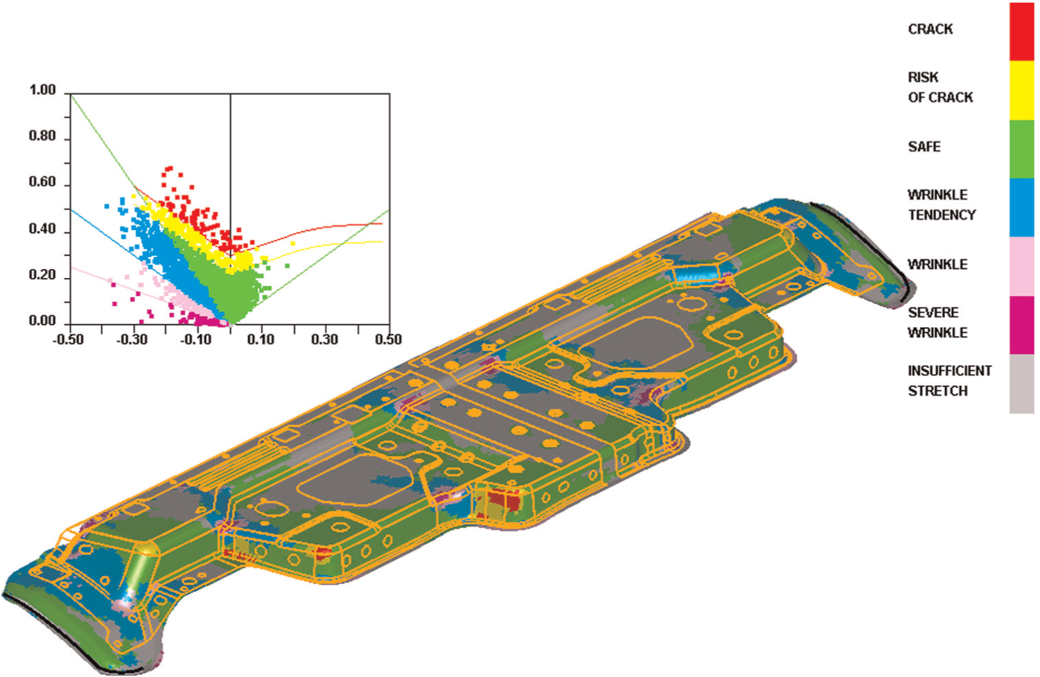
Figure 20 shows the FLD of the third modification, where a successful stamping condition was obtained eventually, since most dots were located at positions lower than the forming limit curve. Although some dots located above the forming limit curve still existed, the results show a great improvement compared to the second modification, as shown in Figure 16.
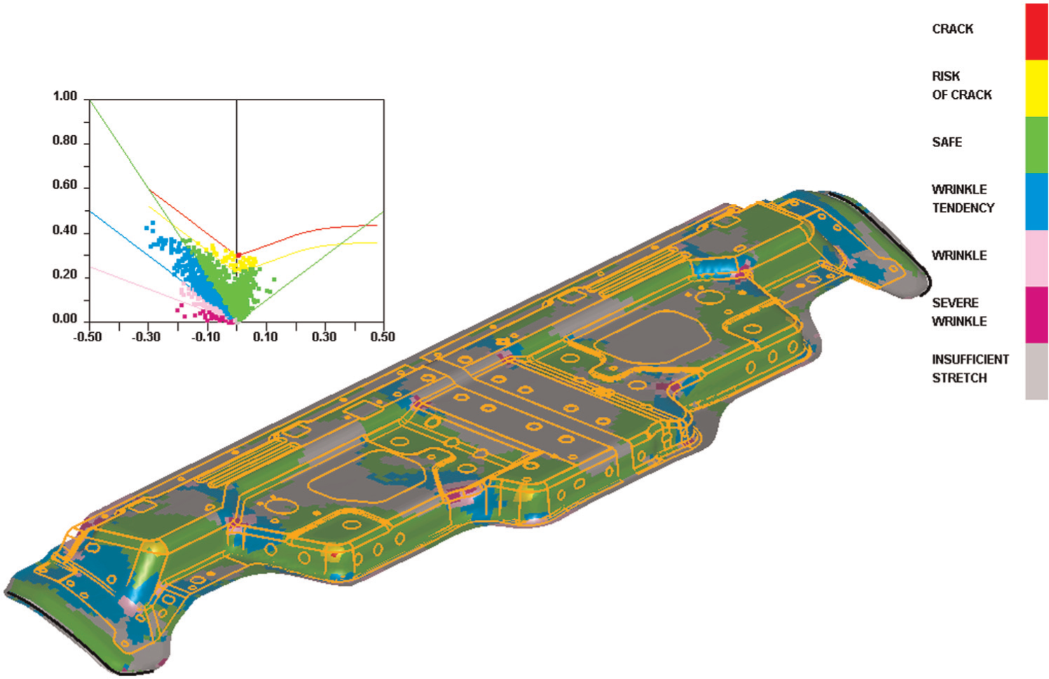
Forming limit diagram (third modification).
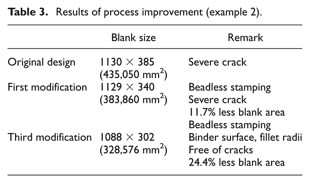
The results of process improvement due to digital tryout are summarized in Table 3. In the original design, severe cracks occurred due to the drawbeads. In the first modification, only minor changes (e.g. the target shape and drawbead as the position stabilizer) were imposed. However, the results showed a strong possibility of cracks. After major changes (e.g. modification of the binder surface and the fillet radii), the possibility of cracks was almost eliminated and successful stamping conditions were obtained. Using the proposed digital tryout, including the major change, the usage of blank material was reduced by 24.4% compared to the original design.
Results of process improvement (example 2).
Conclusion
The author verified the practicality of the proposed digital tryout in conjunction with beadless stamping through real auto parts examples that were extremely hard to form using conventional stamping. As the level of difficulty increased, the formability involved in the stamping became highly sensitive to the contour of the deformed shape. The proposed digital tryout was applied in order to overcome the difficulties with hard-to-form parts by inducing natural metal flow over the entire region.
Since the digital tryout was conducted with respect to the target deformed shape (which emulates the real tryout process), the target shape (and hence the blank shape) was iteratively adjusted according to the results of deformation analysis until successful stamping conditions were found. Since the proposed digital tryout is conducted conveniently on the desktop with an appropriate selection of an optimal blank design tool, a higher possibility of a better solution is expected versus the real tryout. Using our examples, the proposed digital tryout was shown to provide a dramatic reduction in the use of blank material and shortened the process development cycle due to increased formability. Moreover, the possibility of conventional stamping as a substitute for hot stamping, which requires considerable investment and high energy consumption, was validated since today’s hot stamping process is widely (and even blindly) used to stamp hard-to-form parts.
Footnotes
Declaration of conflicting interests
The author declares that there is no conflict of interest.
Funding
This research received no specific grant from any funding agency in the public, commercial, or not-for-profit sectors.