
Abstract
As the shapes of stamped parts become more complicated and the trend toward light weight continues, making a stamping die becomes more difficult because of inevitably poor formability. Poor formability can be improved if the material flow during stamping is carefully controlled. The application of a drawbead has become common to retard metal flow into the die cavity at the region where a wrinkle is expected. However, the effects of drawbeads are contradictory; for example, one effect prevents wrinkling and another aggravates fracture. Since the blank’s shape also controls the material flow, the beadless stamping process has been devised. In this process, the role of the drawbead is replaced by the shape of the blank. The author developed a digital tryout that emulates a real tryout process wherein a deformation process analysis has been iteratively carried out with a trial blank and the analysis result is carefully investigated. Since the control variable of the proposed digital tryout is the deformed shape, the trial blank shape that corresponds to the desired deformed shape is determined with an optimal blank design method. The present digital tryout was iteratively performed by changing the desired deformed shape until the analysis results predicted no wrinkling and no fracture. The validity of the proposed method was confirmed through an application using a real automotive part.
Introduction
In order to develop a successful stamping process, many parameters that influence material flow (such as the drawbead shape, blank shape, and blank holding forces) should be carefully controlled. Since the drawbead restraining force depends significantly on the drawbead shape, the drawbead should be carefully adjusted according to the metal flow, position to position over all the drawbead lines, if the shapes of the parts are complicated. 1 However, parameters such as the drawbead and blank shapes and the blank holding forces are still temporary at the design stage of stamping die development. Thus, the possibility of modification should be considered at the design stage, and the undetermined parameters should be determined simultaneously using a tryout stage.
During sheet metal working, the shape of the blank influences the material flow significantly. If the blank size is excessive, the possibility of fracture is increased because of insufficient material flow. In contrast, wrinkling is likely to occur because of excessive material flow. If the blank shape is designed appropriately over the entire range, the possibility of successful forming is increased. In general, blank shapes are determined by a simultaneous adjustment of the drawbead during the tryout stage, mainly by a trial-and-error approach.
Because both the drawbead shape and the blank shape significantly affect the flow of material and both shapes are determined simultaneously, the difficulty of tryout is increased. Moreover, a stamping process using dies that contain a drawbead requires a larger blank because the drawbead lines are typically used as the reference for the deformed shape.
An optimal blank refers to an initial blank shape that transforms into a desired shape through a stamping process. The optimal blank not only improves formability and product quality but also reduces material costs, the number of trials in the tryout stage, and consequently the length of the product development period. Parts with complicated shapes made of high-strength steel often cause formability-related problems. Major characteristics of a sheet metal product are its low cost and that it is sold in a highly competitive market. Since the material cost may be a large fraction of the overall value in this kind of industry, a reduction in material usage is directly related to the company’s profit. The importance of a short product development period also forces sheet metal companies into intense competition with respect to quality, development period, and so on.
In sheet metal forming, the rate of material flow into the die cavity should be controlled so that better quality is maintained, and defects such as wrinkling and tearing are prevented. Generally, the restraining force required to control material flow is provided by either the drawbeads or the blank holding force. Although blank shapes have a strong influence on the flow, the blank shape is not used as a major control tool. When the flow rate in a certain region is higher than its surroundings, wrinkling is likely to occur at the region due to the imbalance of flow rates. Also, an insufficient flow rate can cause fracture.
The location of the drawbead should be selected carefully at an appropriate position where a high flow rate is expected. However, if the shape of the part to be formed is complicated, the material flow becomes complicated and the selection of the drawbead location is difficult. Moreover, in the design stage of stamping die development, designers and technicians tend to prefer the convenience of tryout work rather than optimal design, especially for the drawbead.
As the size of the blank increases, metal flow toward the die cavity becomes difficult. When the stamping die contains drawbeads, a larger blank for the die is required. A larger blank causes insufficient metal flow and increased usage of blank material.
The effects of the drawbead are contradictory: one is to prevent wrinkling and another is to enhance fracture. The contradiction of the drawbead problem can be solved by using a creative solving technique such as TRIZ. From the viewpoint of TRIZ, the contradiction can be prevented by the principle of preliminary action. This is because both the drawbead and the blank shape have the same function with respect to metal flow control. This means that metal flow can be controlled by the shape of the blank instead of by the drawbead, and the drawbead can be removed if the blank’s shape is carefully controlled. If the blank’s shape is carefully adjusted, then formability problems such as wrinkling and fracture could be solved.
In this study, a method of digital tryout to realize “beadless stamping” was developed. In this approach, material flow is controlled by the desired deformed shape (i.e. the target shape) with no aid from the drawbead. The blank shape that transforms into the desired shape can be found using the optimal blank design method. The validity and the effect of the proposed technique are confirmed with an application using an actual automotive part.
In this study, the “radius vector method” proposed by Shim, 2 which has been verified to be fast and accurate through various examples, was selected as the optimal blank design. In the radius vector method, the shape error between the deformed shape and the target shape is measured along the radius direction, and the blank shape is iteratively modified along the radius direction until the shape error becomes less than tolerance.
Digital tryout for beadless stamping
Figure 1 shows a flowchart of the digital tryout process required for beadless stamping. In the proposed method, the metal flow is controlled by the deformed shape. Beadless stamping is realized by an iterative modification of the desired deformed shape, hereafter the target shape, until the results of the stamping process simulation with the corresponding optimal blank to the target shape predict no fracture or wrinkling. Therefore, after the digital tryout, the determined blank shape was verified based on the simulation, the number of trials in the real tryout stage will be reduced significantly, and the use of the blank material could be improved as well.
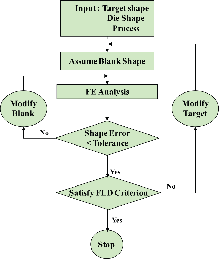
Flowchart of digital tryout for beadless stamping.
Despite evident advantages, beadless stamping is not yet widely applied in industry and is not cited in the literature. The reasons are that beadless stamping is still in situ, and most engineers believe it is difficult to control the deformed shape. In general, if a blank shape is given, then the deformed shape can be predicted with high accuracy, which is a main function of commercial stamping process analysis software programs. In contrast, finding an initial blank shape corresponding to a desired deformed shape with high accuracy (namely, the optimal blank design) is difficult.
Many methods of optimal blank design have been devised, and these can be classified into two groups: retro-marching schemes and iterative schemes. Most of the optimal blank design method belongs to the retro-marching group. 3 –8 In this group, an initial shape, the optimal blank, is derived in a straightforward manner from a given final shape. However, the retro-marching scheme shows limited accuracy since there is no way to compensate shape error (the difference between the desired final shape and the deformed shape from finite element (FE) analysis) with the predicted initial shape.
In contrast to the retro-marching scheme, in the iterative scheme, an initial shape guess is iteratively modified considering the magnitude of the shape error until the deformed shape is in agreement with the desired final shape. Starting from the sensitivity method, 9 the iterative schemes have been evolved into the radius vector method 2 via the initial nodal velocity method 10 by the present author. Since these methods show excellent accuracy and convergence, they have been successfully applied to optimal blank design for the initial blank design of auto part stamping involving complicated shapes.
If the material or shape of the part is difficult to form, the success of the stamping process is highly sensitive to the blank shape, especially the contour of the deformed shape. Therefore, the deformed contour and the corresponding blank shape should be carefully controlled if the part is difficult to form. In this study, the radius vector method, which has been proven to be fast and accurate, has been exploited to meet the requirements of the blank shape.
In the general stamping process, the product is obtained by a trimming from the deformed shape. As the trimmed area increases, the required blank area increases and the formability of the stamping process decreases. In order to optimize the stamping process beyond the stamping, the deformed shape after stamping (and hence the target shape) should be as close to the shape of the part (hereafter the punch contour) as possible.
When the deformed shape is close to the punch contour, the area gripped by the binder and die decreases. During stamping, the rigid body movement of the blank is restricted by the friction forces between the blank and die. If the gripped area is small, the balance of the gripped area surrounding the punch is easily broken even if a small deviation in the blank position occurs. The imbalance of the gripped area affects the balance of the frictional forces that hold the blank. Therefore, even a small deviation in the blank position can cause very different deformed shapes and hence contours.
Figure 2 shows the effect of deviation in the blank’s position on the deformed shape. Figure 2(a) shows the punch shape and the blank shape. The blank shape was derived using the radius vector method from a given target shape, flange of uniform width surrounds the punch. In order to show the effect of the blank position, the deformation process was carried out with a shifted blank. Figure 2(b) shows the deformed shape of the blank shifted upward by 2 mm, and Figure 2(c) shows the deformed shape of the blank shifted downward by 2 mm. Both deformed shapes show very different results. In one, the bottom edge is open, and in the other, the top edge is open. If the amount of shift, 2 mm, is compared to the blank size (around 1300 mm in width and 900 mm in height), the amount of shift can be considered negligible. A small deviation in blank position causes significantly different deformed shapes.
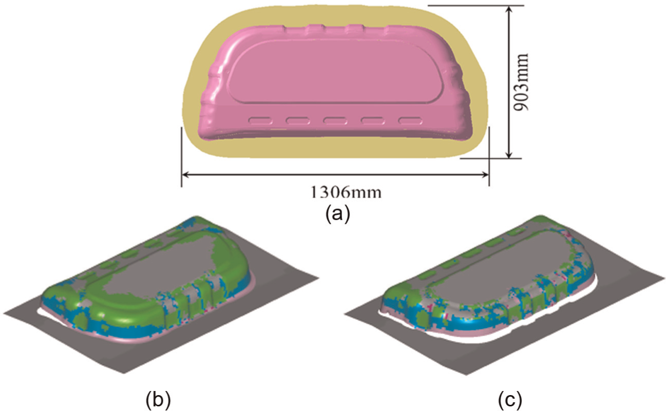
Effect of blank position on the final shape: (a) optimal position, (b) shift up (+2 mm), and (c) shift down (−2 mm).
The reason why this phenomenon occurs can be ascribed to frictional forces. As the deformation progresses, the blank area gripped by the binder decreases. If the gripped area is small, the deviation in the blank’s position influences the significantly imbalanced gripped area around the punch, and the imbalance of this area causes the imbalance in the frictional force. During stamping, the force imbalance causes successive rigid body motion of the blank. As the blank area is decreasingly gripped by the binder (i.e. the target shape is small), the phenomenon becomes stronger. Since this phenomenon—the sensitivity of deformed shape to blank position—is closely related to the difficulty of tryout, a countermeasure of the sensitivity should be considered to realize a beadless stamping.
If the rigid body motion of the blank is restricted to some degree, then the sensitivity could be lessened. Then, the use of a drawbead is considered again. In this case, the purpose of the drawbead is to prevent rigid body motion and not to control metal flow. Therefore, the position of the drawbead can be somewhat freely selected, and the work required for the modification of the drawbead is not required during the tryout stage.
Ultimately, the goal of the proposed digital tryout method is to find an optimal stamping condition by iterative trials of the target shape, whereas a classical tryout in the real world is an iterative modification of the drawbead and blank shape. If the target shape is given, the initial blank shape, namely, the corresponding optimal blank shape, is found. With the optimal blank shape, the simulation of the stamping process is carried out and the predicted quality of the deformed shape is examined from the formability point of view.
Since beadless stamping is an iterative process, the number of trials in the digital tryout process can be greatly reduced if the experience of the engineers is used in the selection of the drawbead position and the determination of the target shape.
Results and discussion
The concept of digital tryout for beadless stamping was verified with a real auto part by comparison with the current process. DYNAFORM™ commercial stamping analysis software (Version 5.7.3, Engineering Technology Associates Inc., Troy, MI, USA) was used in this study. The initial blank shape to initialize the digital tryout was found from a predetermined target shape using the blank size estimation (BSE) function in DYNAFORM. Initially, with the obtained blank shape, the deformation process was analyzed. The shape error between the deformed shape and the target shape was measured at every node on the contour until the error reached a specified shape error allowance at every node on the contour. If the shape error exceeded the allowance, the blank shape was modified based on the magnitude of the shape error. A more detailed explanation of the radius vector method is given in the study by Shim. 2
Figure 3(a) shows the die geometry of a radiator support lower member. The main characteristics of this example are that the binder surface has two steps and doubly bended nearly vertical wall is designed at the straight edges. Because of the characteristics of the shape, a strong possibility of wrinkling and fracture was expected over a wide region. In the original design, the blank shape is rectangular (SGC340, 0.7 mm, 1030 mm × 230 mm) and the drawbead was installed 10 mm from the punch opening line, as shown in Figure 3(b).
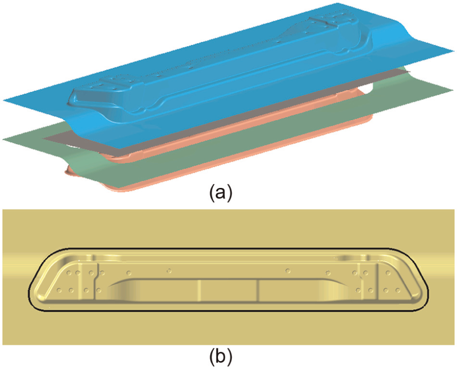
Original stamping dies (radiator support lower member): (a) drawing die set and (b) top view to show drawbead line.
Figure 4 shows the forming limit diagram of the original design, determined with the function of DYNAFORM, where severe fracture was expected to occur near the straight vertical wall. The reason for the severe fracture is ascribed to the excessively large blank size and the drawbead, both of which impede metal flow.
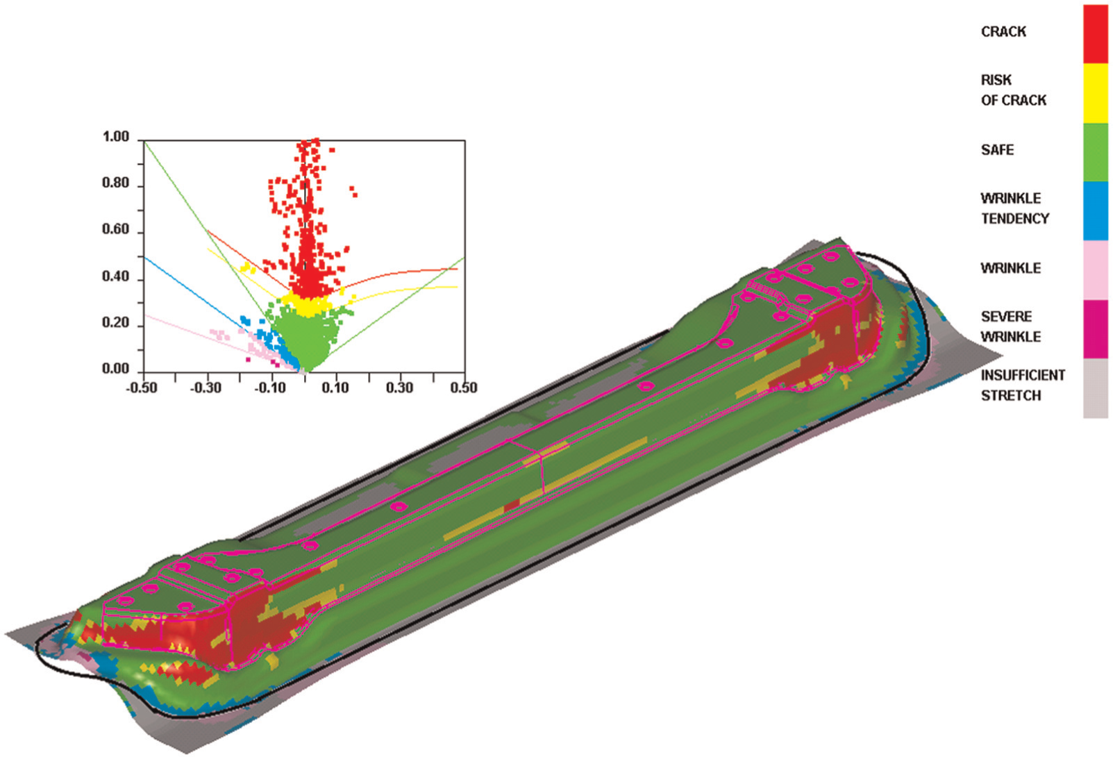
Forming limit diagram of original design.
The author applied the proposed digital tryout in combination with beadless stamping to solve the fracture problem. Compared to the length, the shape of the part is narrow in width and deep in height. If the drawbead is removed completely, then the contour of the deformed shape will be moved sensitively with respect to the change of blank shape especially along the width direction, as shown in Figure 2. If the contour moves sensitively according to a minute change in blank shape, then the optimal blank design and the tryout become difficult. This is the main reason why the engineers and technicians prefer drawbead, as mentioned previously. To prevent this problem, a measure of stabilization is required. Therefore, a line of drawbead was installed on one side of the straight edge in order to restrict the blank from moving freely, especially along the width direction, as shown in Figure 5(a).
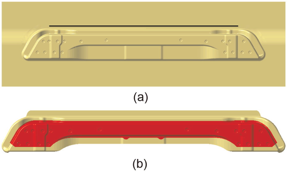
Modified design for beadless stamping: (a) drawbead line and (b) comparison of product shape and target shape.
If a pair of drawbead is installed on the opposite sides of the punch, as in a typical use, extra pulling force due to the drawbead is exerted over the deforming region during stamping. For a successful stamping, these drawbeads should be adjusted carefully in order to control material flow over the entire region. However, the drawbead was installed on one side in the beadless stamping. Due to the drawbead, the blank would not slide over the drawbead easily, without generation of extra pulling force on the opposite side. Thus, the function of the drawbead in the beadless stamping became the stabilization of the blank position rather than flow control.
Figure 5(b) compares the desired formed shape (i.e. the target shape) and the part shape. The target shape shown in the figure was determined by the examination of deformation analysis results through trial and error.
The blank shape to be deformed into a desired shape (i.e. the optimal blank) was found using the radius vector method until the maximum shape error became less than 10 mm at every node on the contour. The magnitude of allowable shape error can be decided by the engineers considering the degree of improvement by the digital tryout, characteristics of deformation behavior of the part, allowable development period, and so on.
Figure 6(a)–(c) shows the progress of the optimal blank design by comparing the undeformed shape, target shape, and deformed shape, starting from the first design blank shape determined with the BSE function of DYNAFORM, the second design, and then the third design, respectively. As the design stages developed, the deformed shape became closer to the target shape. The shape error reached the shape error allowance at every boundary node after the second modification, resulting in three cycles of deformation analysis. After three cycles, the blank shape was chosen as the optimal blank of the given target shape. Figure 6(d) shows change of the shape error during the evolution of optimal blank design. Since the shape error is measured at every node on the contour, the shape errors are different from node to node. Max. error refers to a maximum value among all the shape errors and root mean square (RMS) error refers to root mean square value of shape error. At the third design stage, the Max. error became less than 10 mm and the RMS error was about 3 mm. This implies that the deformed shape almost coincides with the target shape except for some nodal point.
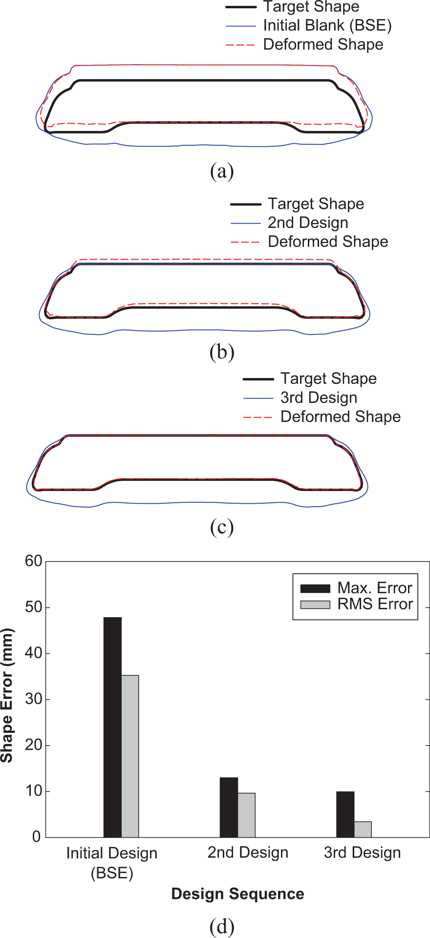
Evolution of optimal blank design stage: (a) initial design (BSE), (b) second design, (c) third design (optimal blank), and (d) change of shape error.
Figure 7 shows the optimal layout of the optimal blank to obtain the optimal sheet metal usage, where the minimum required area per blank was found to be 1042 mm × 195 mm. Figure 8 shows the forming limit diagram of the optimal blank. Comparing this diagram to Figure 4 (the original design), the results of beadless stamping reveal a dramatic improvement, although some possibility of wrinkling still remains.
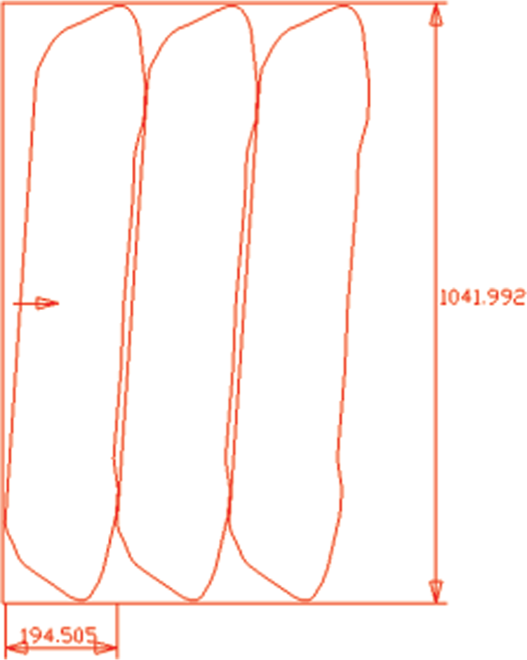
Optimal nesting of optimal blank shape.
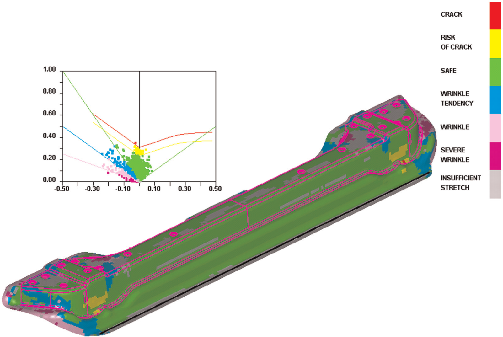
Forming limit diagram (FLD) (beadless stamping).
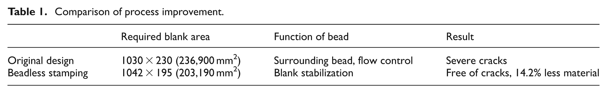
In Table 1, the effect of the proposed method is compared to the original design. In the original design, a severe crack is predicted in the blank shape, which is a rectangle with dimensions of 1030 mm × 230 mm. However, in beadless stamping, the required sheet metal area per blank is reduced by 14.2% and the possibility of a crack is eliminated.
Comparison of process improvement.
The author concludes that the proposed method not only saves significant amount of material but also simplifies the tryout stage. In the proposed digital tryout for beadless stamping, the function of the bead is stabilization so as to prevent rigid body motion (and not to control metal flow), which makes bead modification work quite easily during the tryout phase.
The work required for blank shape determination in the actual tryout stage is expected to be reduced significantly because the digitally determined optimal blank does not deviate significantly from the blank shape that is determined through after actual world tryout.
Conclusion
In this study, a method of digital tryout to realize “beadless stamping” has been developed with two major ideas, the deformed shape control and stabilization of blank. In the proposed method, the desired deformed shape, rather than the initial blank shape, is a major control tool. In order to find blank shape that transforms into the desired shape, optimal blank design technique has been used. Since the drawbead, which is used for flow control, is eliminated in the stamping dies, the required work during the tryout for drawbead modification is eliminated and the less size of blank is required. However, oscillation of deformed shape has been found during the tryout stage when the drawbeads are completely removed. Since the oscillation phenomenon is related with rigid body motion by the imbalance of frictional force, minimum amount of drawbeads enough to prevent rigid body motion are used in the “beadless stamping.” The validity of the proposed method was confirmed through an application using a real automotive part.
Footnotes
Funding
This work was supported by a 2012 Yeungnam University Research Grant.