
Abstract
Parallel tubular channel angular pressing is a novel severe plastic deformation method for producing ultrafine-grained metallic tubes. The objective of this work is to determine the residual stresses in parallel tubular channel angular pressing processed tubes using an incremental blind hole drilling with digital shearography instead of conventional hole-drilling method of strain gauges. Shearography is a full-field speckle interferometric method employed to measure both in-plane and out-of-plane displacements. The displacement derivative distribution due to hole drilling is calculated by analyzing unwrapped phase maps. Using image processing fringe analysis, the optical data involved in the displacement derivatives are converted into the values of residual stresses. The results have shown that an increase in the number of parallel tubular channel angular pressing pass would lead to a decrease in residual stresses that attributed to the low stress gradients along the thickness and length of the parallel tubular channel angular pressing processed tubes. Comparison of the residual stress values obtained from the shearography method with those from finite element modeling has shown good agreement of the stress values, indicating the suitability of shearography technique for stress evaluations in the parallel tubular channel angular pressing process.
Introduction
Residual stress is an unavoidable phenomenon that occurs during the manufacturing process. Thermal and mechanical operations such as those in welding, machining and forming are the main sources of residual stress in processed products. This residual stress remains even after the external load is removed. The remaining stress reduces efficiency, load-bearing capacity and longevity structural integrity of processed products. However, residual stress can be beneficial in special condition. For example, application of compressive residual stress can improve fatigue resistance capabilities of components under variable loadings. In other instances, the presence of residual stress can decrease crack propagation. 1 Due to these facts, finding a good method for determining and analyzing residual stress is essential.
The techniques used to determine residual stress can be divided into two categories of destructive2,3 and nondestructive methods. In addition to physical evaluations, computational methods have also been used to predict the extent of residual stresses in the material. The choice of methods would generally depend on the design of the part.
Previous researchers have used various nondestructive techniques in the determination of residual stress. The nondestructive techniques such as X-ray diffraction and neutron diffraction have some advantages as well as limitations. For example, both are limited to crystalline materials, and the X-ray diffraction is useful only for near-surface stress. A practical technique known as hole-drilling method is capable of providing reasonable accuracy with higher reliability.4–6 It is semi-destructive method where the damage caused is localized and does not significantly affect the properties of the workpiece. The method involves placing a strain gauge rosette at the point where residual stresses are to be determined on the workpiece and drilling a small, shallow hole through the geometric center of the rosette. The removal of the material by drilling relieves the residual stresses within the material, which can be measured by the strain gauge.7,8 The procedure follows American Society for Testing and Materials (ASTM) test standard.
Nevertheless, this method has several drawbacks. Some of them are a requirement for a smooth and large surface to install the rosettes, the sensitivity of rosette to heat and limitation of the reading to only point measurement. Improvements to this method have focus on replacing the strain gauge sensor with optical measurement devices. These include full-field optical techniques such as shearography, Moiré interferometry, electronic speckle pattern interferometry (ESPI), holographic interferometry and digital image correlation (DIC). Shearography is one of the most effective optical methods for determining residual stress, which utilizes coherent light to measure displacement gradients, and hence the strains at the surface of the workpiece material. It was initially proposed in 1990s by Hung et al. 9 They used Kirsch solution and subsequently combination of shearography and hole drilling to include the ability to calculate residual stress. Wu and Qin 10 used this method and presented acceptable results. Recently, Montay et al. 11 introduced a new version of this method and utilized the grating in front of the specimen surface with the combination of shearography and hole drilling to compute the amount of residual stresses produced by shot peening.
These noncontact residual stress evaluation techniques are especially suited to investigate the simultaneous microstructural and stress state changes induced in severe plastic deformation (SPD) processes. During the SPD process, the workpiece is subjected to intense plastic deformation resulting in the production of bulk ultrafine-grained (UFG) materials. 12 Different techniques have been proposed by researchers to improve material properties by grain refinements using SPD such as equal-channel angular pressing (ECAP), 13 accumulative roll bonding (ARB) 14 and high-pressure torsion (HPT). 15 There are many variants to the SPD techniques, all of which were developed to produce UFG and nanostructured (NS) materials 16 having superior mechanical properties. SPD techniques based on the extrusion process are more attractive than other techniques because of the capability of applying large deformation. This privilege resulted in developing new SPD techniques based on the extrusion process such as twist extrusion (TE), 17 cyclic extrusion and compression (CEC), 18 simple shear extrusion (SSE) 19 and torsion extrusion. 20 Most SPD methods are used for non-tubular form metals like bulk and sheet parts. 21 In spite of the high need of tubular components in industrial applications, handful investigations have been done in this regard. Toth et al. 22 proposed an SPD process based on HPT for producing UFG tubes. It seems that the process by Toth et al. may have some limitations such as low homogeneity. Mohebbi and Akbarzadeh 23 developed an accumulative spin-bonding (ASB) method based on ARB to produce UFG tubes. Faraji et al. 24 proposed tubular channel angular pressing (TCAP) as an effective method for producing UFG and NS tubes. Recently, Faraji et al. 25 introduced a new SPD process named parallel tubular channel angular pressing (PTCAP) to produce high-strength UFG tubes. Figure 1(a) and (b) shows the schematic illustration of PTCAP process consists of two half-cycles. During each half-cycle of the process, two consequent shear strains are applied to the tube materials (Figure 1(c)). Applying these intense plastic shear strains could refine the microstructure to the submicron range, and the whole process can be repeated to achieve a distinct strain. The evaluation of residual stress induced during SPD is important since this stress will affect the final performance of the component. In this article, digital shearography technique was used to measure the residual stress in UFG aluminum tubes produced by PTCAP method. Numerical simulations of the PTCAP process were also conducted to calculate the residual stress that can then be compared to the experimental results obtained.
Principles of the PTCAP process in the (a) first and (b) second half-cycles and (c) parameters.
Principles of shearography
Shearography is a noncontact method, measuring gradient of displacements, and it has lower sensitivity to vibration in comparison with other optical methods. Figure 2 shows a schematic of dual-beam digital shearography setup. In this arrangement, the test object is illuminated by a laser beam and the reflected light passes through a Michelson interferometer. The interferometer first splits the beam into two and then uses two mirrors to create two laterally sheared images. These images interfere with each other in front of charge-coupled device (CCD) camera creating an interferometric speckle pattern. 26 During the deformation of test object, the phase difference between two adjacent points changes and can be obtained using the following equation 27
where Δφ is the phase difference between before and after deformation; λ is the wavelength of the laser beam; θ is the angle between normal vector of object surface and direction of illumination; δx is the amount of shear induced to Michelson device and
Schematic of dual-beam digital shearography setup.
It should be noted that the above equation is related to the object, which is illuminated in x–z plane and sheared in x direction. For obtaining
Residual stress determination
Hooke’s law and Krisch’s equation
30
are used as a basis to express the released stress in drilled hole. The magnitude of the released stress relief due to hole drilling in a specimen under
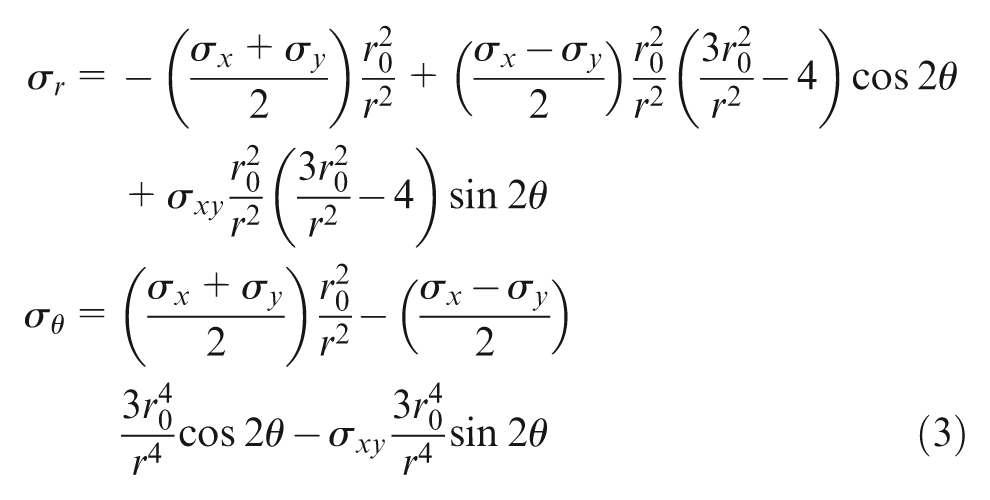
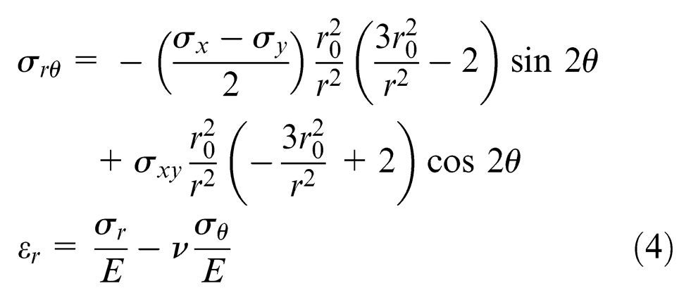
where r
0 is the radius of drilled hole, r is the radial location at which the derivative displacements and
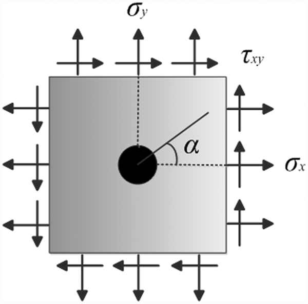
Stress state of thin plate.
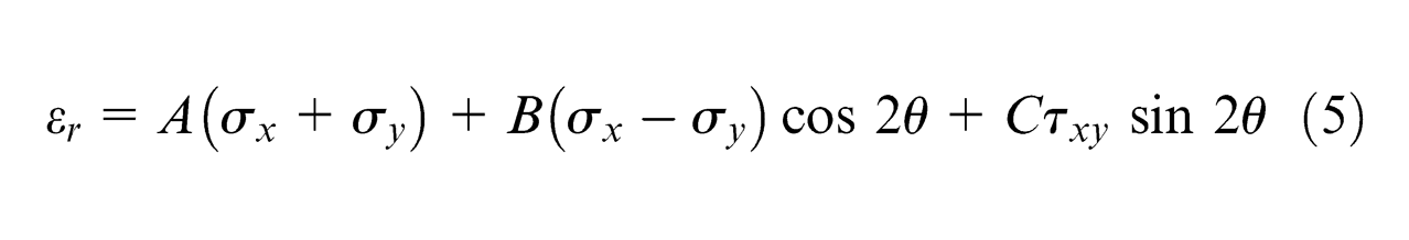
The use of incremental blind hole-drilling (IBHD) method has been proposed, where the hole depth is divided into equal increments and released stresses are measured at each step. Equation (6) shows the relation between residual stress and released strain at different increments in IBHD method
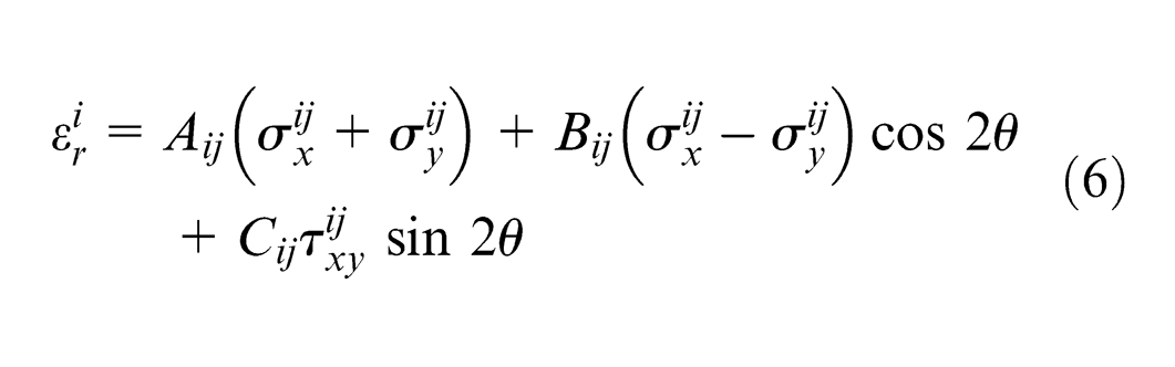
where
Numerical and experimental procedures
FE modeling of PTCAP process
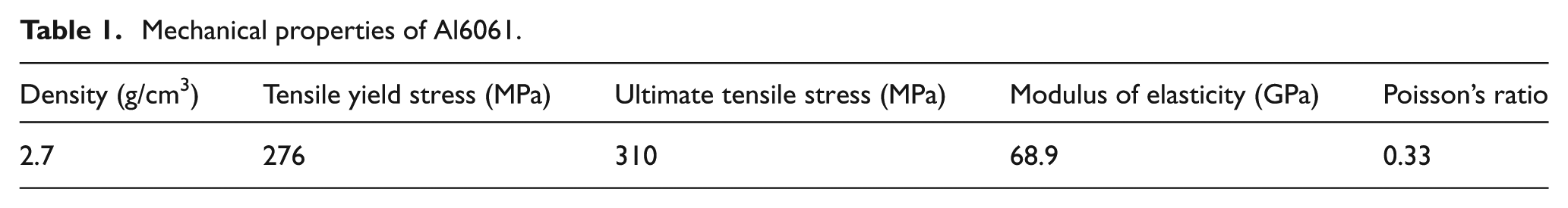
A 3D model was developed in ABAQUS/Explicit commercial FE code to simulate the PTCAP process. To reduce processing time, only a quarter of the tube was modeled with the symmetry conditions defined on the longitudinal planes. Eight-node hex-dominated elements with reduced integration formulations were utilized for tube simulation, while the die, mandrel and punches were assumed to be analytic rigid shells. The mechanical properties of the Al 6061 specimens were determined through a compression test at a strain rate of 2 × 10⁻⁴ at room temperature, and the stress–strain curve data were incorporated into the FE code. These mechanical properties are shown in Table 1. Surface-to-surface contact with finite sliding formulation was defined between tube and rigid components. Penalty formulation was used to define contact property and the Coulomb friction coefficient was assumed to be 0.05. Figure 4 shows the meshed tube and the mechanical components as in 3D simulation of PTCAP process. In order to show the meshed tube more clearly, the die is not shown in this figure.
Mechanical properties of Al6061.
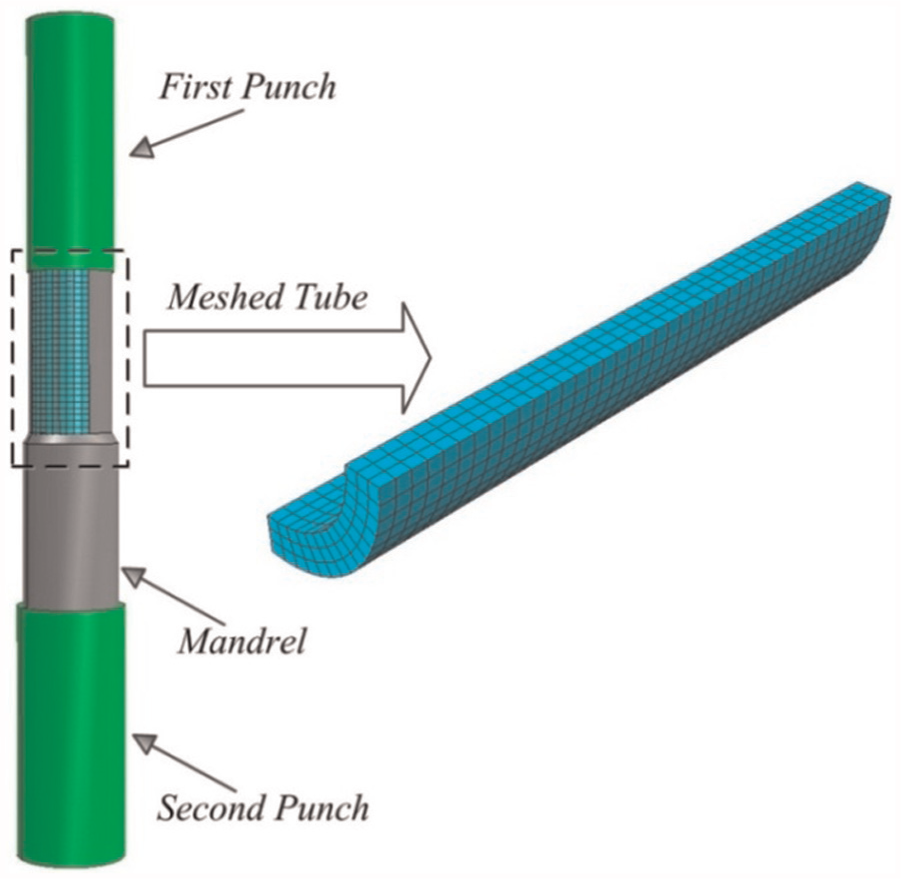
PTCAP process simulation and mesh refinement of tube.
PTCAP processing of UFG tube
The material used for this research is Al 6061 in the tubular form, measuring 2 mm in thickness, 20 mm in diameter and 40 mm in length. The tube was plastically deformed by multi-pass PTCAP technique. Punch speeds in both half-cycles are 5 mm/min, and the process was conducted at room temperature. The channel angle and angle of curvature of die are
Shearography experimental setup
A dual-beam digital shearography device equipped with high-resolution digital camera was used in this research, as shown in Figure 5. The apparatus was setup on an anti-vibration table to reduce noise and interference. A 25 mW He-Ne laser (λ = 633 nm) was used to illuminate the surface of the object, and the resulting speckle pattern was captured using a CCD camera (Art-Cam 320p equipped with a Fujian 55 mm lens), capable of recording images at 2288 × 1700 pixels resolution. A correlation algorithm was then applied to the obtained speckle pattern to determine fringe pattern. Since drilling process should have a high degree of accuracy, the design of hole-drilling mechanism is very important. First of all, this mechanism should prevent from any external stresses that may be produced during the drilling process. Second, using theoretical relation for determining residual stress required to have flat and circular shape hole. Furthermore, during the experimental test using shearography method, the drilling system should have the capability of moving on both x and y directions; thus, a transitional base possessing two-dimensional movements is required.
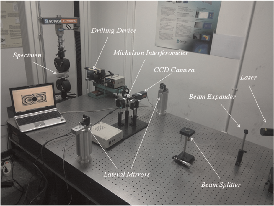
Dual-beam experimental shearography setup and drilling mechanism.
To satisfy all these characteristics, a drilling mechanism has been designed, as shown in Figure 5. As shown in this figure, the drilling device that has a top speed of 60,000 r/min has been rigidly fixed on the top of translation base using bolt and nut. When the images were recorded, the drilling system is brought back to the initial position and hole is drilled into object up to desired depth. One of the main important factors that affect the quality of drilled hole is drill-bit speed. Based on the recent researches that suggested drilling speed in the range of 14,000–40,000 for having the desirable results, 31 in this investigation, the drill-bit speed of 35,000 has been used.
An IBHD was selected in this process in which a blind hole with radius of 0.5 mm was incrementally drilled in the middle of the specimen. Three-step process, each step with an incremental depth of 0.2 mm, was taken in drilling to reach the final depth of 0.6 mm. The speckle patterns of the drilled surface were recorded after each drilling step. A correlation algorithm was used to determine the fringe pattern by subtracting the before-drilling and after-drilling speckle patterns. If the object surface illumination and shear direction lie in x–z plane and x direction, respectively, the phase differences relating to displacement gradient in the x direction could be calculated. Similarly, by illuminating and shearing along y–z plane and y direction, respectively, the surface derivative of displacements in y direction could then be obtained.
Results and discussion
Numerical simulations were conducted to calculate residual stress during PTCAP process. Figures 6 and 7 show the contours of circumferential and axial residual stresses after each pass of PTCAP. As shown in Figure 6, the circumferential residual stress at the top section of the tube is in tensile while it is compressive in the lower and middle sections. The difference in circumferential stress values between the upper and lower parts of the tube varies significantly. Significant decrease in circumferential stress was seen on the second-pass PTCAP processed sample. However, only slight reductions in circumferential stress were observed for the subsequent third and fourth passes.
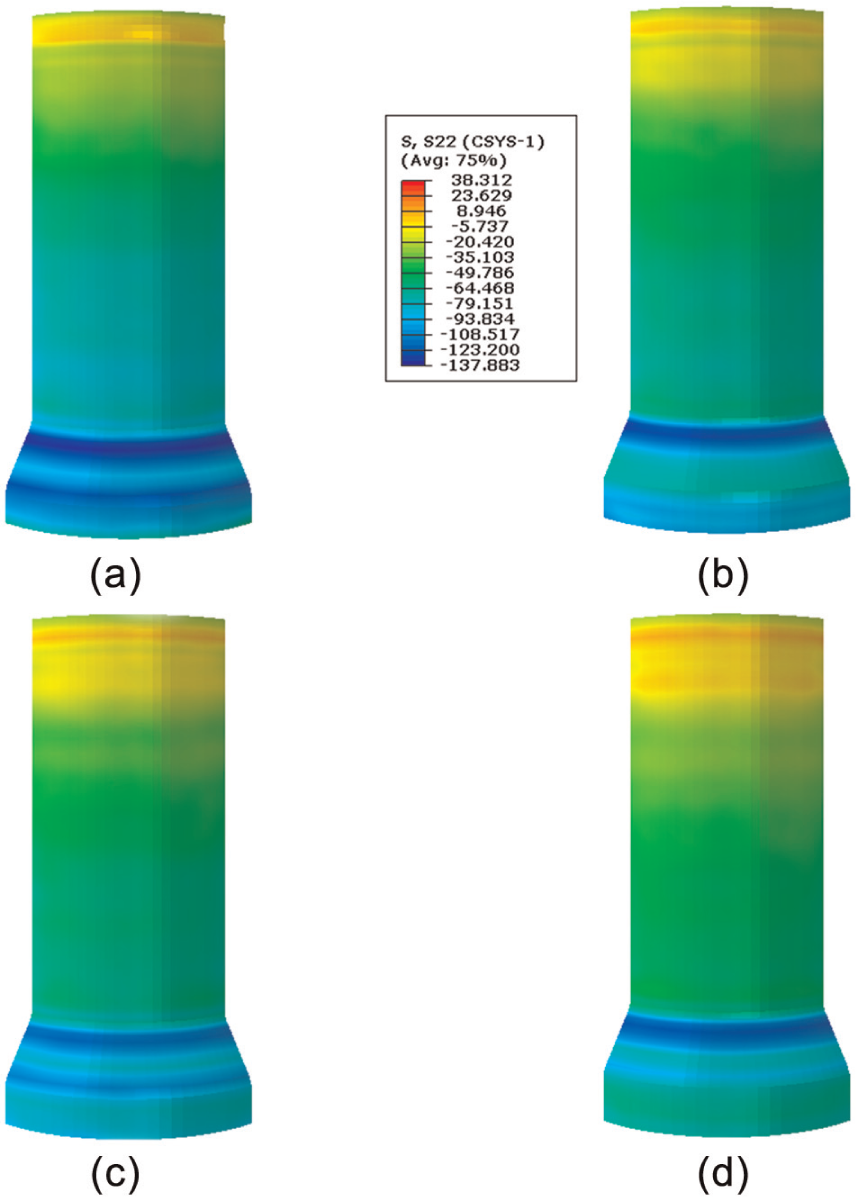
Circumferential residual stress contours of (a) one-pass, (b) two-pass, (c) three-pass and (d) four-pass PTCAP process.
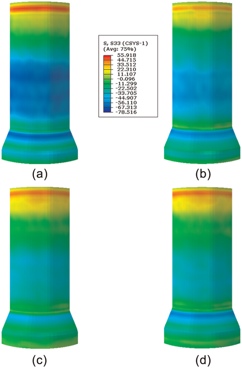
Axial residual stress contours of (a) one-pass, (b) two-pass, (c) three-pass and (d) four-pass PTCAP process.
Figure 7 shows the distribution of axial stress, which has a similar trend to circumferential stress observations. Significant reduction in axial stress was seen on the second and third PTCAP passes. However, a small reduction in axial stress was seen in the fourth pass.
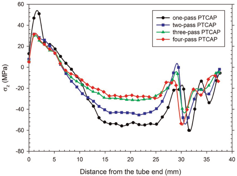
Figure 8(a)–(d) shows the variation in axial and circumferential residual stresses along the axial direction, calculated using numerical simulations, for different PTCAP passes. As it is observed, the magnitude of residual stresses along the axial direction for all passes is almost constant. However, there are stress variations at both ends of the tube, 32 probably due to these areas not passing through the complete loading cycle. In general, compressive residual stresses are dominant on the surface of specimen. This is probably caused by frictional forces acting against the direction of movement and inhibits the flow of material, subsequently generating the compressive residual stress. 33
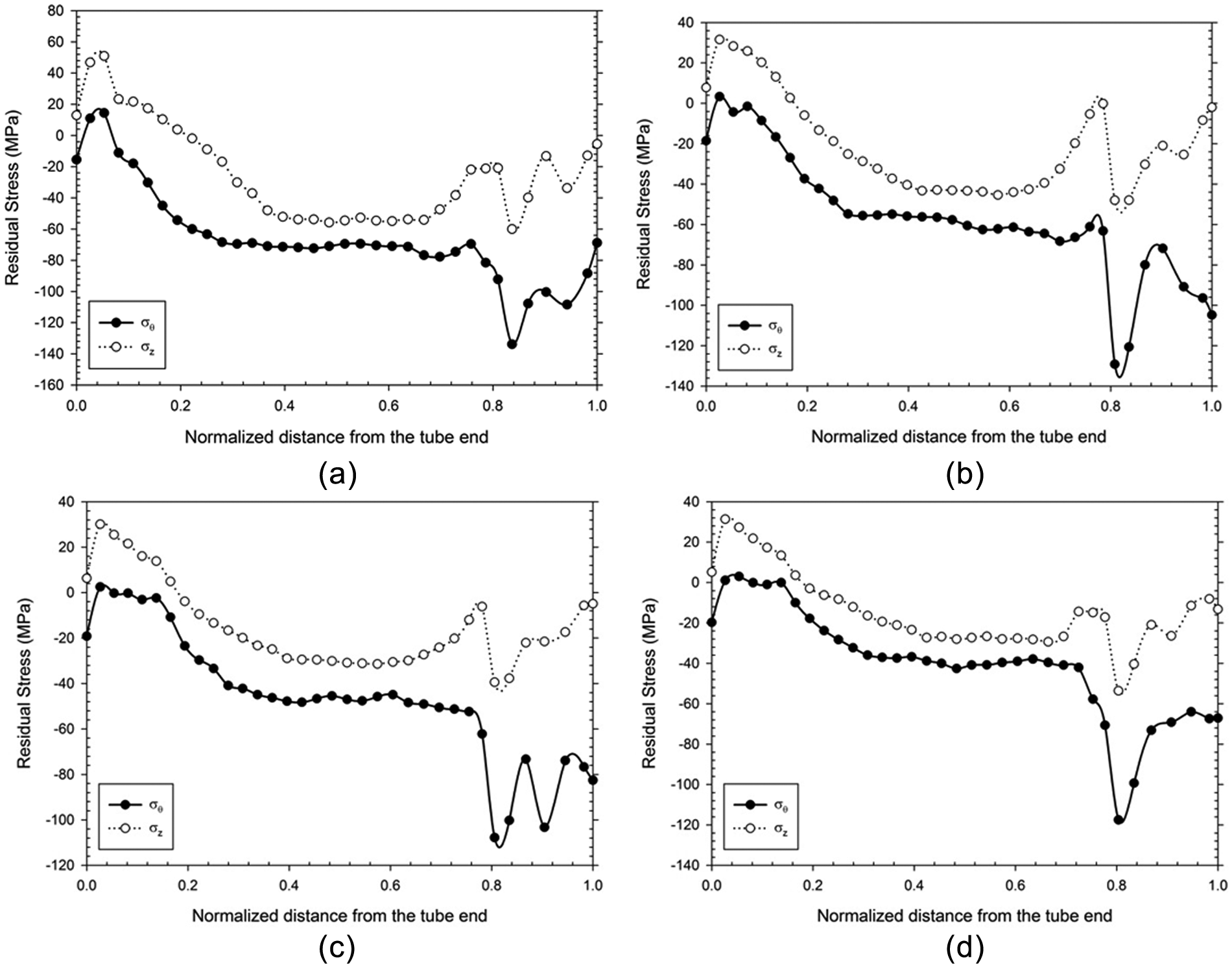
Variation in residual stress along with the axial direction: (a) one-pass, (b) two-pass, (c) three-pass and (d) four-pass PTCAP.
Comparisons between the calculated values for the axial and circumferential residual stresses at different numbers of PTCAP passes are shown in Figures 9 and 10, respectively. It can be seen that as the PTCAP pass increases, the magnitude of both axial and circumferential residual stresses decreases. This may be the result of decreasing gradients of axial and tangential stresses along the thickness of the tube, which subsequently reduces the value of residual stress. 34 As can be seen from Figures 6, 7, 9 and 10, there is a strange result for both the ends of the specimen, which it mainly refers to the space limitation of mandrel movement. So both ends are not under fully shear strain. This leads to change in residual stress, so data obtained for these regions are not reliable. It should be noted that this restriction exists also in other SPD methods such as TCAP, ECAP, CEC and SSE.13,18,19,24 The IBHD process conducted involved drilling a blind hole with three incremental hole depths of 0.2, 0.4 and 0.6.
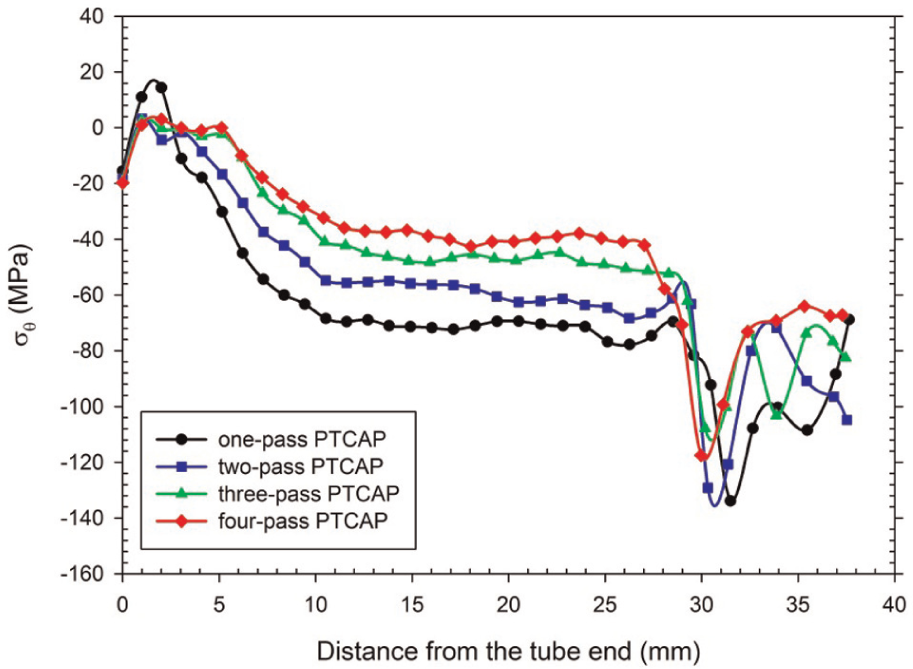
Comparison of circumferential residual stress along the axial direction produced during PTCAP passes.
Comparison of axial residual stress along the axial direction produced during PTCAP passes.
The phase patterns of before-drilling and after-drilling for each step were recorded from which the strain distribution field can be determined. Figure 11 shows the strain distribution fields obtained for each incremental hole depth. It is seen from the figure that the raw image captured contained a lot of image noises. A low-pass filter was used to sharpen the image, and then the location of the blind whole is masked in the fringe pattern. A wavelet transform is applied to determine the wrapped phase of the fringe pattern, as shown in Figure 12. Then, an unwrapping process is applied on the fringe pattern to obtain a continuous unwrapped phase map, as shown in Figure 13. The residual stress can be calculated based on the unwrapped phase pattern and the calibration coefficient obtained by numerical methods.
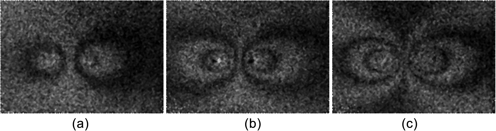
Fringe pattern obtained from three incremental hole drilling after drilling depths of (a) 2, (b) 4 and (c) 6 mm.
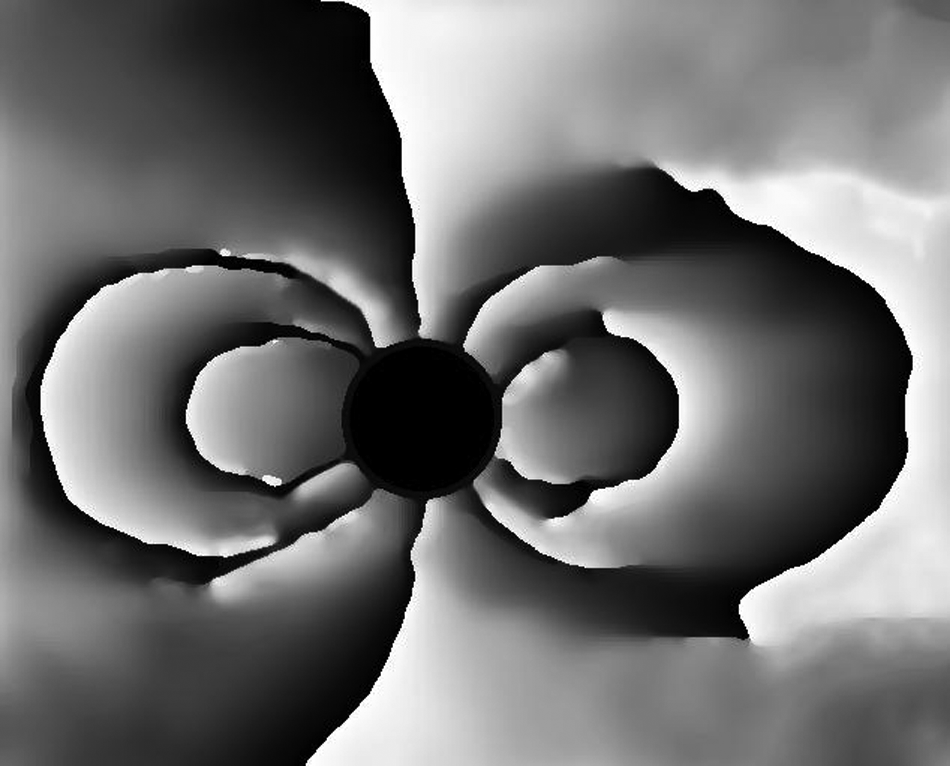
Wrapped phase of the fringe pattern obtained by wavelet transform for drilling depth of 0.6 mm.
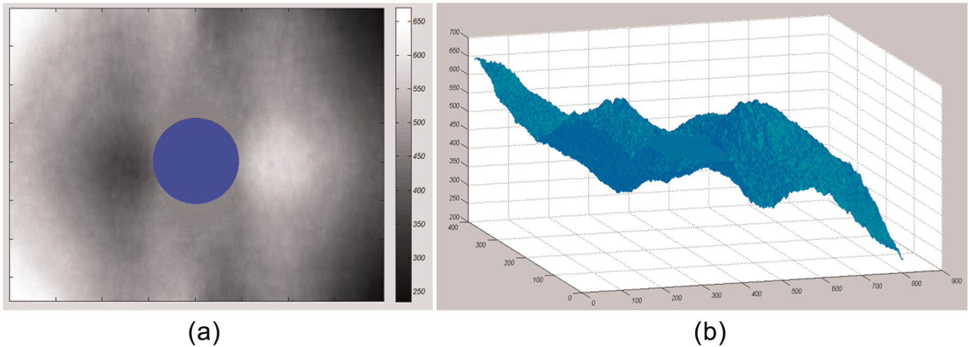
Results of unwrapping phase algorithm: (a) unwrapped phase image and (b) 3D MATLAB rendering of the unwrapped phase image.
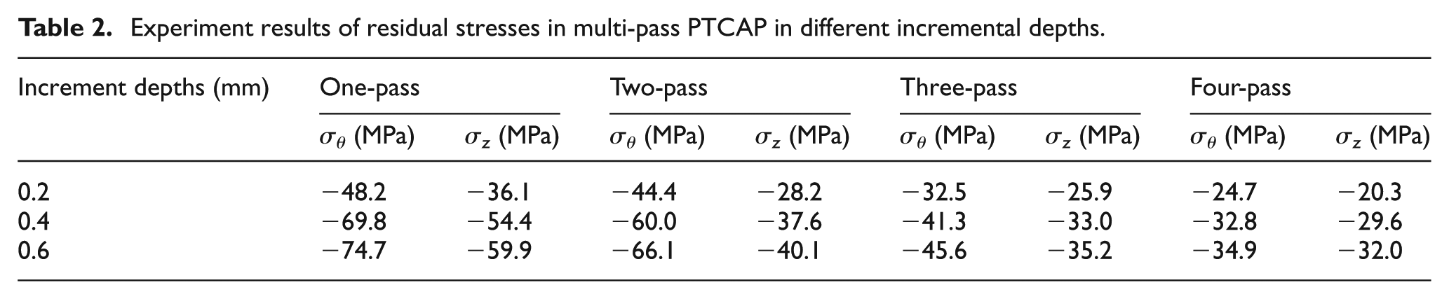
Figure 14 shows a sample of the final contour along the axial direction for 0.6 mm hole depth obtained from processing of the unwrapped phase pattern. The residual stress is calculated from a selection of 20 points within the vicinity of the desired strain distribution field. A combination of least square over determination method and equation (6) is used to compute the residual stress. The residual stress at different incremental depths was calculated and shown in Table 2. Generally, it is seen that the amount of residual stress increases linearly with an increase in the drilling depth. Moreover, analysis has shown that after the 0.6 mm drilling depth, all the confined stresses are released, and no subsequent changes in residual stress are observed. Table 2 also shows that the amount of released stress decreases as the number of pass increases, which agrees well with the results of numerical calculations. Figures 15 and 16 show the comparison of numerical and experimental results of circumferential and axial residual stress measurements, respectively.
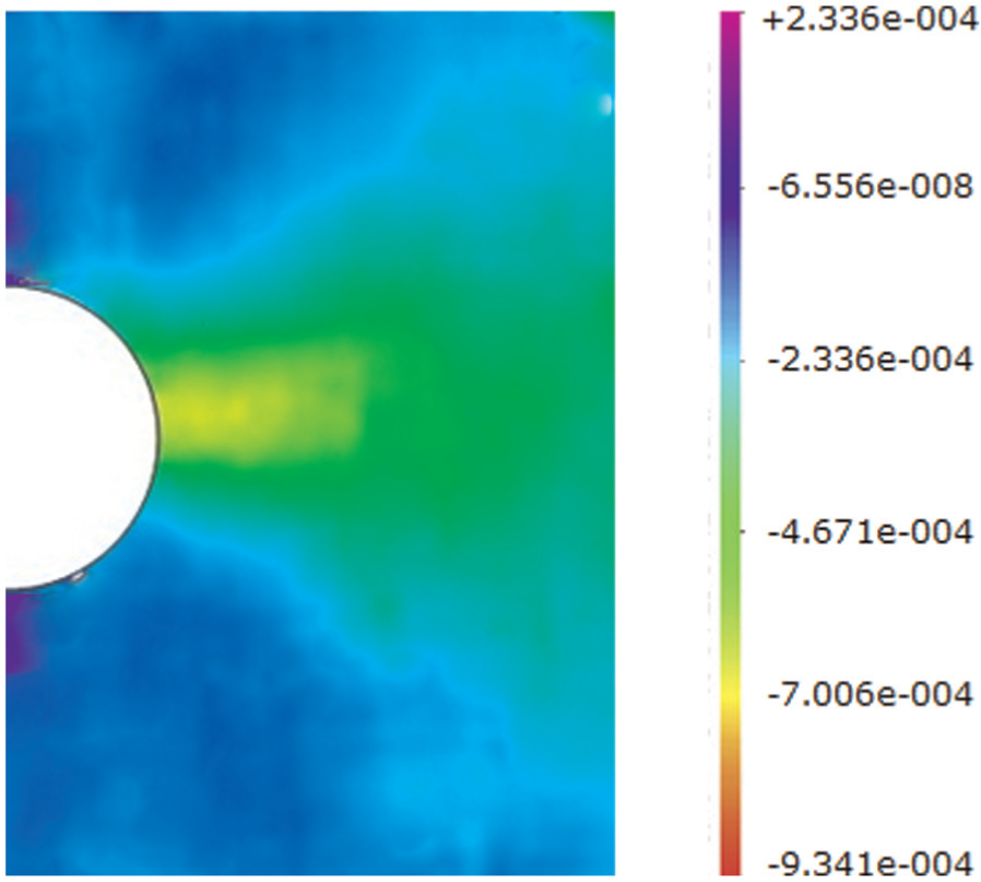
Released strain distribution field obtained from processing of unwrapped phase map.
Experiment results of residual stresses in multi-pass PTCAP in different incremental depths.
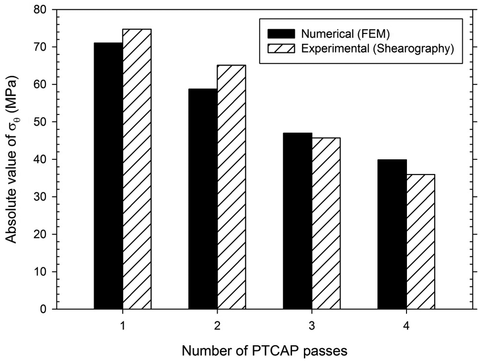
Comparison of numerical and experimental results of absolute values of circumferential residual stress.
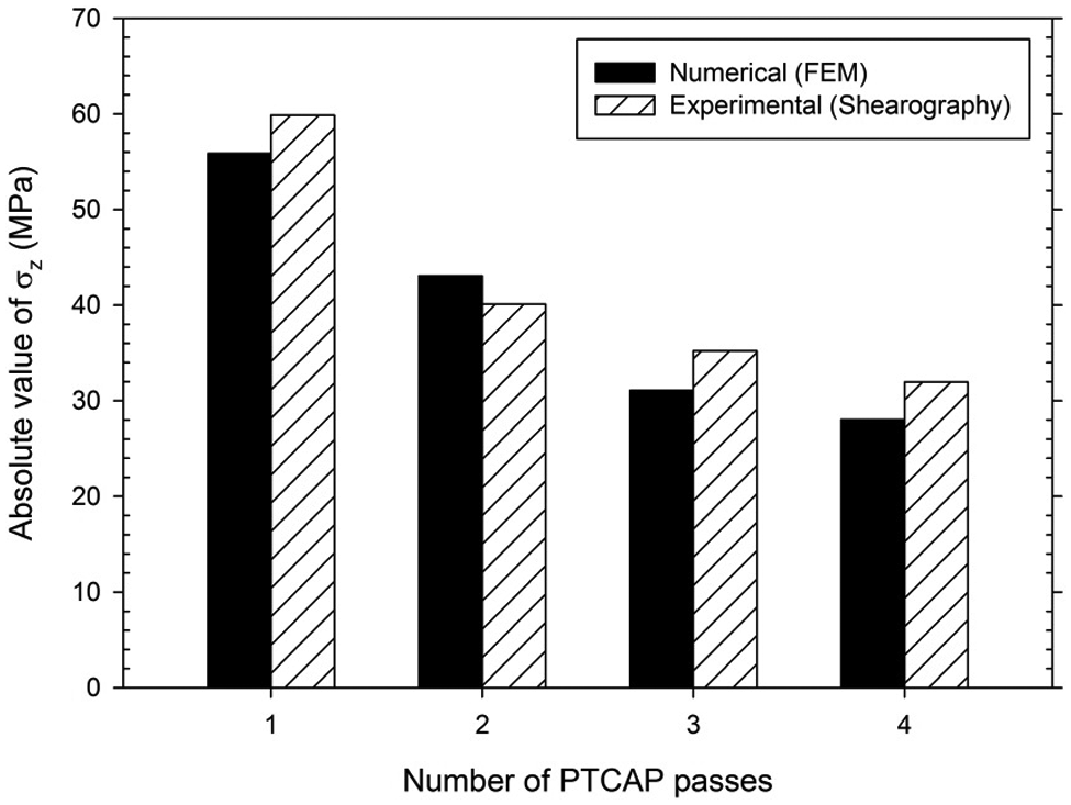
Comparison of numerical and experimental results of absolute values of axial residual stress.
The differences between numerical and experimental results are within the range of 3%−10.5%. Thus, it can be concluded that there is good agreement between experimental and numerical solutions. This also shows that shearography method can be utilized for evaluation of residual stresses of the PTCAP procedure with acceptable accuracy.
Conclusion
A shearography technique was used to determine the residual stress of UFG tubes produced by multi-pass PTCAP. The stress values obtained from shearography readings for incremental hole drilling of the specimen have shown good qualitative agreement with the values obtained from numerical simulations. The results showed the following:
The surface of specimen was dominated by compressive residual stresses with uniform values in all regions except both tube ends.
The residual stress decreases as the PTCAP passes increase.
As the hole-drilling depth increases, the magnitude of released stress raises. All superficial residual stresses were released beyond 0.6 mm hole depth.
Footnotes
Declaration of conflicting interests
The authors declare that there is no conflict of interest.
Funding
This work was financially supported by the Iran National Science Foundation (INSF).