
Abstract
In this research study, a comparative examination on the mechanical properties of AA6063 has been carried out after having been processed by isothermal forging, using plane-shape dies and starting from different initial deformation states. It introduces the novelty of employing experimental data obtained from the isothermal forging so as to model the flow rules of AA6063 processed by equal channel angular pressing taking temperature into account and using artificial neural networks to this end. Subsequently, these flow rules are employed to model the behaviour of AA6063 by means of finite element simulation. Furthermore, a validation of the experimental results is made with those obtained from the simulations using the flow rules attained with the neural networks. It is shown that it is possible to achieve higher precision than with traditional fitting methods of flow rules. In addition, this study presents the novelty of carrying out a comparative study between different starting material states, prior to forging, including among these material previously processed by the severe plastic deformation process, which is referred to as equal channel angular pressing. Moreover, the experimental results obtained when processing the aluminium alloy by equal channel angular pressing are compared to those states, which correspond to the traditional way of working on aluminium alloys, which can be quenched and aged for the purpose of improving their mechanical properties.
Keywords
Introduction
Over these last years, there have been a large number of publications dealing with materials processed by equal channel angular extrusion. 1 Nevertheless, in the present bibliography, there are a limited number of studies focusing on the use of starting material previously processed by severe plastic deformation (SPD) processes and which are then subjected to some other conventional type of plastic deformation process for manufacturing parts. 2 Moreover, there are only a few studies dealing with finite element modelling (FEM) of alloys previously processed through SPD processes for the manufacturing of those parts, which may have complex shapes. On the other hand, the majority of these existing studies use flow rules for materials without taking into consideration the fact that they have been previously obtained by SPD and therefore, that they possess a high value of accumulated plastic strain (ε > 1), which can lead to obtaining inaccurate results in the simulation. In this study, a methodology is shown to achieve flow rules for materials processed by SPD with equal channel angular pressing (ECAP). In addition, a comparative study is made between the mechanical properties obtained from different initial states of AA6063. First, as an initial step in order to attain the results obtained in this research work, a review of the main studies related to this topic is made. Among the research works that could be cited, the study from Chaudhury et al. 3 may be underlined. This article studies the influence of the ECAP process over an AA6061 subsequently hot forged, and one of the most relevant conclusions results in the fact that it is possible to manufacture parts with lower values of forging temperature. Another research work is that by Lee et al., 4 where the manufacturing of an impeller with twisted blades of micro-thickness is analysed in a magnesium alloy AZ31. The grain refinement of the structure to be forged is carried out through a series of ECAP passages at temperature values of 400 °C and 250 °C, respectively. Furthermore, Kim et al. 5 also completed a study on the isothermal forgeability of AA6061. In the research work from Puertas et al., 6 the study of an isothermal forging between plane-shape dies is carried out in the case of an AA5083 aluminium alloy, previously processed by ECAP at room temperature. One of the most significant conclusions of this research work is that the ECAP process improves the forgeability of this type of alloy and also that after the isothermal forging, the microstructure continues to be submicrometric.
A large number of studies focusing on the ECAP-processed aluminium alloys exist but those dealing with heat-treatable aluminium alloys, such as 6xxx, are not so numerous. In the research work by Khan et al., 7 an ECAP processing of AA6063 is carried out, which is subjected to three passages and employing routes A and B. It is shown that with route B, optimum values of mechanical strength and elongation at break for the alloy are achieved. In Khan and Meredith, 8 the thermo-mechanical behaviour of AA6061 is analysed, examining its ECAP processing and the properties attained are compared with the same alloy without any ECAP processing. In the research work by Qian et al., 9 several electronic microscopy techniques are used to characterize the ECAP-processed alloy AA6063. It is shown that in the alloy processed by ECAP twice at room temperature, a significant refinement of grain size is obtained. Regarding the precipitation during the ECAP process of an Al-Mg-Si aluminium alloy, the research work carried out by Roven et al. 10 is of interest as well, where the dynamic precipitation is studied for the ECAP process performed at room temperature and at a temperature of 175 °C and it is then compared to the conventional static ageing process. On the other hand, in the study by Pérez et al., 11 in the case of an aluminium alloy AA6060, the influence of the ageing treatments is analysed on its mechanical properties when it is ECAP processed. After processing the alloy twice and four times with route C, the authors of this research work determine that a temperature of 125 °C is the one which provides the best results in the mechanical behaviour of the latter. A further series of research studies that appear in the bibliography analyse the influence of the ageing treatments on the heat-treatable alloys AA6xxx. So, for example, Siddiqui et al. 12 determine that for the AA6063 alloy, the optimum values of temperature and time in order to achieve the highest values of mechanical strength, yielding point and hardness, are 175 °C from 8 to 10 h, respectively. Gavgali et al. 13 focus their study on the effects of the ageing treatment, also in the case of an AA6063, over its wear behaviour.
On the other hand, Hong et al. 14 and Abid et al. 15 study the effects of diverse pre-ageing treatments, followed by natural ageing at room temperature, over the precipitation hardening of AA6xxx alloys when performing subsequent artificial ageing treatments, through the measurement of the hardness of the treated samples. One of the most relevant conclusions of these research works is that the aged samples, which have previously undergone a pre-ageing and natural ageing process, provide higher hardness values. Other field studies such as that by Utsunomiya et al. 16 propose continuous processes to improve the productivity of the process.
Among the research works existing in the bibliography related to FEM of diverse kinds of aluminium alloys processed by ECAP, one might underline the two carried out by León et al., 17 Luri and Luis Pérez 18 and Puertas et al., 19 in which a comparative study is made between the experimental values and those obtained by FEM in the case of an alloy AA6082, after having been subjected to one and two ECAP passages, respectively. In the case of the first passage 17 and of the second passage, 19 these research works analyse the force required for the ECAP press, the real strain and the accumulated damage, comparing the value of this force with that obtained through a load cell attached to the extrusion punch. On the other hand, the research work carried out by Cerri et al. 20 is also significant where the change on the mechanical properties of two alloys AA6082 modified with Zr and Zr-Sc, respectively, is studied after having been processed with one and four passages by route B. The study is performed by means of two-dimensional (2D) and three-dimensional (3D) FEM simulations, where a comparison with experimental measurements of microhardness is made and it may be observed that the hardness is lower at the billet zone in contact with the outer region of the ECAP channel. Moreover, the research work by Luis Pérez 21 may also be mentioned, in which a new design proposal for the angular channel extrusion dies is analysed since this particular geometry will also be employed in the experimental tests considered in this research work.
As has been previously pointed out, in this research work, artificial neural networks (ANNs) are going to be used in order to model the behaviour of AA6063 when being processed by isothermal forging at different temperature values. Neural networks provide a powerful mathematical tool so as to model not only properties and the behaviour of materials but also to make predictions about the latter. In order to do this, from experimental data, it is possible to train the neural network and thus to obtain information with higher precision than that which is possible to get through traditional methods based on fitting flow rules of Hollomon type, Voce or similar ones. Several research works exist dealing with the application of ANNs to model mechanical properties of materials. So, for example, in Swaddiwudhipong et al., 22 the use of an ANN is proposed to predict indentation tests considering friction on the contact surfaces. In other research works such as Al-Khedher et al., 23 neural networks are employed in order to model the ageing hardening of Al-Mg-Si alloys, and in Mandal et al., 24 a modelling by ANNs is used in order to predict the flow behaviour of austenitic stainless steels taking input parameters such as alloy compositions into consideration as well as process variables.
The novelty of this research work consists in modelling the flow rule of AA6063 by means of ANNs starting from the data of stress–strain curves obtained at different temperatures of isothermal forging and in then using this experimental data, up to strain values of approximately ε = 0.6. Subsequently, the neural network must be trained so as to predict not only the flow rule at much higher strain values (ε = 2.5) and similar to those obtained in conventional forging processes of parts with complex shapes but also to take temperature into account, as can be observed in Figure 1. This part has been obtained from ECAP-processed material and by hot forging in the Public University of Navarre. It may be pointed out that the study of the mechanical properties obtained in these more complex geometries will lead to future research to be published elsewhere. Nevertheless, in order to be able to perform FEM, it is necessary to have the flow rules of the materials to be forged, which will be obtained following the procedure shown in this study. As an example, Figure 1 is considered to be of interest to be included in this review of this state-of-the-art study.
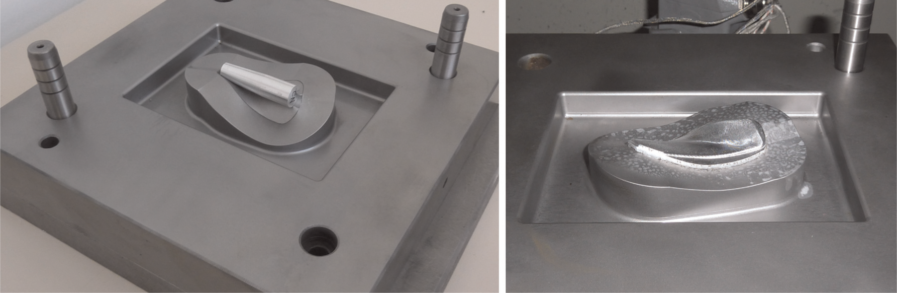
Francis turbine blade forged in the Public University of Navarre from material previously processed by ECAP; (a) before, and (b) after forging. 25
The proposed modelling has been validated experimentally from the FEM simulations of the behaviour of the billets after having undergone upsetting forging. Once the flow rules of AA6063 have been modelled, these have been employed to predict the behaviour of this material, modelling the barrelling that exists in the process and comparing the FEM results with those obtained experimentally. It has been found that there is a high level of agreement between the obtained results, that is to say, the experimental and the FEM results. By means of the development shown in this research work, it is possible to predict the strain and the required force through FEM of parts with complex geometries and with materials that have been previously processed by SPD using angular channel extrusion processes.
Experimental design
The initial material to be analysed is the AA6063 aluminium alloy, which is supplied as cast. In order to have starting material in a recrystallized state, this is first subjected to a heat treatment at a temperature of 415 °C, over 3 h plus one extra hour for the heating slope from room temperature. In all the considered cases, the forging velocity between plane-shape dies is 50 mm/min. The equipment employed is shown in Figure 2, where the temperature controlling system can also be observed. This is done in this way since 50 mm/min is the velocity that will be employed subsequently to manufacture structural components, using this same alloy and in a conventional hydraulic press of 3000 kN belonging to the Public University of Navarre. The billet is maintained between the plane-shape dies during a time of 300 s until it reaches the fixed temperature. Subsequently, the compression is carried out and finally, once the forging force is released, it is left to cool in the air down to room temperature. The different states to be analysed are given below.
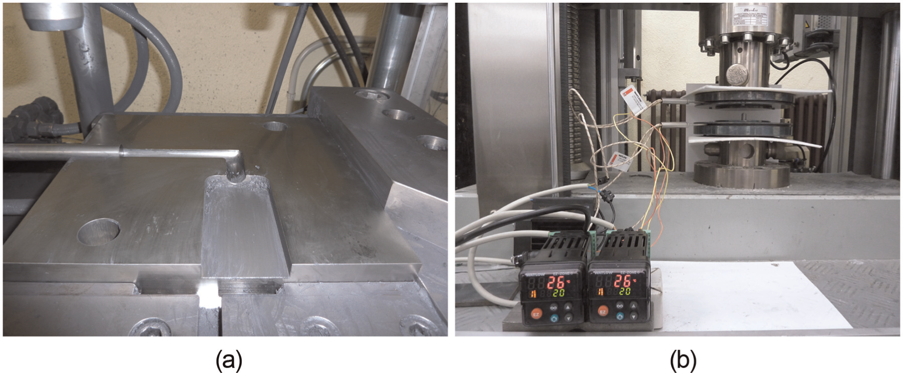
Equal channel angular pressing (ECAP) equipment used in the experiments (a) and plane-shape dies and tooling for the isothermal upsetting (b). 26
First, the standard manufacturing procedure for 6xxx alloys will be analysed (Case 1: forging–quenching–ageing). This case consists in forging from annealed material, followed by processes of quenching and artificial ageing. The conditions used are as follows: the forging is performed at a velocity of 50 mm/min and at temperature values of 25 °C, 125 °C, 200 °C, 275 °C and 350 °C. Later on, a quenching treatment is carried out (1 h and 45 min for the heating slope, 520 °C during 2 h and subsequent cooling in water at 25 °C) followed by an ageing treatment (0.5 h for the heating slope and 175 °C during 12 h).
The second material state to be analysed is as follows: (Case 2: quenching–forging–ageing). The conditions employed are as follows: 1 h and 45 min for the heating slope, 520 °C during 2 h and cooled in water at 25 °C for the quenching, forging at a velocity of 50 mm/min at temperature values of 25 °C, 125 °C, 200 °C, 275 °C and 350 °C and subsequent artificial ageing (0.5 h for the heating slope and 150 °C during 12 h).
Finally, the third state which is analysed is Case 3: quenching–ECAP–forging–ageing. The conditions employed are as follows: 1 h and 45 min for the heating slope, 520 °C during 2 h and cooling into water at 25 °C for the quenching. Later on, an angular channel extrusion was carried out at room temperature and with a velocity of 50 mm/min using the ECAP press belonging to the Public University of Navarre, which is shown in Figure 2. Route C was employed, which consists in rotating the billet 180° in relation to its longitudinal axis. Split dies were used with the following geometry: a diameter of 15 mm, equal radii of 3 mm and an angle between channels of 90°, as can be observed in Figure 3, where these dies are based on the geometry proposed by Luis Pérez. 21 Subsequently, the billets were isothermally forged with a velocity of 50 mm/min at temperature values of 25 °C, 125 °C, 200 °C, 275 °C and 350 °C and, finally, an ageing treatment was applied to them (0.5 h for the heating slope and 125 °C during 12 h).
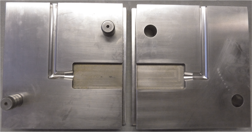
ECAP dies employed in the experiments.
For each of the three above-mentioned cases, the ageing temperature has been taken at a different degree, where this is 175 °C for Case 1, 150 °C for Case 2 and 125 °C for Case 3. The selection of different ageing temperature values for each case is due to the strain state which each billet shows previous to the ageing heat treatment. 11 In Case 1, the accumulated strain is nil due to the quenching heat treatment previously carried out. In Case 2, the billets present a strain value accumulated after the forging process, which is ε = 1.4. In Case 3, all the billets have an accumulated strain value of ε = 2 after having been ECAP processed twice, plus the strain value after the forging (ε = 1.4), giving a total strain value of ε = 3.4. Therefore, the higher the strain value is, the lower the ageing temperature is.
In all cases, cylindrical starting billets with a diameter of 8 mm were employed. They were turned in the case of ECAP from initial material with a diameter of 15 mm so as to have material with a higher degree of deformation homogeneity. The initial height of the billets was 16 mm. The final height at which the upsetting forging between plane-shape dies was performed was 4 mm in all the cases analysed in this research work.
Microhardness values were measured at different locations along the cross-sections of the billets in order to analyse the differences among the distinct states. Moreover, different micrographs in the processed billets were taken with the aim of analysing the final microstructure of the latter. On the other hand, from the study carried out, it was possible to determine the behaviour law of this alloy at different temperature values. In this way, a higher level of accuracy is achieved when analysing the behaviour of more complex geometries, such as that shown in Figure 1.
Analysis of mechanical properties
In the present section, the results corresponding to the measurement of microhardness and experimental compression curves are shown for the three starting states under consideration.
Microhardness
In order to analyse the variation in the mechanical properties, 25 microhardness measurements were taken in each of the samples and in an equispaced manner. The microhardness values along with the locations at which they have been taken may be observed in Tables 1–3. From the microhardness measurements that are shown in Tables 1–3, the graphs depicted in Figures 4–6 are generated.
Microhardness (HV) for AA6063 (Case 1: annealing + forging + quenching + ageing).
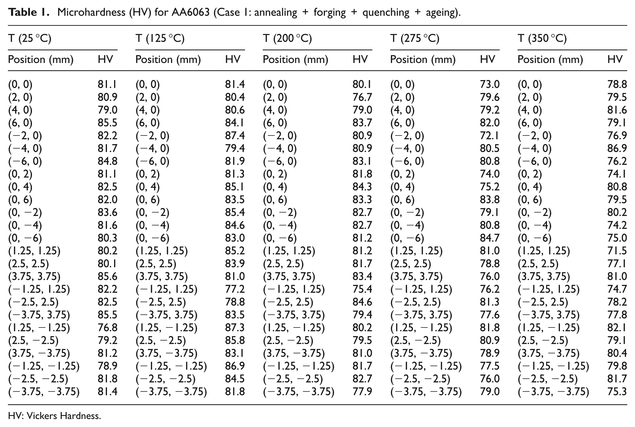
HV: Vickers Hardness.
Microhardness (HV) for AA6063 (Case 2: annealing + quenching + forging + ageing).
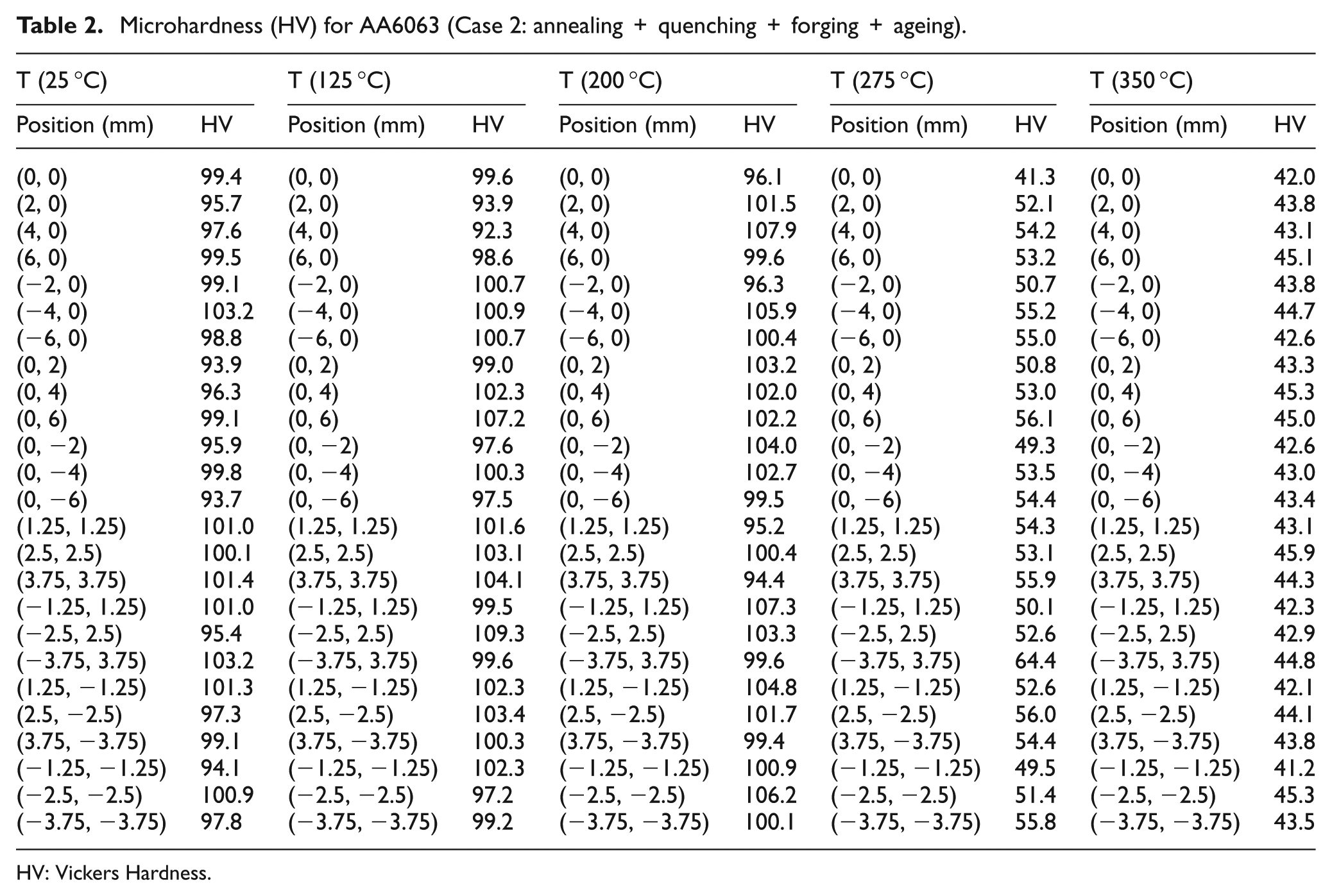
HV: Vickers Hardness.
Microhardness (HV) for AA6063 (Case 3: annealing + quenching + ECAP + forging + ageing).
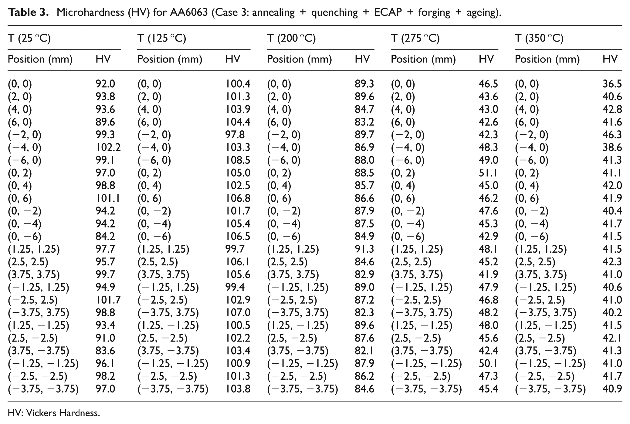
HV: Vickers Hardness.
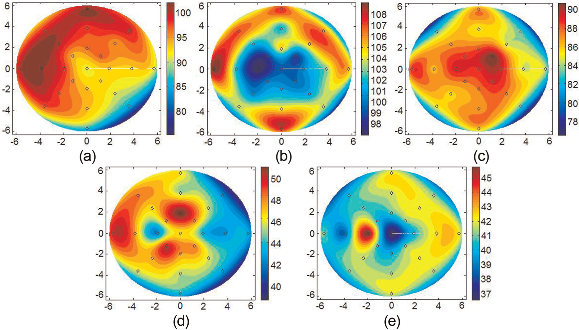
AA6063 (Case 1: annealing + forging + quenching + ageing): (a) 25 °C, (b) 125 °C, (c) 200 °C, (d) 275 °C and (e) 350 °C.
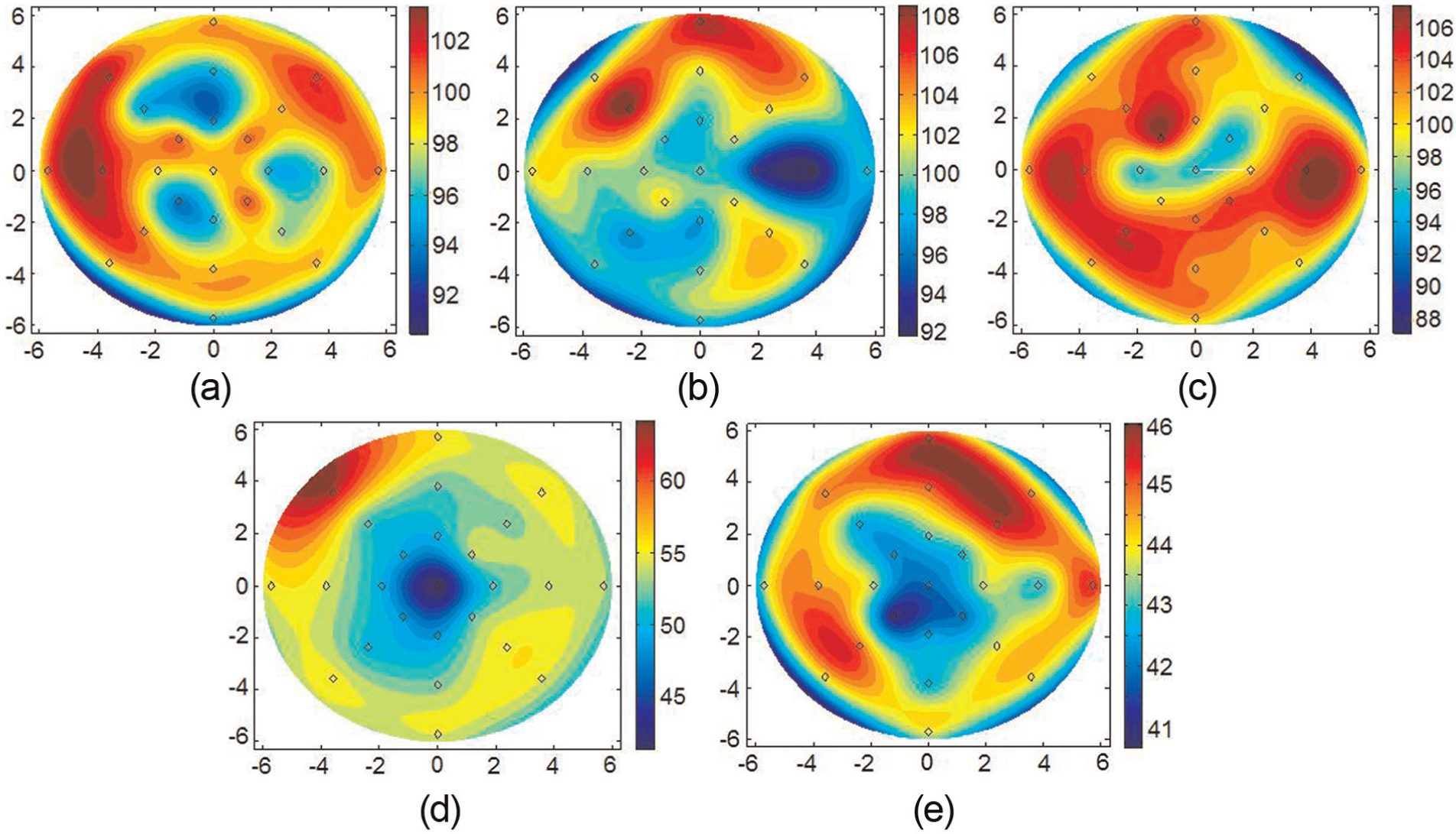
AA6063 (Case 2: annealing + quenching + forging + ageing): (a) 25 °C, (b) 125 °C, (c) 200 °C, (d) 275 °C and (e) 350 °C.
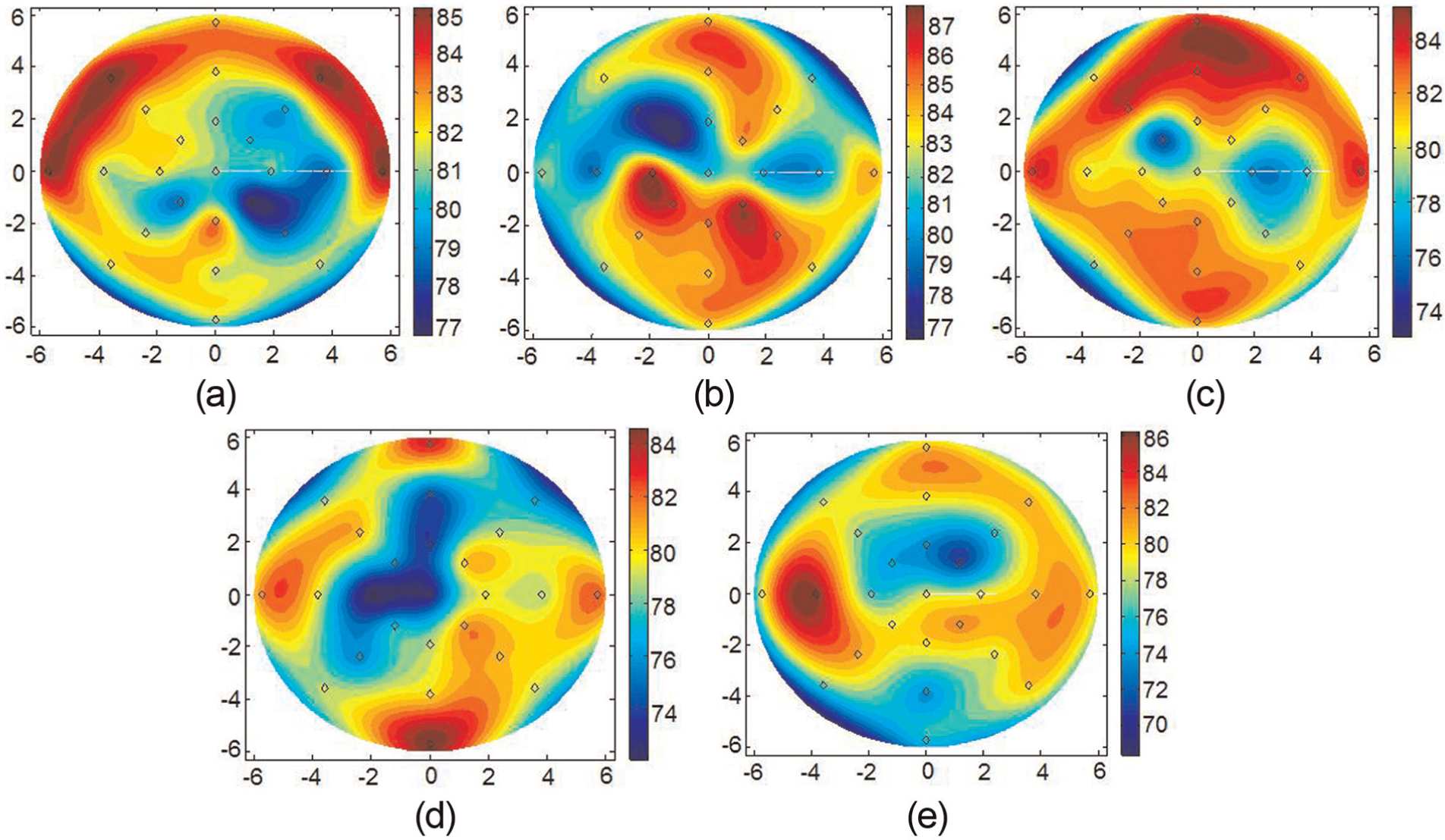
AA6063 (Case 3: annealing + quenching + ECAP + forging + ageing): (a) 25 °C, (b) 125 °C, (c) 200 °C, (d) 275 °C and (e) 350 °C.
From the previous microhardness values, graphs expressed in polar coordinates have been generated using the software MATLAB™. So as to attain Figures 4–6, 25 positions have been used (eight different angle values × three distinct radius values plus the central point at the centre of the circumference) where microhardness values are known, and in this way, a total of 301 positions have been interpolated (100 different angle values × 30 distinct radius values plus the central point at the centre of the circumference). Figure 7 shows the mean and the standard deviation values of these microhardness measurements, respectively.
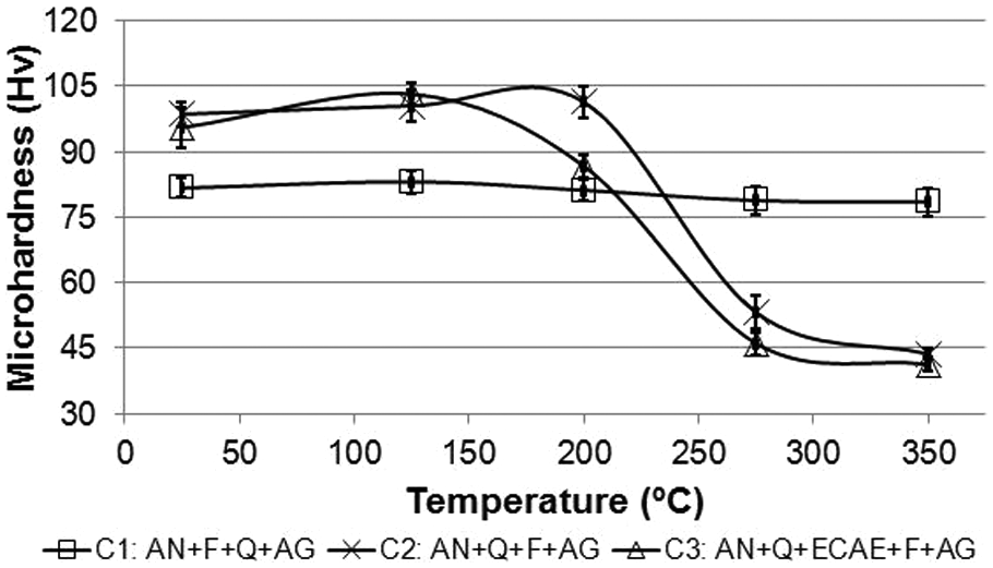
Mean and standard deviation values of microhardness in the AA6063 billets.
As can be observed in Figure 7, in the temperature range between 25 °C and 125 °C, the values obtained by the manufacturing method named as Case 2 (annealing, forging, quenching and ageing) are similar to those obtained after having been ECAP processed and subsequent artificial ageing (Case 3). However, it should be pointed out that a higher variability has been found in the parts processed by ECAP, as is shown in Figure 7, which may be explained by the higher value of anisotropy that the microstructure presents, as a consequence of the deformation pattern imparted by SPD. On the other hand, there is an effect related to the temperature at which ageing has been carried out, thus producing a recovery in the billet processed by ECAP, as a consequence of the high value of accumulated strain due to the fact that it has been ECAP processed twice (ε = 2). It can be observed in Figure 8 that at the processing temperature (25 °C) and previous to the ageing heat treatment, the billet processed by ECAP presents a much higher value of mechanical strength than those that have not been ECAP processed. Therefore, it is likely that the stress relief caused by the ageing treatment leads to a reduction in the hardness increase, as a consequence of the ECAP process, and that this could be expected after ageing. In the same way, the existence of a highly deformed microstructure can cause the appearance of precipitates at the grain borders and it is possible that due to this fact, a growth in the precipitates is produced at the ageing temperature since this effect is higher at the grain borders, which agrees with that stated by Humphreys and Hatherly. 27
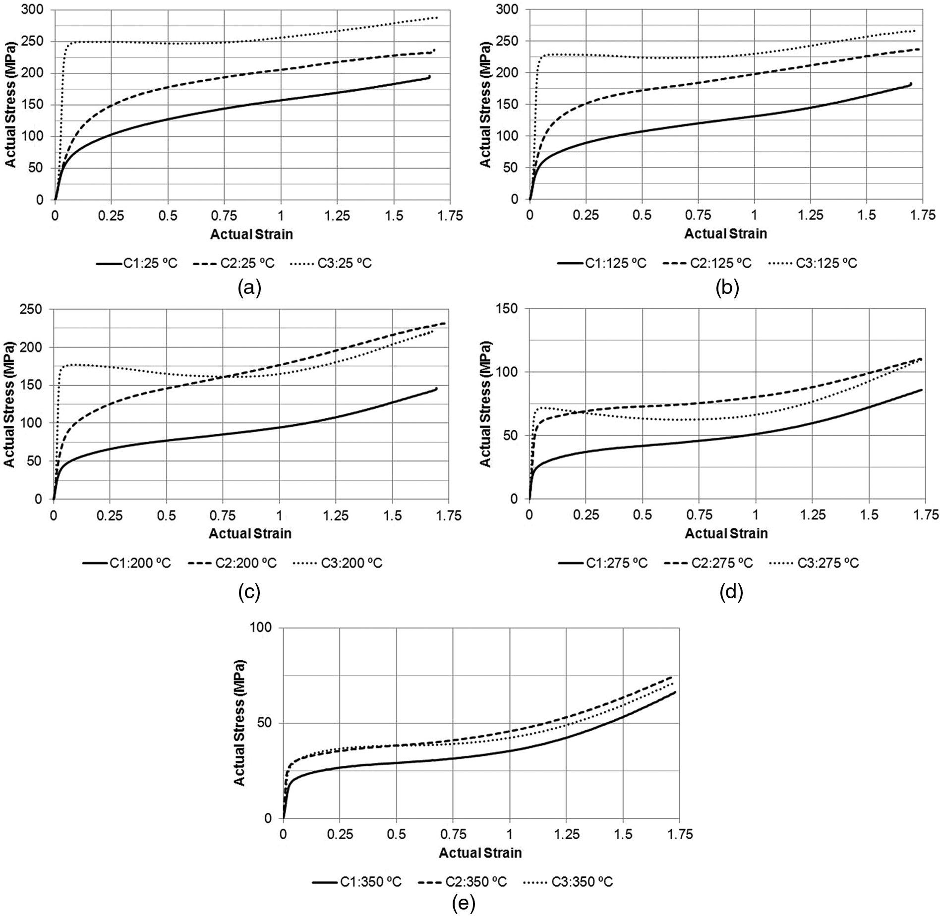
Flow stress during the upsetting process at 25 °C–350 °C (experimental results); (a) cases 1, 2 and 3 at 25 °C, (b) at 125 °C, (c) at 200 °C, (d) at 275 °C, and (e) at 350 °C.
In the range of temperature values between 125 °C and 225 °C, there is a similar behaviour to that observed at the temperature of 25 °C, for the material states named as Cases 2 and 3. Nevertheless, in this case, the difference in the mechanical strength increase is lower than that observed in the previous case. It is possible that in this temperature interval, a growth in subgrains is produced, that is to say, a recovery process by subgrain growth.
As forging temperature is increased, the softening effect is much higher in the billets processed by ECAP, which may be explained by the fact that there exists a higher value of accumulated cold deformation since they have been ECAP processed twice with route C. Finally, in the temperature range varying from 275 °C to 350 °C, a higher softening is obtained in the billets that have been processed by ECAP, which may be justified by the fact that a higher deformation value in the ECAP-processed billets leads to a recrystallization phenomenon in the material and thus to its subsequent softening. In this zone, material recrystallization is produced, with a finer microstructure in the case of the billets that have been ECAP processed, as a consequence of the higher value of accumulated plastic strain. The above-mentioned effects are favoured by the fact that the material stays during 5 min between the plane-shape dies with the aim of reaching the temperature at which the isothermal forging is going to be carried out. Subsequently, the forging process lasts approximately 18 s, where there now exists a slight increase in the temperature as a consequence of the plastic deformation process. The higher this increase is, the lower the forging temperature is, because of convection.
Regarding the variability achieved in the forged billets, it can be observed that those processed by ECAP present a higher homogeneity at room temperature and at high temperature values, rather than those forged from other starting states, with the exception of the temperature point corresponding to 125 °C, at which there is a higher degree of variability. This may be explained because of the fact that a non-homogeneous recovery exists in the ECAP-processed billet, owing to the anisotropy inherent in the SPD process itself.
Moreover, it can be observed that the hardness values obtained in Cases 2 and 3 are higher than those obtained with the traditional manufacturing method (Case 1) for temperature ranges varying between 25 °C and 225 °C. This tendency is just the opposite for higher temperature ranges (275 °C–350 °C), as a consequence of the recrystallization undergone in the case of the alloys that present accumulation of plastic deformation.
Flow stress measurements
As well as the microhardness study, experimental curves corresponding to the flow of the materials were determined during the upsetting process, as can be observed in Figure 8. In Case 3, three different zones can be clearly observed. The first of them (Zone I) corresponds to the elastic part, the second reaches up to a true strain of, approximately, ε = 0.6 (Zone II), depending on the temperature, and the third one (Zone III), in which the barrelling effect appears due to the compression the material undergoes between the plane-shape, dies. In addition, at a lower temperature than 200 °C, Case 3 requires a higher force value for the billet to be deformed, due to the increase in the mechanical strength introduced by the plastic strain accumulated during the ECAP process. At higher temperature values, it may be observed that after the material recrystallization takes place, the flow curve is relatively similar to that in Case 2, where this is practically the same at the temperature of 350 °C, when the material is completely recrystallized and there is grain growth. Between Cases 1 and 2, the behaviour of curves is quite similar and they grow throughout all the forging of the billets, while this is not possible to observe in Zone II. This is because of the fact that the material does not have any initial plastic strain. In Case 3, this does not occur because the material has been previously deformed by ECAP (ε = 2), and thus, the material is practically saturated in strain, which implies that Zone II is flat. For this third case study, as the forging temperature increases, recrystallization takes place, and therefore, a drop in the curve stress is observed in Zone II.
Once the flow curves of the distinct tests have been experimentally determined, the objective is to determine a flow rule up to much higher strain values, such as ε = 2.5, in order to be able to employ these flow rules in the FEM simulations and thus to achieve higher accuracy in the results. To do so, and with the aim of interpolating the flow stress values of the material up to higher deformation values (ε = 2.5), neural networks are employed from experimental deformation data obtained in the plastic zone, that is to say, previous to the barrelling effect (ε = 0.6).
Subsequently, FEM of compression between plane-shape dies are performed in order to validate the flow curve obtained through this procedure. In order to do this, load–stroke curves obtained once the barrelling effect appears will be compared with those predicted by finite element using the flow rules obtained with ANNs. It may be pointed out that it will be necessary to adjust the friction coefficient existing between the dies and the part. For this reason, different friction coefficient values will be simulated and the most adequate will be selected. Moreover, this research work provides an estimate of the friction coefficient to use in function of the temperature.
Modelling
As is well known, for FEM, the material behaviour law is required. This has been done in other previously published research works from the tension or compression flow stress curves fitted with laws of type Hollomon or Voce, among others. Nevertheless, given that in these tests, the true strains obtained, before the material failure occurs, are not very high, it means that there are no fittings good enough to predict the material behaviour except in the case where much higher deformation values are attained, as for example those that can appear in SPD processes, as is the case of ECAP or forging processes. Therefore, the behaviour law of the material will be determined by means of neuronal networks for each temperature value of Case 3, where the equations obtained will be of type σ = σ(ε, T).
Determination of the flow stress using artificial neuronal networks
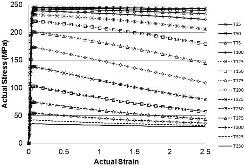
In this research work, neural networks are used with the aim of predicting the material behaviour up to strain values of ε = 2.5. Flow stress curves of the material in the plastic zone (compression) are used as a basis up to values of approximately ε = 0.6, depending on the deformation case. Figure 9 shows flow rules once they have been fitted by means of neural networks.
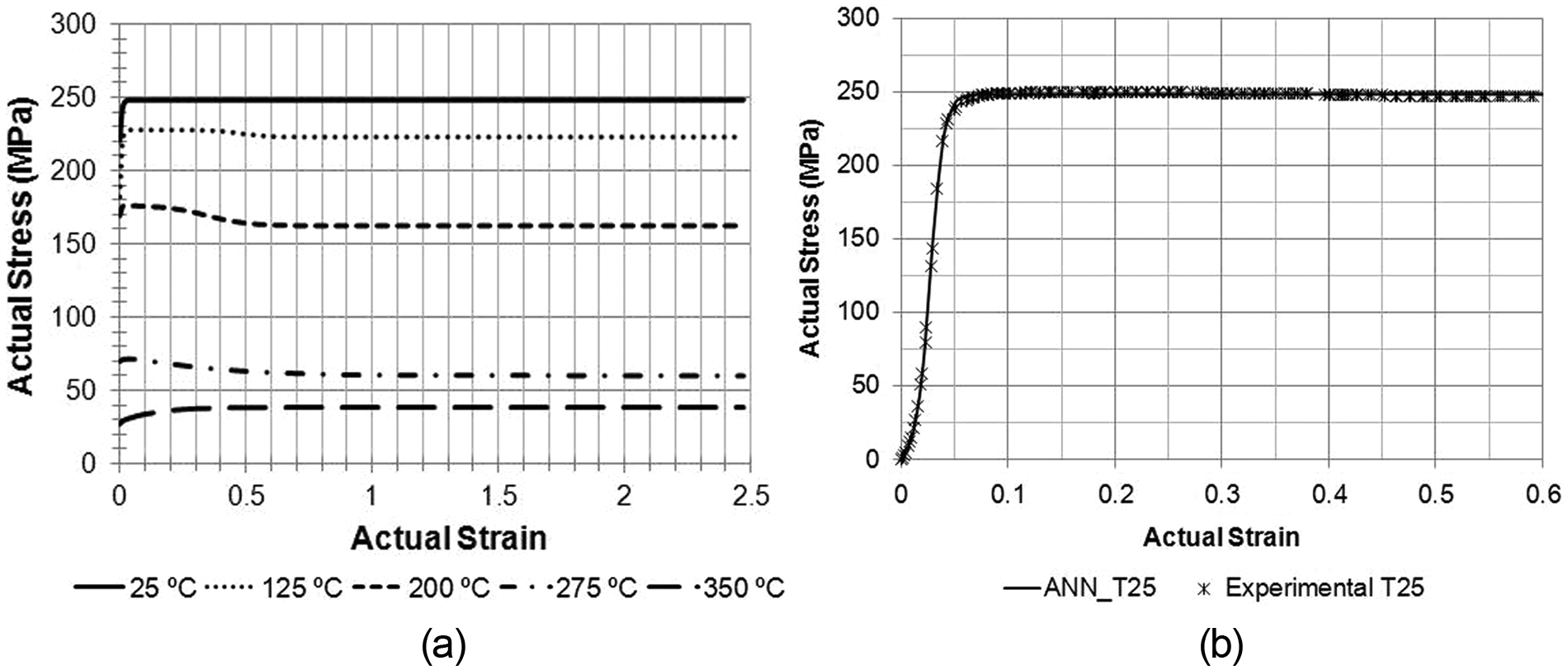
Flow stress at the experimental temperatures using artificial neural networks (a) and comparison of flow stress between experimental values and those from neural network (b).
The flow stress curves shown in Figure 9 were obtained taking one neural network into consideration for each temperature. This modelling has the advantage of being more precise in respect to that obtained with the use of one single neural network for the whole set of temperatures, and hence, a single neural network was employed for each test temperature since the aim was to determine σ = f(ε, T = constant), that is, as has been previously said, one network for each test temperature as a previous step for assessing σ = f(ε, T). The values obtained from interpolating by means of neural networks can be seen in Figure 9. This was carried out in this way given that more precision is desired in the simulations.
The ANNs employed in this study were made up of an input layer, a hidden layer and an output layer. The results found in this study have been obtained using the Neural Network Toolbox™ of MATLAB™ (R2012b). Experimental compression results (from ε = 0 to ε = 0.6) previously shown in Figure 8 were used to train each network in order to obtain the flow stress for values of deformation from ε = 0 to ε = 2.5 afterwards. A Levenberg–Marquardt algorithm was used to train the neural networks. Moreover, a pure linear function was used for the output layer and a log-sigmoid function was used as transfer function for the hidden layer. In Figure 9, it can be observed that there exists a good approach to the true material behaviour when using flow rules assessed by neural networks. In particular, the plotted values are for the case of room temperature (25 °C). A similar behaviour has been attained for the rest of the considered temperature values in this study. It should be stressed that the neural network will be employed to predict not only the data in the range that can be experimentally determined (up to ε = 0.6) but also the stress–strain values up to much higher values (ε = 2.5).
In spite of not having values corresponding to the material flow stress for these deformation values, as will be shown below, by means of the use of neural network, it has been possible to determine this curve to a high level of accuracy. This has been validated by FEM and by making a comparison with the experimental data that are known when performing the isothermal forging at different temperatures. In particular, the barrelling effect, which takes place during the material compression, has been modelled and the experimental curves have been compared with those provided by finite element. As will be shown below, there is a high level of agreement between the results, which allows us to state that the approaches carried out are correct. It can also be stated that the proposed approach presents more advantages when we work with alloys having a high value of mechanical strength and a low value of ductility, due to the difficulty in obtaining flow curves up to similar values to those under consideration in this research work (ε = 2.5).
In order to have flow rules at different temperature values from the experimental ones, a single neural network will be employed, which is going to be trained with stress and strain values arising from the five experimentally tested temperature values. From these values, a model predicting σ = f(ε, T) is generated, as shown in Figure 10. In this case, the performance of the ANN by statistical analysis of the error and the regression results using the ANN (shown in Figure 10) are shown in Figure 11, where it can be observed that the ANN employed in this case is made up of an input layer, one hidden layer and an output layer, where f1 is a log-sigmoid function and f2 is pure linear (Table 4). Then, σ = f(ε, T) can then be obtained from equation (1).
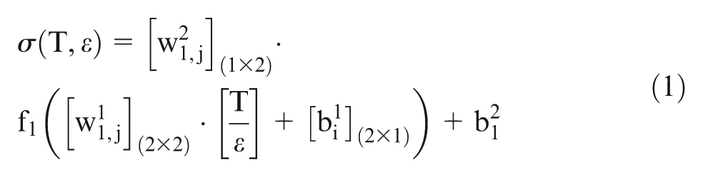
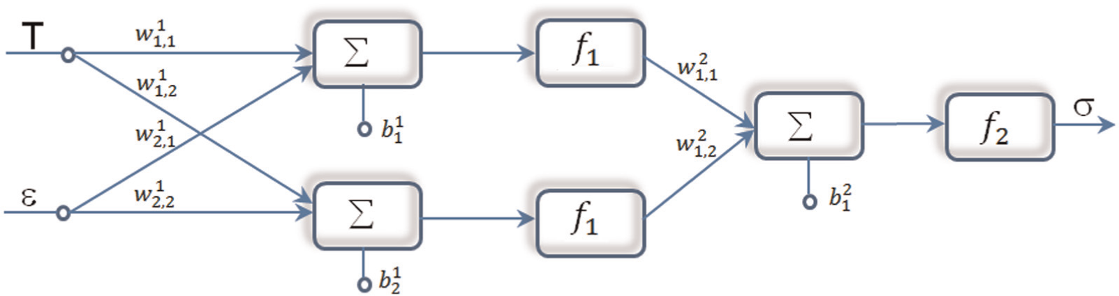
ANN configuration for predicting σ = f(T, ε).
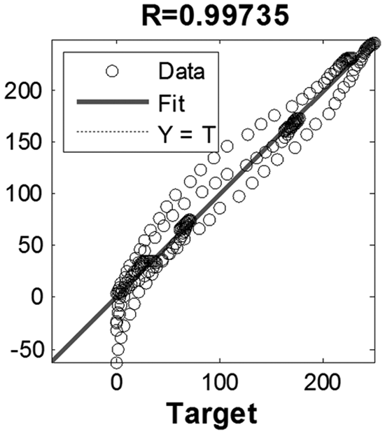
Regression results.
Network parameters.
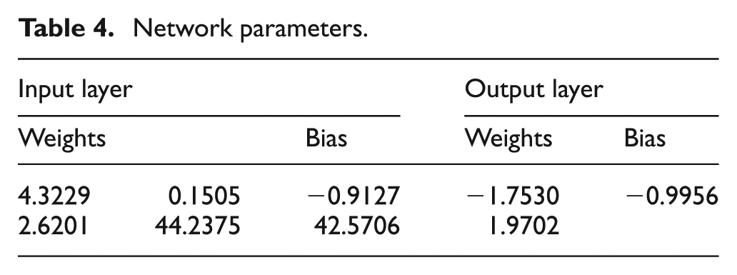
Figure 12 shows the results predicted by the neural network shown in Figure 10. As can be observed, they agree with the results obtained when fitting a single neural network for each of the upsetting tests in which experimental data were known. This second approach presents the advantage of being able to have flow rules for AA6063 at temperature values different from those used in the tests.
σ = σ(ε, T) using artificial neural networks.
It may be pointed out that it is possible to increase the accuracy of the results obtained with a single neural network in order to model the behaviour σ = σ(ε, T) from an approximated knowledge of the forging temperatures. This can be done in such a way that instead of interpolating in all the temperature range (25 °C–350 °C), the approach is divided into several work temperature ranges.
FEM simulations
FEM MSC.Marc™ software was employed in order to analyse the isothermal upsetting of the AA6063. The flow stress curves obtained using ANNs were employed with the aim of modelling the behaviour of the AA6063 aluminium alloy, as accurately as possible, up to actual strain values of ε = 2.5. In this section, the results obtained from the FEM simulations are shown. Moreover, the thus-obtained results, based on employing flow stress curves obtained using ANNs, are compared with those obtained from the experimental tests.
As was previously mentioned, 16 mm length and 8 mm diameter billets of AA6063 were employed in the upsetting experiments. Therefore, this will be the geometry, which is to be considered in the FEM simulations. These simulations were carried out taking rotational symmetry into account, which will allow for a significant reduction in the calculation time to be obtained. In all the simulations performed, the rotational symmetry is obtained around the x-axis. The dies have been modelled with a radius of 75 mm and with a width of 20 mm, which corresponds to the actual dies employed in the experiments. The starting 2D-element size was a square of 0.25 mm edge. The dies were meshed using the automatic mesh option with two different types of sizes. A fine meshing using 2D elements of 0.20 mm edge was employed for the contact zones between both billet and dies, and a wider meshing of 1 mm edge was employed for the rest of the volume of the die. Figure 13 shows the mesh of the billet and the dies as well as the boundary conditions employed in order to carry out the simulations.
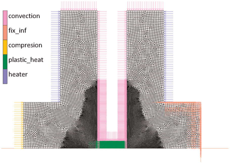
Die and billet mesh and boundary conditions.
As was previously mentioned, all the FEM simulations were carried out using the flow stress curves of the AA6063, obtained from upsetting tests at different temperatures and using ANNs in order to model the behaviour of this aluminium alloy up to strains of ε = 2.5. An isotropic material with a Young modulus of 70 GPa and a Poisson coefficient of 0.3 was employed. The process speed was 50 mm/min (0.833 mm/s). The time for performing the simulations was 16.8 s, which corresponds with the time required for upsetting the billet from the initial length to its final shape.
The attained experimental results were used in order to compare the actual values of the load with those provided by FEM, where the flow stress curves used are based on ANNs. With respect to the temperature boundary conditions, a non-forced natural convection is attained in the whole outer surface of the dies with a convection coefficient of 5 W/m2 K and with a room temperature of 25 °C. Moreover, the heat generation is considered. This is performed using electrical resistances, which are placed in the lower part of the dies. These resistances are capable of generating a heating power of 3 W/mm2 and they are employed in order to keep a constant temperature in the dies during the upsetting process. Finally, it has been taken into consideration that 90% of the attained deformation energy is transformed into heat.
It is important to state that the friction coefficient, which exists in the isothermal upsetting process, should be determined. Therefore, different FEM simulations were previously carried out by varying the friction coefficient, as shown in Figure 14. It can be observed that using the flow stress curve based on employing ANNs, it is possible to accurately predict the behaviour of this aluminium alloy in the upsetting process (Figure 15). Different friction coefficients, which employ the Shear model, 28 were used. It was determined that for the temperature range from 25 °C to 125 °C, m = 0.3 is the friction coefficient, which best fits the experimental load results. From 125 °C to 200 °C, it was determined that m = 0.4 corresponds to the most accurate results and, for higher temperature values, a friction coefficient of m = 0.9 was employed, because of the higher adherence between billet and dies. Figure 14 shows a comparison between experimental and simulation results for the load–stroke curves at the different processing temperatures.
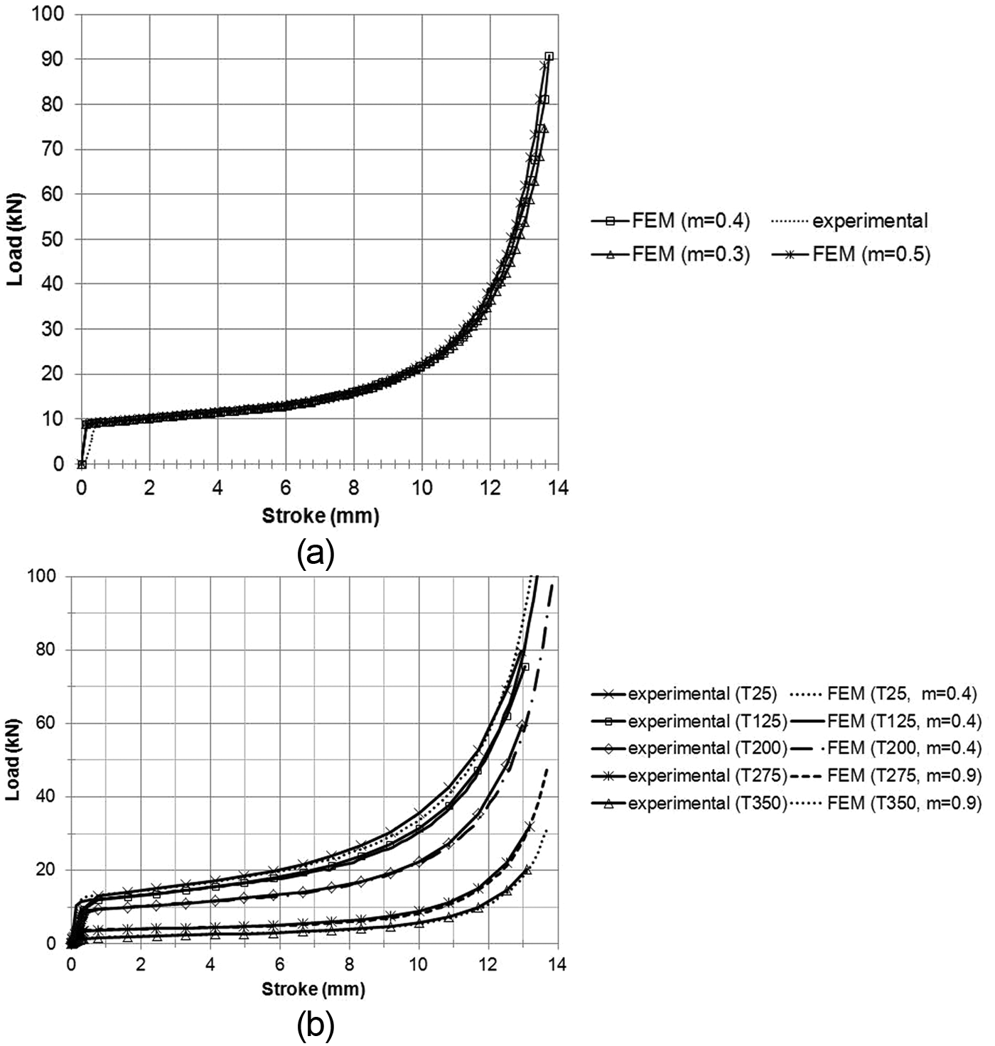
Flow stress during the upsetting process at 200 °C, considering different friction coefficients (Shear model). Comparison between FEM and experimental results (a) and flow stress during the upsetting process at different temperatures and with shear friction coefficients that best fit experimental results (b).
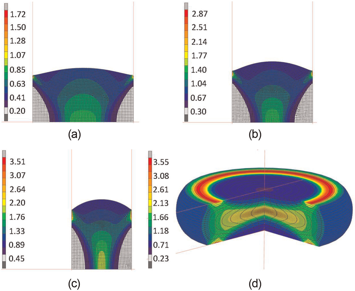
Total equivalent plastic strain at different upsetting stages: (a) total equivalent plastic strain at 10 mm, (b) total equivalent plastic strain at 8 mm, (c) total equivalent plastic strain at 6 mm and (d) total equivalent plastic strain at 4 mm.
Figure 16 shows a downward trend in the Von Mises stress from the centre to the external part of the dies. Moreover, Figure 16 shows that the higher the upsetting temperature is, the lower the Von Mises stress obtained is.
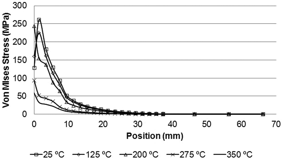
Von Mises stress distribution from the centre (0 mm) to the external part of the dies (75 mm).
Figure 17 shows the Von Mises stress at different stages of the upsetting process for the case of 200 °C.
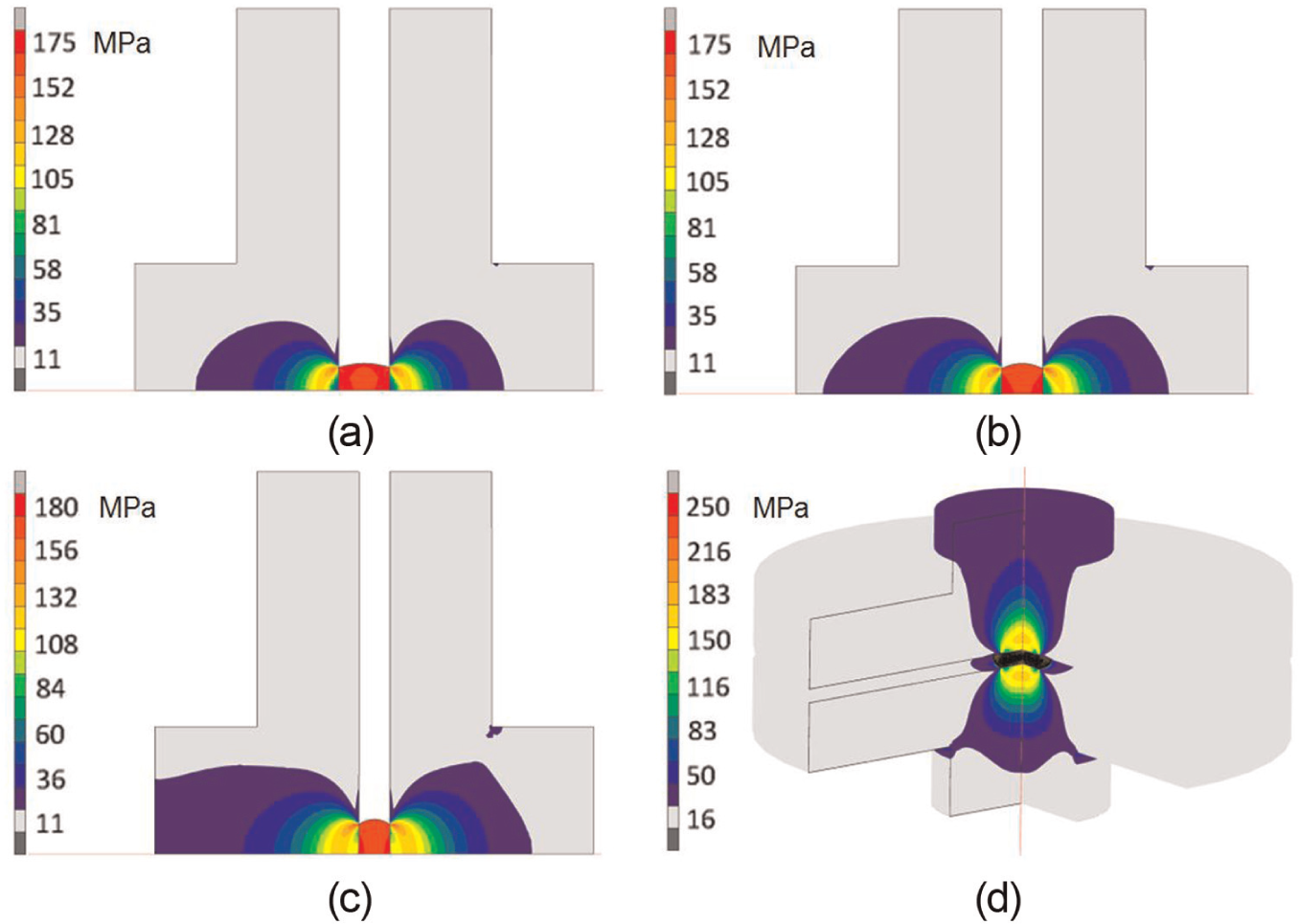
Von Mises stress at different stages of the upsetting process for the case of 200 °C: (a) Von Mises stress at 10 mm, (b) Von Mises stress at 8 mm, (c) Von Mises stress at 6 mm and (d) Von Mises stress at 4 mm.
As previously mentioned, the billets are kept between the plane-shaped billets for 300 s in order to assure that the required temperature is reached inside the billet. Then, the upsetting process is carried out and, finally, once the load is released, the billets are cooled down to room temperature. These experimental conditions were simulated by FEM. Figure 18 shows the temperature distribution obtained in the isothermal upsetting at 200 °C along with the initial heating of both billet and dies. This initial heating was obtained after 5 min so as to reach the forging temperature of 200 °C.
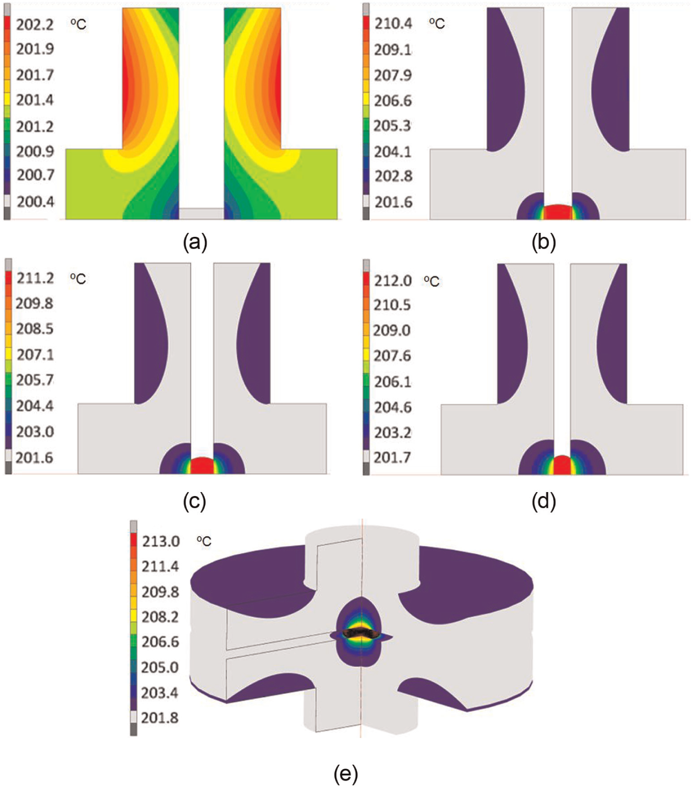
Temperature distribution in both billet and dies at 200 °C for different processing stages of the isothermal upsetting of an AA6063: (a) initial heating of billet and dies, (b) temperature at 10 mm, (c) temperature at 8 mm, (d) temperature at 6 mm and (e) temperature at 4 mm.
Figure 19 shows the temperature increase during the isothermal upsetting of the AA6063. The starting time of 300 s corresponds with the values attained after 5 min heating in order to reach the die temperature. These values correspond with those predicted by FEM and ΔTemperature is given by (T − Tforging), where T is the temperature predicted by FEM and Tforging is either of the following temperatures: 25 °C, 125 °C, 200 °C, 275 °C or 350 °C, which correspond with the experimental conditions. Moreover, the evolution of the temperature during the first 300 s is also shown in Figure 19 for the case of 25 °C.
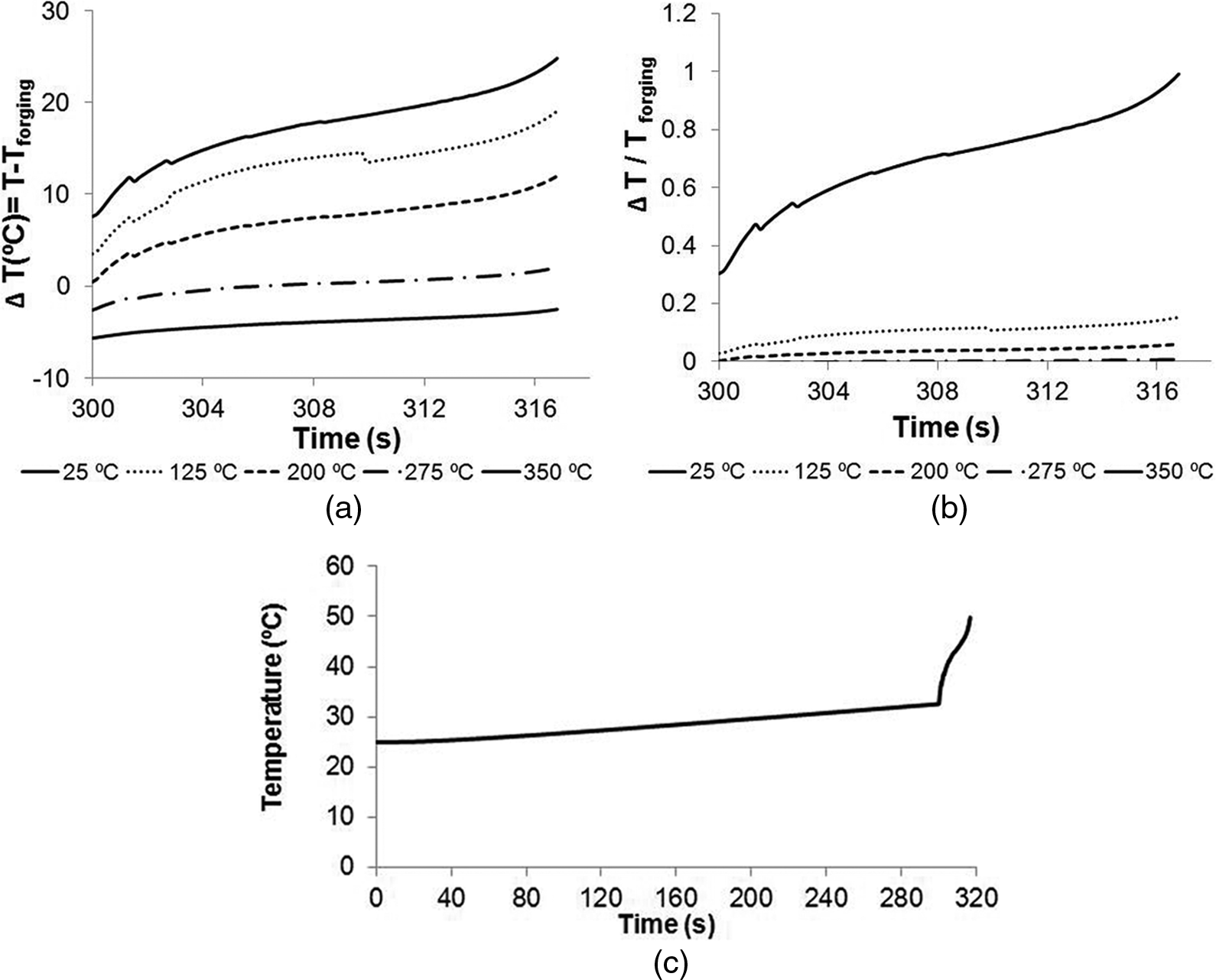
Temperature increase, expressed in degree Celsius, during the isothermal upsetting of AA6063; (a) T-Tforging, (b) (T-Tforging)/Tforging, and (c) temperature evolution in the case at 25 °C.
As Figure 19 shows, the temperature of 25 °C displays the highest increase at its final temperature, which is a consequence of the strain hardening. The rest of the analysed temperatures undergo a lower increase compared to that obtained in the case of 25 °C. In any case, it is likely that both the initial 5 min heating as well as the increase in the temperature during the isothermal upsetting may have a certain amount of influence in the final microstructure of the thus-processed billets and so a stress relief may be obtained.
Conclusion
In this research study, a comparative analysis on the mechanical properties of AA6063 has been carried out after having been processed by isothermal upsetting using plane-shape dies and starting from different initial deformation states. It has been found that within the temperature range between 25 °C and 125 °C, the values obtained by the manufacturing method named as Case 2 (annealing, forging, quenching and ageing) are similar to those obtained after ECAP and subsequent artificial ageing (Case 3). However, it should be pointed out that a higher variability has been found in the parts processed by ECAP, which may be explained by the higher value of anisotropy that the microstructure presents as a consequence of the deformation pattern imparted by SPD. On the other hand, there is an additional effect related to the temperature at which ageing has been carried out, thus producing a recovery in the billet processed by ECAP. This is because of the high value of accumulated strain due to the fact that it has been ECAP processed twice (ε = 2). Therefore, it is likely that the stress relief caused by the ageing treatment will lead to a reduction in the hardness increase, as a consequence of the ECAP process, and that this could be expected after ageing.
As forging temperature is increased, the softening effect is much higher in the billets processed by ECAP, which may be explained by the fact that there exists a higher value of strain hardening since they have been ECAP processed twice with route C. Finally, in the temperature range varying from 275 °C to 350 °C, a higher softening is obtained in the billets that have been processed by ECAP, which may be justified by the fact that a higher deformation value in the ECAP-processed billets leads to a recrystallization phenomenon in the material and thus to its subsequent softening. Moreover, the flow stress curves of a 6063 aluminium alloy processed by ECAP have been determined, taking the temperature into account using ANNs.
It has been demonstrated, by means of comparison with experimental results, that it is possible to achieve a high degree of accuracy in the FEM simulations. It has also been shown that by combining experimental tests with ANNs, it is possible not only to accurately predict the flow stress curves up to deformations much higher than those obtained in the compression tests but also to obtain high accuracy in more complex FEM simulations. With this research work, it is possible to employ these flow stress curves in order to carry out more complex simulations and in order to obtain higher accuracy in FEM simulations than the accuracy obtained using traditional fitting methods of flow rules.
Footnotes
Declaration of conflicting interests
The authors declare that there is no conflict of interest.
Funding
The authors would like to acknowledge the support given by the former Spanish Ministry of Science and Innovation (now Ministry of Economy and Competitiveness) under the research project DPI2010-18941.