
Abstract
In this study, a simple two-dimensional measurement system based on optical design was developed to measure the motion errors of the linear guideway. Compared with the transitional methods about the linear guideway for measuring the motion errors, our proposed two-dimensional optical measurement system can simultaneously measure horizontal and vertical running straightness errors for the linear guideway. Calibration results showed that the residual error of the two-dimensional optical measurement system is less than 0.5 µm. Measurement results showed that the three tests for the motion errors of the linear guideway are almost coincident with the laser interferometer within 1000 mm. The standard deviations of the horizontal and vertical straightness measurement systems are 0.9 and 1.2 µm.
Keywords
Introduction
Linear guideways are an important element in precision machinery, which is widely used in the automation, power transport, semiconductor, medical, and aerospace industries. The running accuracy of linear guideways is divided into five classes, namely, normal grade (N), precision (P), high precision (H), super precision (SP), and ultraprecision (UP). Measurement systems for linear guideways are divided into contact and noncontact types. Contact-type systems use a linear variable differential transformer (LVDT) and a dial gauge to measure N-, H-, and P-grade linear guideways. Noncontact-type systems use an autocollimator and a laser interferometer to measure SP- and UP-grade linear guideways. An LVDT or a dial gauge is often used to measure motion errors of linear guideways because laser interferometers are costly. In the general measurement method, a contact-type system is used to measure the motion error between the base level of the measuring platform and the carriage. The accuracy of the measurement results is affected by the base level of the measuring platform. The method uses manual manipulation and is time-consuming. Therefore, an H measurement system for simultaneously measuring the straightness errors of linear guideways is required.
In recent years, many researches based on special system design have been proposed for simultaneously measuring multi-degree-of-freedom (DOF) motion errors.1,2 Lee et al. 3 presented a two-dimensional (2D) optical measurement system that uses a laser beam, beam splitters (BSs), a reflector, and quadrant detectors (QDs). The resolutions of the system are 0.048 arcsec and 26 nm. Kim et al. 4 presented a multidimensional motion measurement system that comprises a grating, three lenses, and detectors. A displacement of 6 DOFs can be obtained. The resolutions of the system are 0.0133 arcsec and 60 nm. Fan et al. 5 used a DVD pickup heads to develop an H straightness measurement system. Their system has a measurement range of 200 mm and an accuracy of 0.6 m. Liu and Jywe 6 presented a 4-DOF measurement system composed of a grating, two lenses, and detectors. The resolution of the system is 100 nm. Jywe and colleagues 7 presented a multidimensional motion measurement system that comprises an interferometer, two corner cubes (CCs), and three QDs. A linear displacement and angular displacement of 6 DOFs can be obtained. The resolution of the system is 25 nm and 0.06 arcsec. Liu et al. 8 designed an optical path for an H straightness measurement system with four CCs. The measurement system can measure 2D errors and its accuracy is 0.5 µm. Chen et al. 9 presented a three-dimensional vibration measurement system with CCs and QDs; position errors can be obtained. The resolutions of the system are 100 nm and 1000 Hz. Hsieh et al. 10 designed an optical vibrometer based on multi-DOF measurement. The accuracy of the proposed optical vibrometer is ±30 nm/200 nm and ±0.04 arcsec/0.1 arcsec at 1000 Hz. Liu and Cheng 11 proposed a multi-DOF laser encoder that can simultaneously measure straightness, angular, and linear motion error. The accuracy of the system is ±0.6 µm for straightness, ±0.8 arcsec for angular error, and ±1.2 µm for linear displacement.
In this study, a 2D optical measurement system that uses multiple optical paths to simultaneously measure the horizontal and vertical straightness of linear guideways is proposed. The 2D optical measurement system comprises two collimated laser beams, two BSs, two CCs, and two QDs. The 2D optical measurement system is set up on the precision linear positioning stage to automatically measure the running accuracy of linear guideways. The 2D optical measurement system has three main advantages: (1) it can be used to simultaneously measure the horizontal and vertical straightness of linear guideways; (2) it is a sample 2D optical measurement system, and (3) it has a high resolution.
System structure and measurement principle
Overall system layout
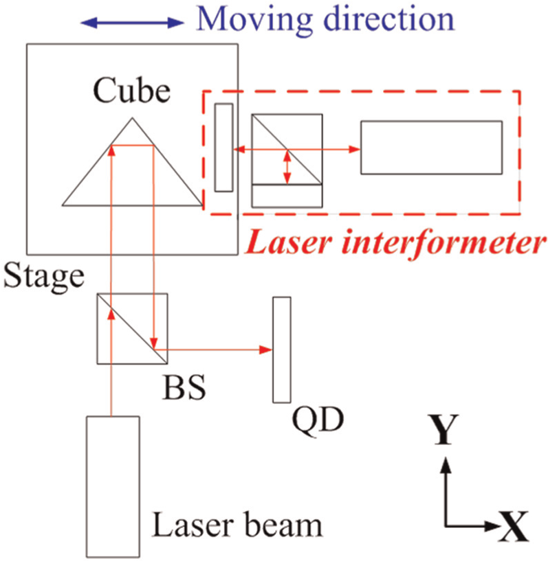
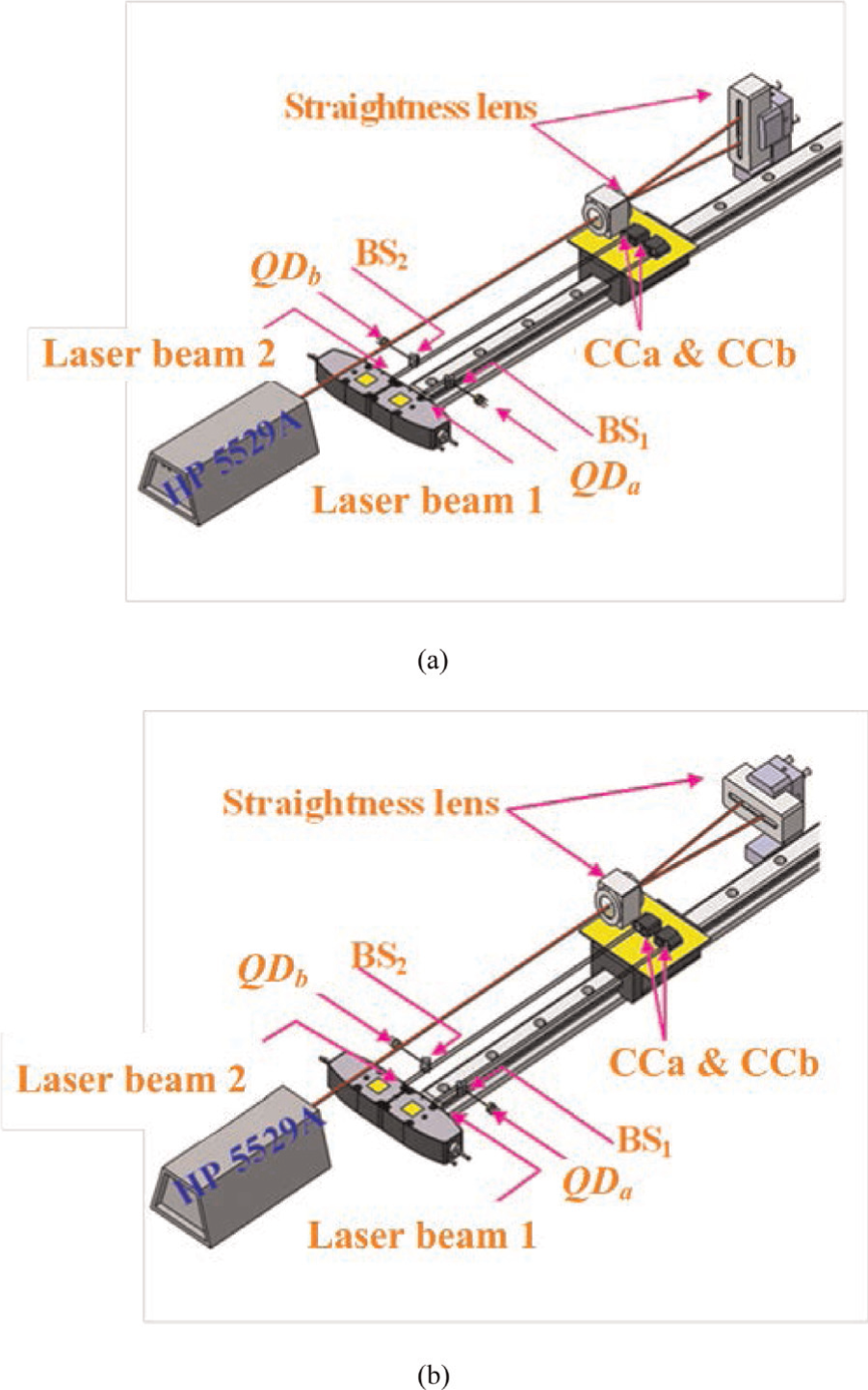
The proposed 2D optical measurement system is set up on the precision linear positioning stage for measuring the motion errors of the linear guideway, as shown in Figure 1. The precision linear positioning stage integrates a precision granite table, a movable gantry stage, and a linear motor. The linear motor is the main linear driving system and is configured to drive a carriage, whose motion is automatically measured via an optical measurement system and a user interface. The component specifications of the precision linear positioning stage are shown in Table 1. The development of the man–machine interface primarily involves hardware and software integration of the precision linear positioning stage for linear guideways and the development of an operation interface; the interface allows the precision linear positioning stage to be easily operated, to perform automatic measurement, and to process data rapidly.
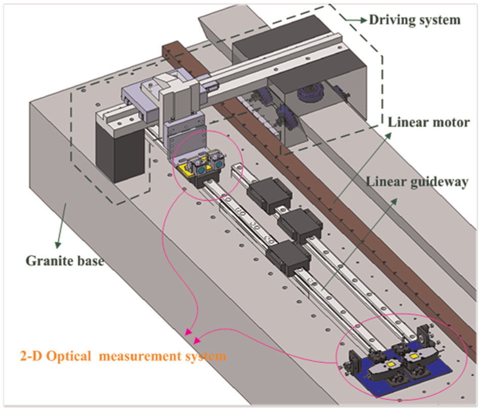
Sketch of the setup for the 2D optical measurement system.
Component specifications of the precision linear positioning stage.
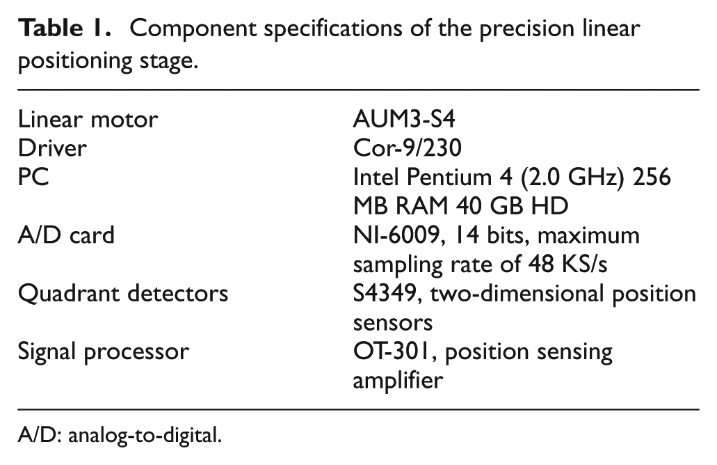
A/D: analog-to-digital.
Optical configuration design
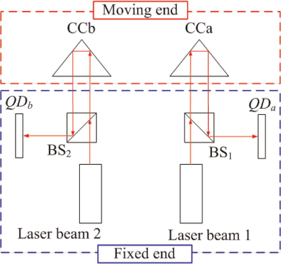
As shown in Figure 2, the 2D optical measurement system has a fixed end and a moving end. The fixed end has two laser beams, two BSs,
12
and two QDs.
13
The moving end has two CCs.
14
The measurement process begins with the two CCs being bilaterally assembled on the top surface of the carriage. The QDs are 2D position sensors that can detect translational displacement. While the carriage is in linear motion, light beams reflected by the CCs on top of the carriage are changed and detected by QDa and QDb, allowing
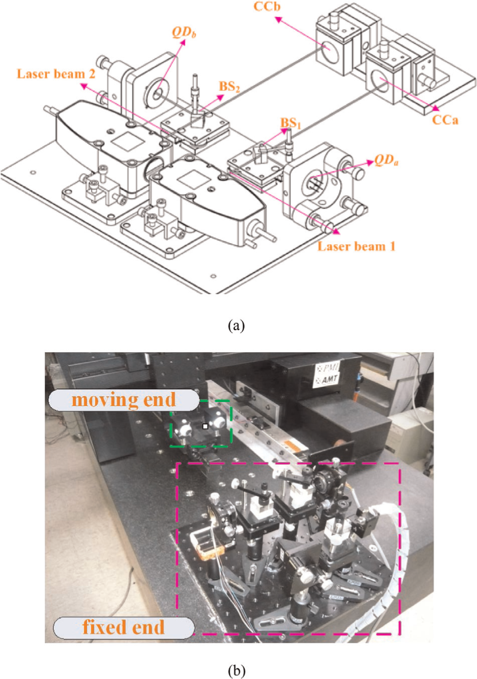
(a) Sketch of the 2D optical measurement system and (b) physical setup of the 2D optical measurement system.
Principle for the 2D optical measurement system
The position deviations of the light spot in the CCs are shown in Figure 3. After calculation and measurement, the horizontal straightness (


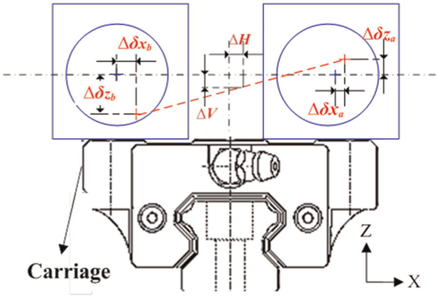
Sketch of the position deviation of the light spot in the corner cubes.
The optical paths of the measurement system are shown in Figure 4. The laser beam emitted by one of the laser units passes through BS1 and becomes an incident light beam that shoots to the corresponding CC. After being reflected by the three boundary surfaces of the CC, the light beam leaves the cube as a parallel collimated light beam, which is refracted by BS1, and then is projected onto QDa. By the same principle, the other laser beam follows a similar path into QDb. The CCs are the major reflectors in the system and can be used to increase the resolution of the measurement system k-fold. The optical characteristics of the CCs are shown in Figure 5. Therefore, the equations can be modified as


where
Sketch of optical paths in the proposed measurement system.
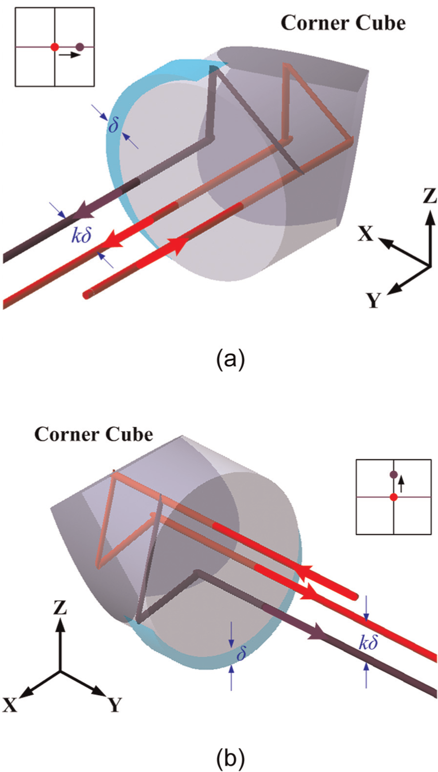
Sketch of increased resolution: (a) moving alone x-axis and (b) moving alone z-axis.
Discussion
Calibration results for the 2D optical measurement system
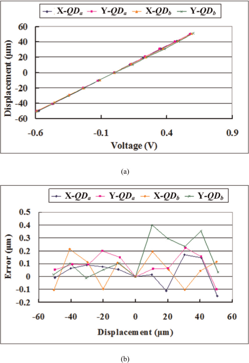
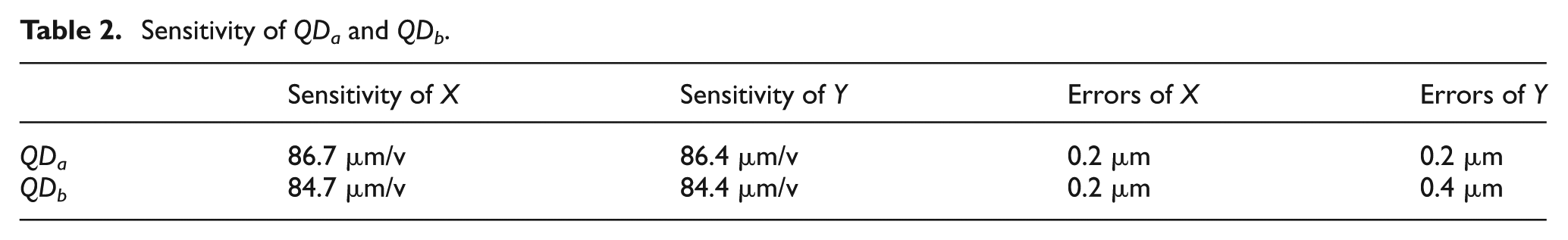
The QDs are the main sensors in the proposed system. In order to transform voltage values into displacement values, the sensitivity of the QD must be obtained. The calibration results of the system are obtained using a laser interferometer (HP 5529A), as shown in Figure 6. The investigation consists of recording the output voltage from the QDs at measurement range from −50 to 50 µm in a step of 10 µm. The calibration results of QDa and QDb are shown in Figure 7. The sensitivities of the QDs are described in Table 2. The sensitivities of QDs are about 86 and 84 µm/v in the measurement ranges of 50 µm, respectively. In the three tests, the residual errors of QDa and QDb are about 0.2 and 0.4 µm, respectively. The standard deviations (SDs) of the three tests of QDa and QDb are about 0.9 and 1 µm, respectively.
Sketch of the calibration system.
Calibration results of QDa and QDb: (a) sensitivities of QDa and QDb and (b) errors of QDa and QDb.
Sensitivity of QDa and QDb.
Verification results for the 2D optical measurement system
A linear guideway and the fixed end of the proposed measurement system were installed on the precision granite air-floating table. The moving end of the system was fixed on the carriage. The 2D optical measurement system was verified using a laser interferometer (HP 5529A), as shown in Figure 8. Figures 9 and 10 show the results of three straightness measurements. The SD of the 2D optical measurement system is about 0.4 µm in the measurement range of 100 mm. The precision linear positioning stage reduces measurement time and removes human error.
Sketch of the verification system: (a) horizontal direction and (b) vertical direction.
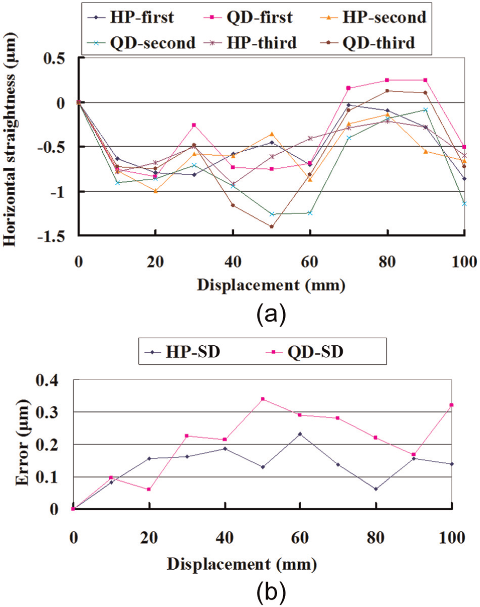
Verification results of horizontal straightness: (a) results of verification and (b) SD.
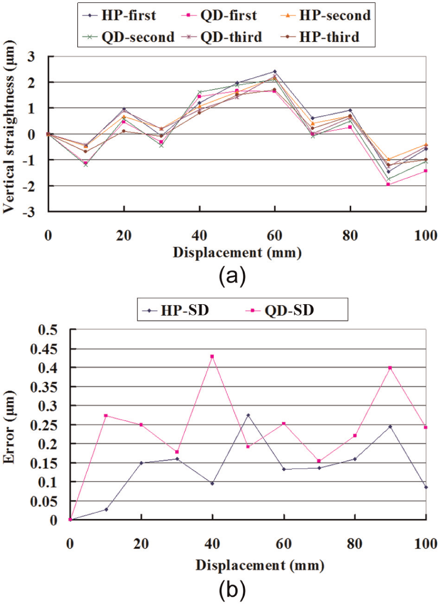
Verification results of vertical straightness: (a) results of verification and (b) SD.
Measurement results for the linear guideway
Tests were repeated, and the measurement parameters were set as follows. For the straightness measurement, the sampling frequency was 1000 Hz, the measurement distance was 1000 mm, and the measuring pitch was 6 mm. The results are shown in Figure 11. The SDs of the horizontal and vertical straightness measurement systems are 0.9 and 1.2 µm in the measurement range of 1000 mm and the measuring time is 80 s. The possible sources of error in the QDs can be due to fluctuation of collimated laser source, stray light, and possible external environment vibrations.
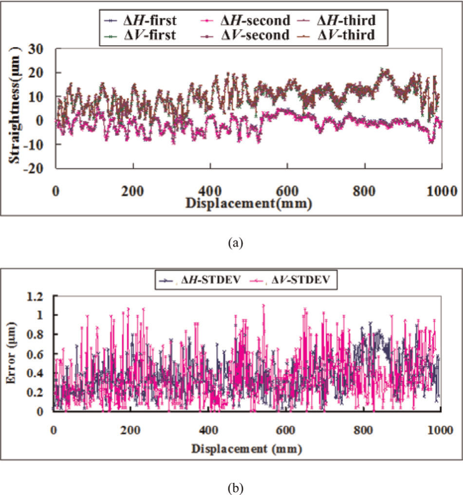
Results of horizontal and vertical straightness measurements: (a) results of three tests and (b)STDEV.
To reduce these effects, the following precautions can be taken: (1) A well-regulated power supply is used for the collimated laser and this minimizes the fluctuation of light source intensity, (2) the fixture is designed so that the stray light and room light do not interfere with the light source intensity, and (3) the sampling rate of analog-to-digital (A/D) card is increased to avoid the leakage effect.
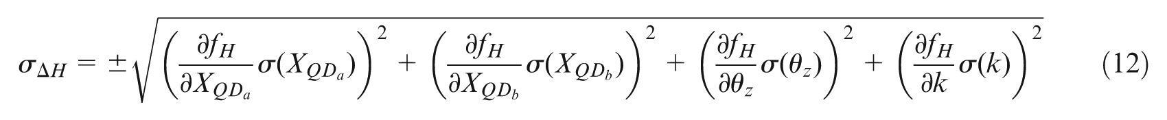
In order to estimate the uncertainty of the proposed precision linear positioning stage in the measurement ranges of 1000 nm, each measuring element is estimated using partial differentiation. Suppose that each measuring element Fi is a function of a number of individual signals, si, from the QDs and positional parameters. The composite error of Fi can be expressed as

where dFi is the accuracy of measuring element Fi. When the QDs are assembled in the 2D optical measurement system, angular errors


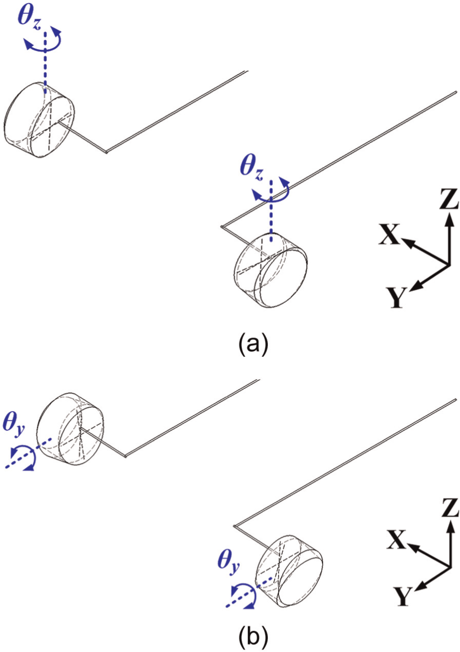
Sketch of the setup error of the QD: (a) setup error around z-axis and (b) setup error around y-axis.
The formula for the sensitivity analysis can be defined as


where


The angular errors
The
Conclusion
The prototype simple 2D optical measurement system measured the horizontal and vertical running straightness errors for the linear guideway. It was an effective method for online error measurement to improve linear guideway performance. This advantage is superior to other useful methods. In the future, a static/dynamic multifunction measuring device will be designed and more powerful for online measuring the motion errors of the linear guideway.
Footnotes
Appendix 1
Acknowledgements
This article has neither been published nor been submitted for publication elsewhere.
Declaration of conflicting interests
The authors declare that there is no conflict of interest.
Funding
This research was supported by the National Science Council, Taiwan, Republic of China (number: NSC 97-2622-E-150-001).