
Abstract
The optical performance of the off-axis three-mirror imaging system can be greatly improved using freeform surfaces. This article focuses on the polishing of the primary mirror and tertiary mirror in an off-axis three-mirror imaging system. The primary mirror and tertiary mirror are fabricated on one monolithic substrate and described by non-uniform rational B-spline–based freeform surfaces. The separated and integrated polishing strategies are presented for polishing the two mirrors on the four-axis computer numerical control polishing platform. A tool path generation approach is proposed for polishing of the non-uniform rational B-spline–based freeform surface. Three kinds of the tool paths are given for ultra-precision polishing of the primary mirror and tertiary mirror with the freeform surfaces. The concentric circle path and the approximately concentric circle path are generated for polishing two mirrors separately, while the spiral path is calculated for integrated polishing of two mirrors simultaneously. The polishing tool posture along the planned tool paths is also analyzed. The ultra-precision polishing experiments of the primary mirror and tertiary mirror on the four-axis computer numerical control polishing platform are performed to verify the proposed approach for tool path generation.
Keywords
Introduction
Freeform optical surfaces are widely used in modern optical systems because of many advantages, such as flexible optical design, excellent optical performance and simplified system structure. The application of the freeform surface in the off-axis three-mirror imaging system can obtain higher optical performance and system specifications. 1 The freeform surfaces have been defined as surfaces with no axis of rotational invariance within or beyond the part. 2 Many description methods of the freeform surfaces have been used in freeform surface modeling, such as elementary functions, general XY polynomials, Zernike polynomials and non-uniform rational B-splines (NURBSs). The demand of high-precision freeform optical surfaces with submicron form accuracy and nanometric surface finish offers new challenges for optical manufacturing, measurement and testing.
Several different manufacturing processes have been developed for fabrication of the freeform surfaces, such as the slow slide servo and fast tool servo for diamond turning,3–6 ultra-precision milling, 7 fly-cutting 8 and ultra-precision grinding.9,10 Although the above processes can fabricate high-precision freeform optical surfaces, there still exist some defects on the machined surface, such as tool marks after diamond turning or raster milling, surface texture and subsurface cracks after grinding. To obtain the freeform optical surfaces with sub-micrometer form accuracy and nanometer surface finish, ultra-precision polishing as a post process is used to remove these surface defects and correct the form deviation.11–15
In ultra-precision freeform polishing, the spinning polishing tool moves along the tool path and contacts with the freeform surface with a constant normal pressure. According to Preston’s law, 16 the material removal is proportional to the polishing pressure and the relative velocity between the polishing tool and workpiece. The material removal along the direction of the tool path can be controlled by adjusting the feed speed of the polishing tool, while the material removal perpendicular to the tool path is determined by the overlapping of the tool paths. The dwell time map can be calculated by solving a set of mathematical equations about the tool influence function (TIF) and error map obtained by measurement. The form deviation all over the freeform surface can be corrected by multi-passes of polishing and measurement.
Because of the complexity of the freeform surface and the contact condition, it is very difficult to ensure a deterministic material removal and accurate form error correction during polishing. There are several factors affecting the ultra-precision polishing process, such as the polishing path, the polishing slurry, the polishing strategy, TIF and surface measurement. Walker et al.17,18 developed the Precessions™ polishing process for aspheric surface form correcting based on the IRP200 computer numerical control (CNC) polishing machine, which has the ability to both polish precision ground surfaces and control form down to the optical diffraction limit. Cheung and colleagues19,20 studied the factors affecting surface generation in ultra-precision freeform polishing and found that surface generation is significantly affected by the influence function and the desired surface roughness can be achieved by appropriate combinations of mechanical polishing and fluid jet polishing. Fan et al. 21 predicted the material removal in freeform surface polishing by modeling the local and the global polished profiles. Pan et al. 22 established the motion model of particle trajectories on polishing contact region by analyzing the relative motion between the bonnet tool and workpiece and proposed a vertical continuous precession polishing method for aspheric lenses, by which the texture on the contact zone was approximately random and uniform.
The tool path for ultra-precision polishing directly impacts the uniform coverage of surface as well as the residual error after polishing. Furthermore, the tool path used for freeform polishing must be acceleration-smooth enough to accommodate the dynamic performance of CNC machine tool. Many kinds of polishing paths have been presented by researchers, such as scanning path,23–26 peano-like path 27 and pseudorandom path. 28 However, these paths are limited to flat or simple surface polishing and need complicated machine tool movement, which is not practical for freeform surface polishing.
In this article, the tool path generation approach for polishing of the primary mirror and tertiary mirror in an off-axis three-mirror system is proposed for constructing the iterative polishing loop. The two mirrors are fabricated on one monolithic substrate and described by NURBS-based freeform surfaces. The polishing strategies and iterative polishing process for the freeform mirrors are presented in section “Ultra-precision polishing of freeform mirrors.” The transformation from the parametric domain of the NURBS surfaces to Cartesian coordinate system is described in section “Transformation of NURBS-based freeform surfaces.” In section “Tool path generation for freeform mirror polishing,” three kinds of tool paths are calculated for the freeform mirrors according to the proposed polishing strategies. The polishing tool posture along the tool paths is also analyzed in section “Determination of polishing tool posture and the inverse kinematics.” The generated tool paths are verified by the polishing experiments in section “Tool paths and polishing experiments.” The conclusions are summarized in section “Conclusion.”
Ultra-precision polishing of freeform mirrors
Polishing strategies
An off-axis three-mirror imaging system investigated in this article is constructed by integrated optical design method and consists of two separated NURBS-based optical surfaces (as shown in Figure 1), which can improve the optical performance in theory. But the separated layout of the primary mirror and tertiary mirror on one monolithic substrate brings more difficulties for polishing.
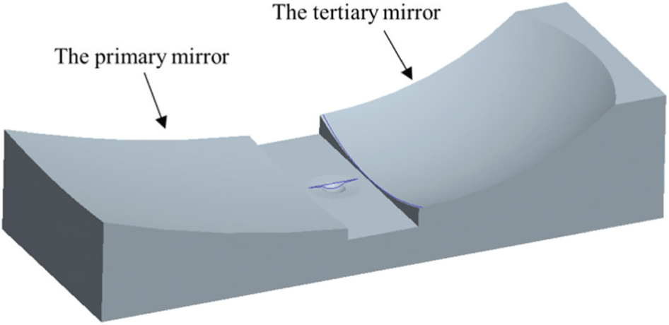
The 3D model of the freeform mirrors.
There are two strategies for polishing of the freeform mirrors. The first one is separated polishing, and the second is integrated polishing. For the separated polishing, the two optical surfaces can be polished sequentially, during which the polishing tool contacts with the workpiece surface continuously except shift between two surfaces. For the integrated polishing, the two optical surfaces are polished simultaneously, by which the same polishing conditions for the two surfaces can be maintained.
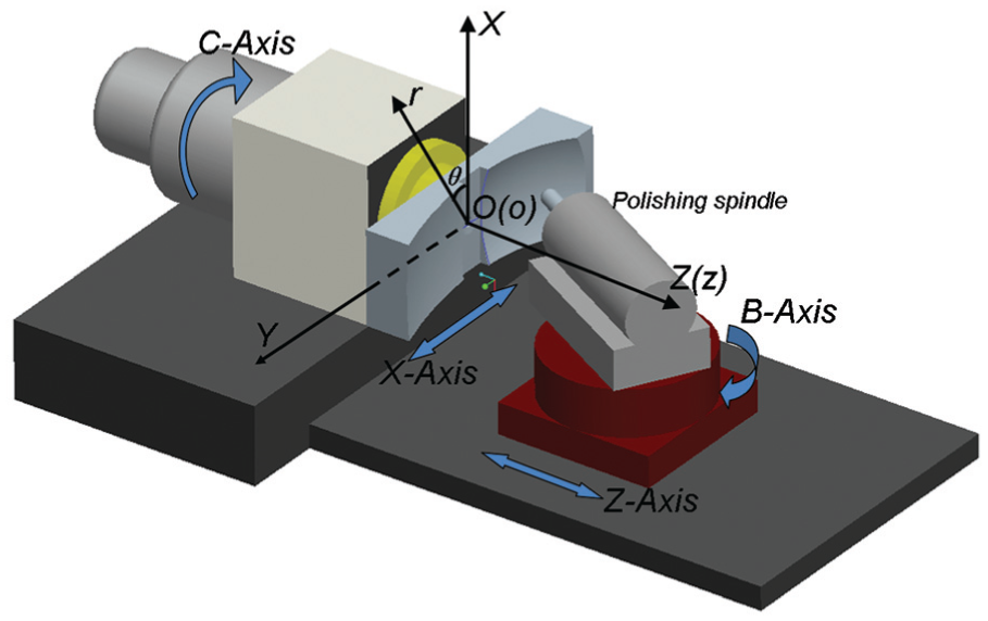
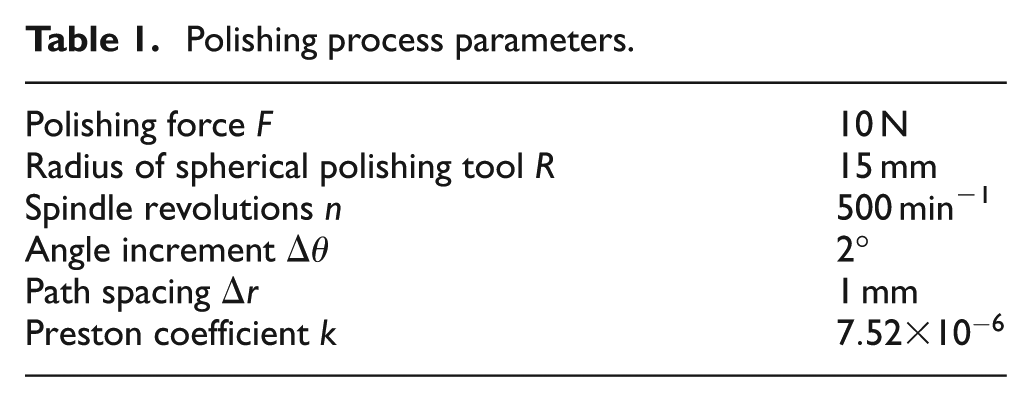
In this article, a four-axis CNC polishing platform with the flexible polishing tool is used for polishing of the freeform mirrors under the two polishing strategies. As shown in Figure 2, the four-axis CNC polishing platform is composed of two translational axes (X-axis and Z-axis) and two rotational axes (B-axis and C-axis). The workpiece is mounted on the C-axis and can move along the X-axis. The polishing spindle is mounted on the B-axis and can move with the Z-axis.
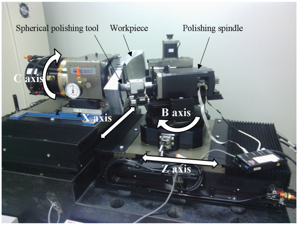
Configuration of the four-axis CNC polishing platform.
According to the configuration of the four-axis CNC polishing platform, the freeform mirror can be polished in the cylindrical coordinate system. The separated polishing strategy is accomplished by the sway motion of the C-axis and the translation of the X- and Z-axes, whereas the integrated polishing strategy is carried out by a continuous rotation of the C-axis with the translating of the X- and Z-axes. The force-controlled polishing spindle can maintain a constant polishing posture relative to the mirror surface by B-axis rotation. As the shape of freeform mirror is concave, the spherical polishing tool is used to comply with the curved surface.
Iterative polishing process
In this article, the iterative polishing loop consisting of optical design module, freeform polishing module and surface measurement module is built for polishing of the primary mirror and tertiary mirror in an off-axis three-mirror system. As shown in Figure 3, in the optical design module, the shape of the freeform surface is determined and two NURBS-based freeform surfaces are constructed. The freeform mirror is fabricated by CNC milling based on the results of optical design. In the freeform polishing module, the tool paths are generated according to the proposed polishing strategies. The concentric circle path (CCP), the spiral path (SP) and the approximately concentric circle path (ACCP) are generated, respectively, for comparison, which is the focus of this article. Then, the dwell time, defined by the feed speed of the polishing tool along the polishing path, is calculated by solving a set of mathematic equations constructed on the basis of material removal function. The polishing operation is then carried out according to the planned tool path and feed speed on the polishing platform, which is followed by an online measurement process. According to the error map obtained by measurement, if the form error
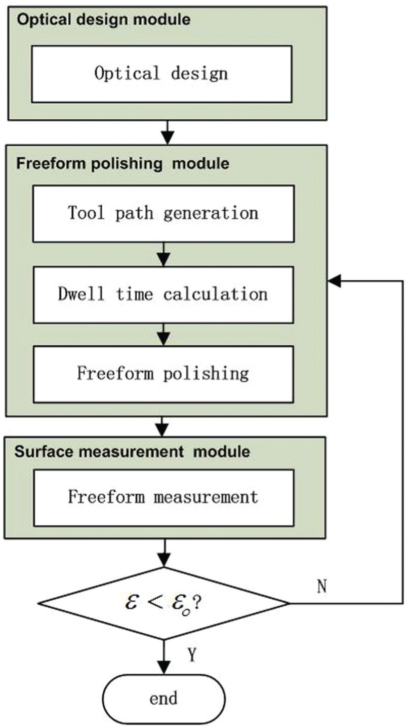
Iterative polishing loop of freeform optical surfaces.
Tool path generation is an important and fundamental part in the overall iterative polishing loop. This article focuses on tool path generation for polishing of the primary mirror and tertiary mirror. The issues on dwell time calculation and freeform polishing process in the iterative polishing loop will be discussed in the future work.
Transformation of NURBS-based freeform surfaces
In freeform optical surface machining, NURBS provides a much more flexible and elegant method with advantages such as easy data exchange and precision persistence to describe the freeform surface than other description methods.
29
However, the parametric expression of NURBS surface cannot be used for tool path generation directly. In this study, the polishing operation of the freeform mirror is carried out in the cylindrical coordinate system, so the translation from parametric domain (
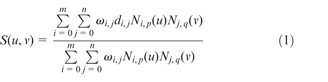
The general expression of NURBS surface is 30
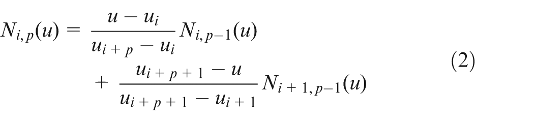
where

The knot vector with the length of

According to Krishnamurthy et al.,
31
when the parametric domain of the NURBS surface is meshed into regular distributed points, the points in Cartesian coordinate system corresponding to the regular distributed points can be calculated by the direct evaluation method. First, the parametric domains (0, 1) in u- and v-directions are divided into
For the evaluation point (
Find the span of
Compute the non-zero basis functions
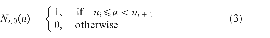
The recursive expression in v-direction has the same format as equations (2) and (3).
Multiply the non-zero basis functions with their corresponding control points and sum the results; the point
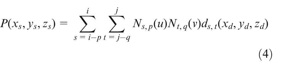
For the NURBS surface of the primary mirror, the B-spline basis functions in the two directions have the same degree of 5 and all the weight factors are 1 (

and

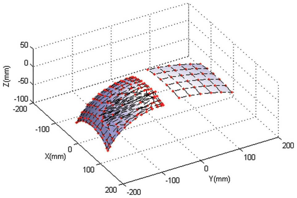
The evaluation points in Cartesian coordinate system are calculated using this direct evaluation method. Similarly, the NURBS surface of the tertiary mirror can be translated into the Cartesian coordinate system. Figure 4 shows the control points of the original NURBS-based freeform optical surfaces. Figure 5 shows the regular evaluated points on the freeform surfaces in Cartesian coordinate system.
Control points of the NURBS-based freeform optical surfaces on the primary mirror and tertiary mirror.
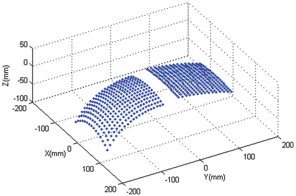
Regular evaluated points on the freeform optical surfaces on the primary mirror and tertiary mirror.
Tool path generation for freeform mirror polishing
CCP and SP
As shown in Figure 6, the part coordinate system (O-XYZ) is constructed by setting the origin O on the center of part bottom, the Y-axis of the part coordinate system is parallel to the long edge of part bottom while the X-axis of the part coordinate system is parallel to the short edge. The tool path is generated in the machining coordinate system (
Part coordinate system (O-XYZ) and machining coordinate system (
The driven path for the CCP is a set of concentric circles, which can be expressed as

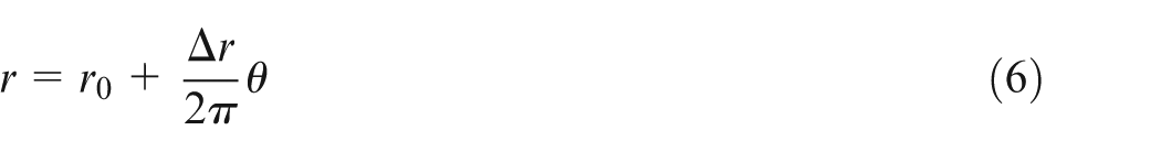
The driven path for SP is a spiral expressed by
where

where
Because the freeform surface has been decomposed into discrete points (

where
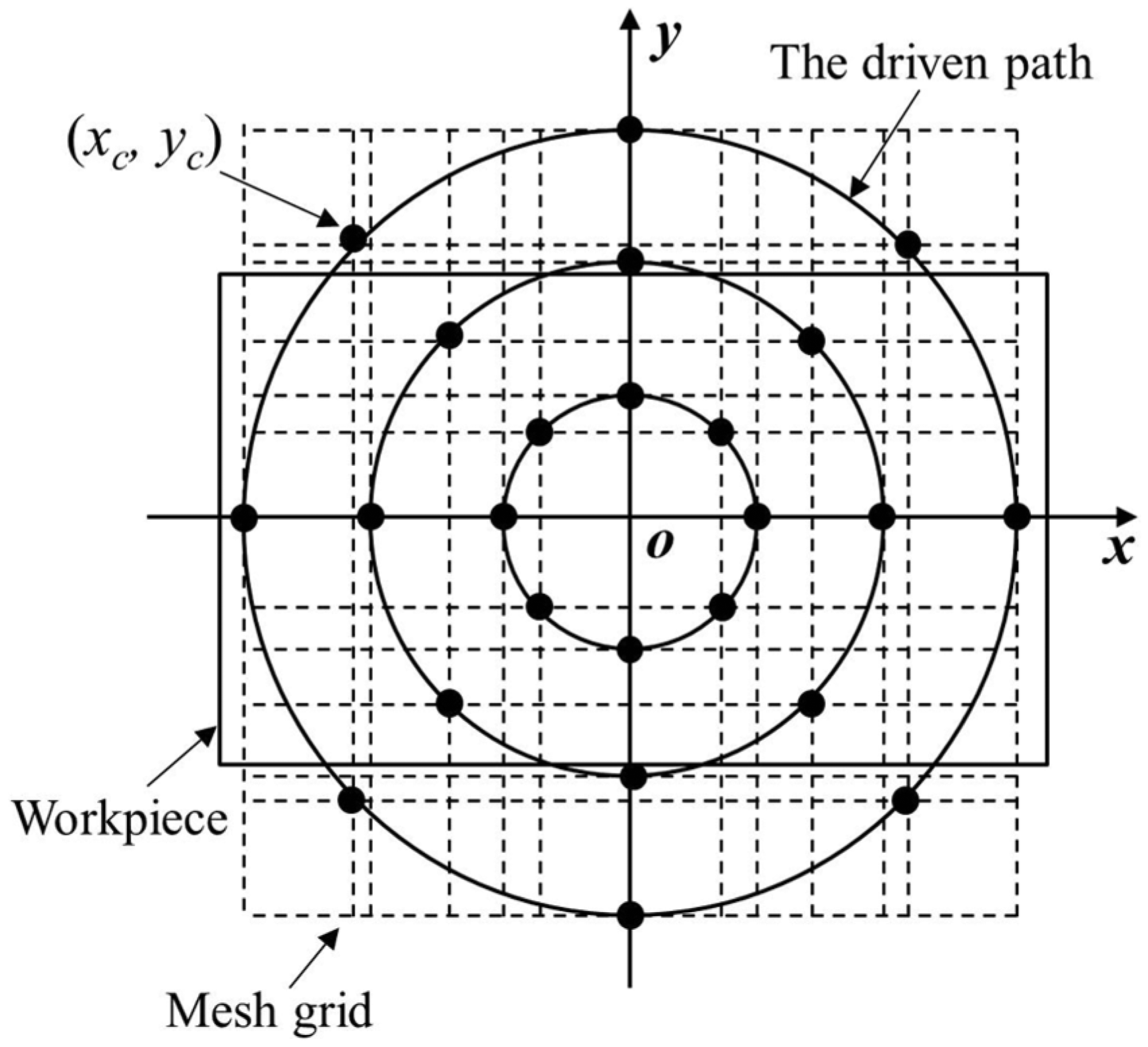
Mesh grid on driven plane of CCP from the top viewpoint.
ACCP
For CCP and SP, the tool contact path spacing on the freeform surface is uneven because the same increment
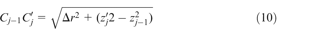
The equal spaced tool contact path is generated by a searching algorithm. The initial circle tool contact path passing through two corners of the design surface is generated as shown in Figure 8(a). The polar radius for this path in the cylindrical coordinate system is given by

where (
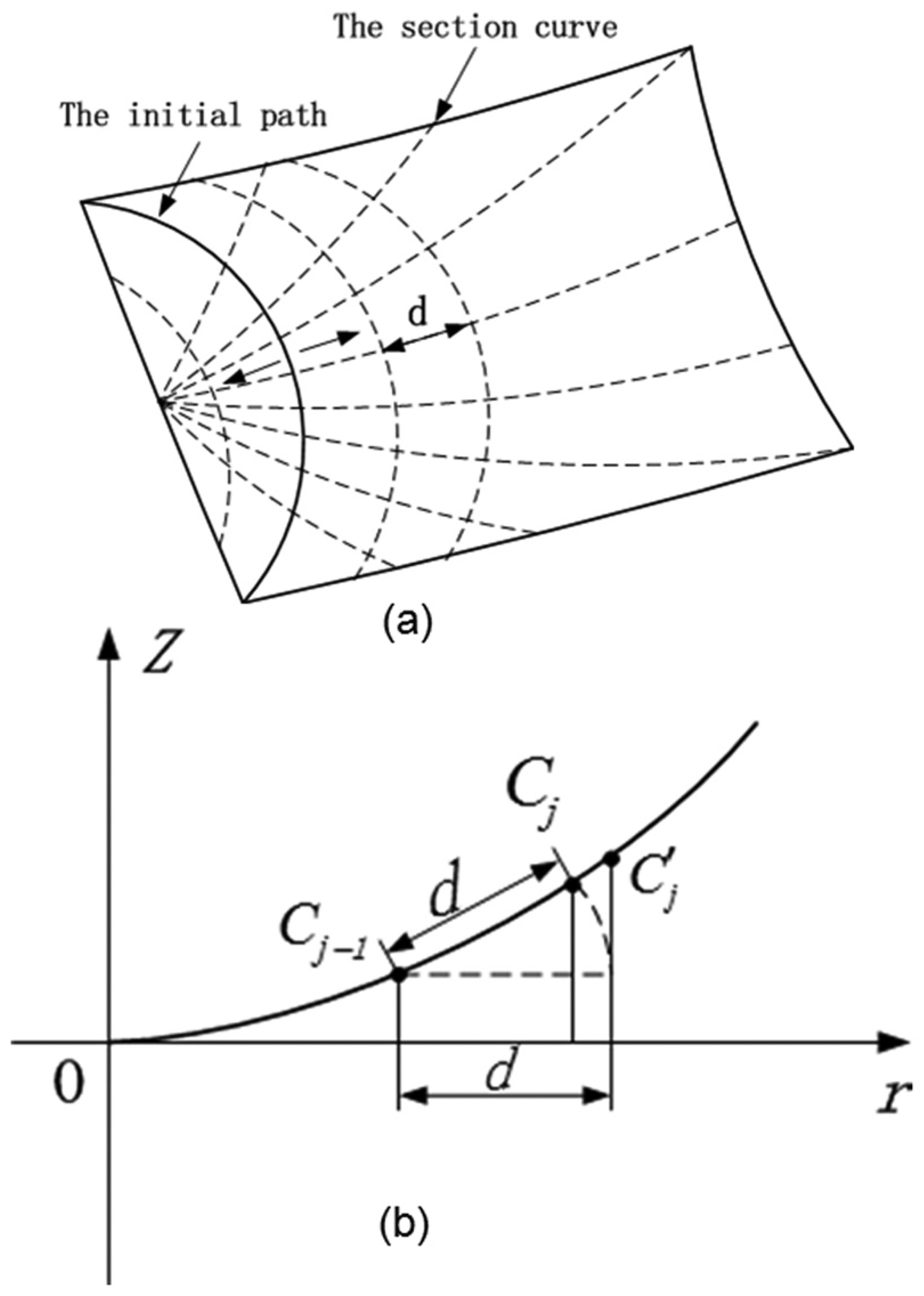
Calculation of tool contact paths with equal spacing for ACCP on the primary mirror (a) The tool contact path and (b) The section curve.
When the section curve at polar angle
Step 1. Let j = 1.
Step 2. Let
Step 3. Calculate the distance of
Step 4. If

Step 5. If
In this searching algorithm, if
Determination of polishing tool posture and the inverse kinematics
The tool used in freeform surface polishing is usually flexible in the material to comply with the curved surface. The spherical tool made of solid elastic material or bonnet inflated by air pressure is the most common polishing tool for freeform surface polishing.33,34 As shown in Figure 9, the tool location point
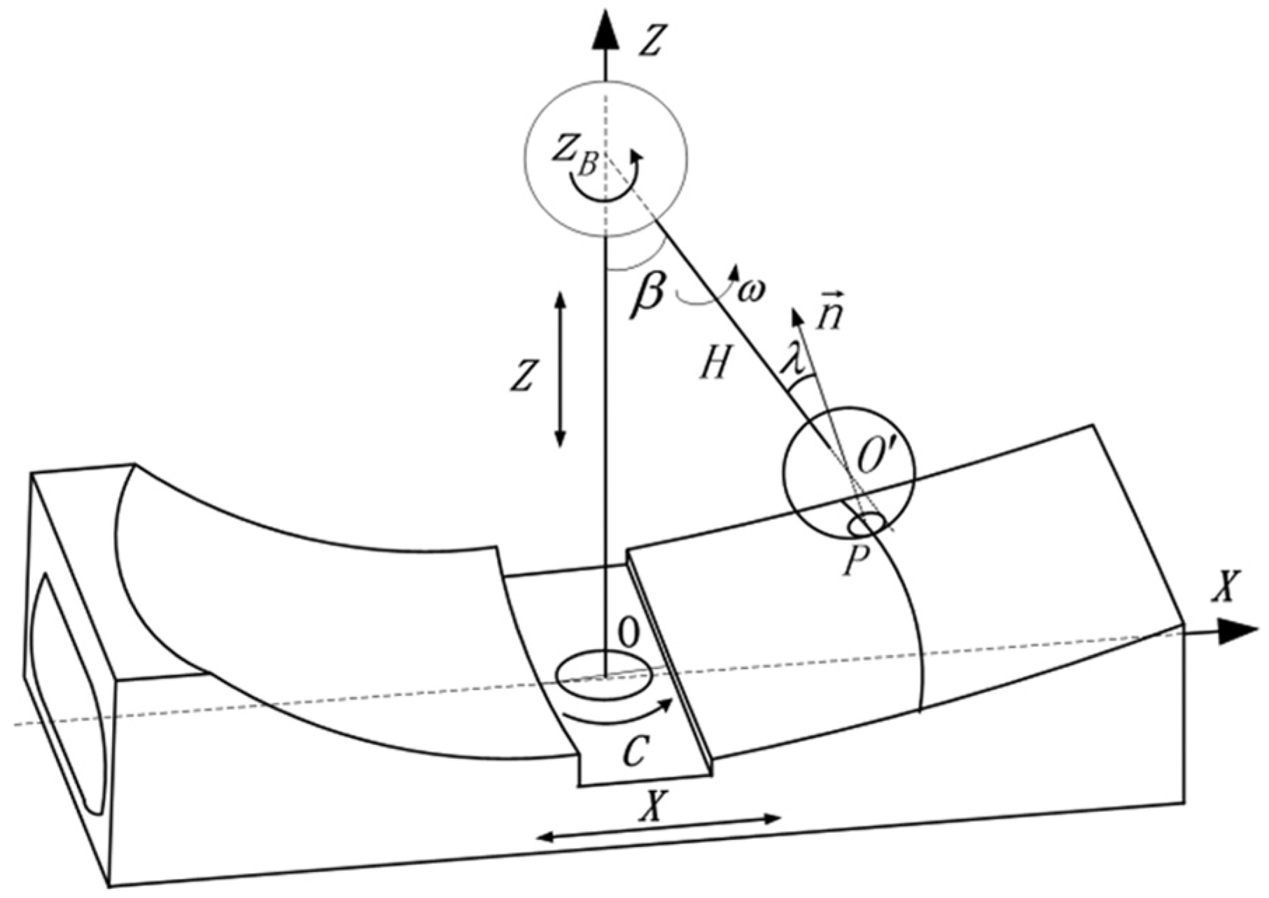
Geometrical illustration for polishing of the primary mirror and tertiary mirror.
In Figure 9, the polishing posture is described by the polishing inclination angle
If the unit normal vector at point P is {
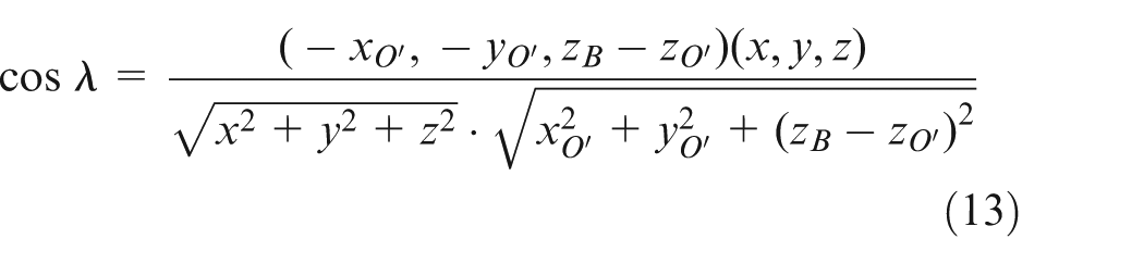
where
From equations (12) and (13), it is derived as

that is

From equations (12) and (15), a quadratic equation about
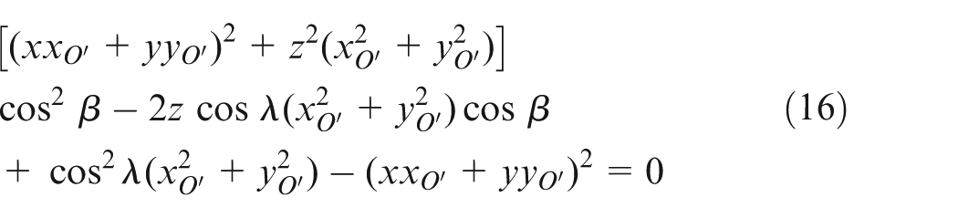
The value of

where

Schematic diagram of inverse kinematics for polishing of the primary mirror and tertiary mirror.
From equations (17) and (18), it is derived as
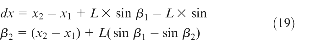
The displacement increment of Z-axis
Tool paths and polishing experiments
Generated tool paths
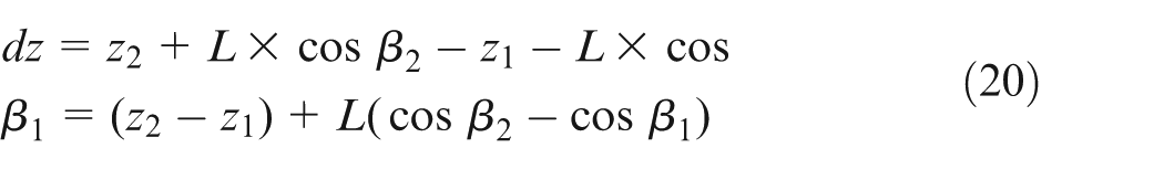
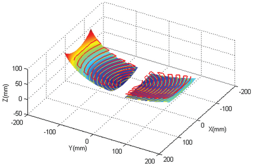
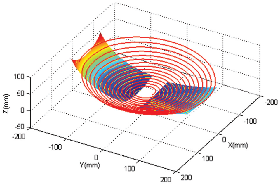
According to the approach to generate the tool paths for freeform mirror polishing proposed in this article, the actual CCP, ACCP and SP are calculated using the MATLAB software package. Figures 11–13 show the generated tool contact paths and tool paths for polishing of the two freeform mirrors, where the spacing of the tool paths has been assigned a large value for illustration purpose. Figure 11 illustrates the CCP for the separated polishing strategy. The driven path spacing
Concentric circle path (CCP) for the primary mirror and tertiary mirror.
Spiral path (SP) for the primary mirror and tertiary mirror.
Approximately concentric circle path (ACCP) for the primary mirror and tertiary mirror.
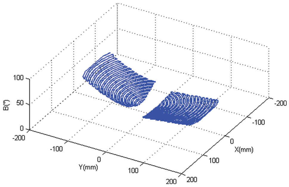
Angles of B-axis along ACCP.
Polishing experiments and results
The experiments for polishing of the primary mirror and tertiary mirror have been carried out to verify the generated CCP, SP and ACCP on the four-axis CNC polishing platform, respectively. The spherical polishing tool (as show in Figure 15) used in the experiment is made of polyurethane and covered with the polishing cloth. The workpiece material is 6061 aluminum alloy and alumina with the sizes of 5, 10 and 15 μm in water-based solvent is used as the polishing slurry. As the polishing process is very time-consuming, the generated CCP, SP and ACCP are verified in the fast task mode. The practical polishing experiment is conducted on the primary mirror using CCP with path spacing
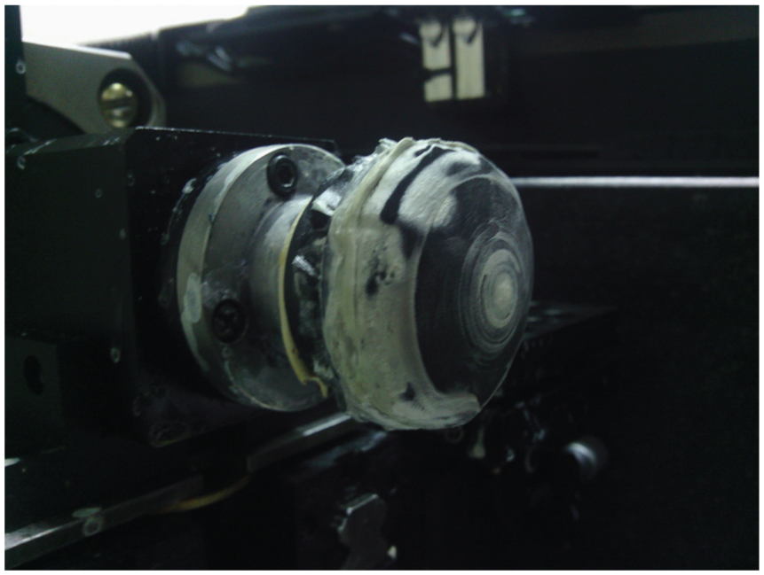
Spherical polishing tool.
Polishing process parameters.
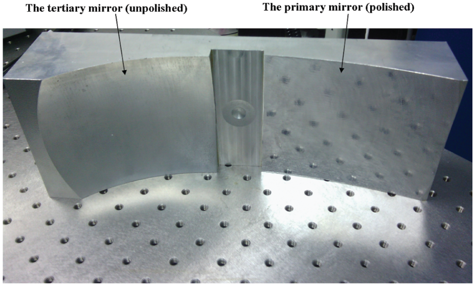
A comparison of the polished primary mirror and the unpolished tertiary mirror.
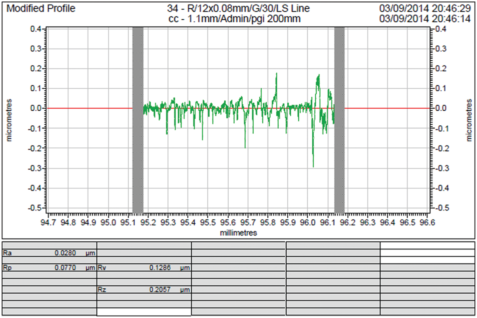
Surface roughness of the primary mirror.
Conclusion
Tool path generation is a crucial step in the iterative freeform surface polishing process. This article investigates the tool path generation approach for polishing of the primary mirror and tertiary mirror in the freeform off-axis three-mirror imaging system. The separated and integrated polishing strategies and the iterative polishing process are presented for polishing of the primary mirror and tertiary mirror, which are fabricated on one monolithic substrate and described by NURBS-based freeform surfaces. The NURBS surface in the parametric domain is transformed to Cartesian coordinate system and cylindrical coordinate system for convenience of tool path generation.
In particular, this article focuses on tool path generation for polishing of the primary mirror and tertiary mirror in an off-axis three-mirror imaging system. The CCP driven by a set of concentric circles on driven plane is calculated for polishing the primary mirror and tertiary mirror separately, while the SP driven by a spiral is calculated for polishing the primary mirror and tertiary mirror simultaneously. In consideration of the arbitrary shape of freeform surface and the ill-conditioned equations in dwell time calculation, the ACCP is calculated based on a searching algorithm, by which the equal spaced tool contact path on the freeform surface can be generated. In order to keep a certain polishing posture, the angular position of the B-axis along the tool path is determined by geometrical analysis.
The polishing experiments for the primary mirror and tertiary mirror are performed using the generated CCP, SP and ACCP on the four-axis CNC polishing platform respectively, which confirms the validity of the tool path generation approach for freeform surface polishing proposed in this article. After 19 passes of iterative polishing using CCP, the surface roughness of the primary mirror has been reduced to Ra 28 nm.
Footnotes
Declaration of conflicting interests
The author(s) declared no potential conflicts of interest with respect to the research, authorship, and/or publication of this article.
Funding
The author(s) disclosed receipt of the following financial support for the research, authorship, and/or publication of this article: The authors are grateful to the financial support from the National Key Basic Research and Development Program (973 program) of China (Grant No. 2011CB706702).