
Abstract
In this study, a rheology vacuum low-pressure die caster is developed by installing a vacuum system in the die and an electromagnetic stirrer in the rasing pipe of a low-pressure die casting system. The cavity dimensions are 130 mm in the filling direction and 110 mm in the vertical direction, with a thickness of 1 mm. The fluidity of the material inside the die cavity is improved by maintaining the vacuum state inside the die. The electromagnetic stirrer is attached to the outside of the rasing pipe, which connects the furnace to the lower die. The application of the electromagnetic stirrer enables the achievement of microstructure with fine and globular primary α-Al particles by disrupting the dendrite structure. A mild filling simulation is conducted using a commercial casting analysis program prior to an experiment with the rheology vacuum low-pressure die caster. The rheological behaviour of the material inside the die is observed. A rheological thin plate is fabricated by applying a melt temperature of 615 °C, a vacuum of 60 Torr, and a gas pressure of 15 bar. There is little eutectic structure, with primary aluminium grains of 30 µm or below that are mostly distributed due to the effects of stirring. The tensile strength and elongation are 120 MPa and 15%, respectively. The hardness is 61–66 HV.
Introduction
Low-pressure die casting (LPDC) is a process in which a die cavity is filled by pushing the melt against gravity through a pipe by applying a relatively small amount of pressure of 0.2–0.35 bar using a gas. LPDC is mainly used for the production of rotationally symmetric parts such as automobile wheels.
Miller and Maijer 1 investigated the state of wear according to the flow when an aluminium melt passes through a sprue during an LPDC process. Merlin et al. 2 investigated the impact energy according to the microstructure and defect conditions by constructing a wheel with A356 alloy and analysed the filling and solidification for comparison with the test results. Zhang et al. 3 conducted a solidification analysis by developing a three-dimensional (3D) heat transfer model to compare with the test results.
In the case of gravity casting, the product weight is approximately half of the injected weight. LPDC has an advantage in that at least 90% of the return scrap can be obtained. 4 However, the disadvantage is that the melt is not smoothly fed into the die, and that the defect rate and quality of the casting are not good. Gas defects inside the products and the surface density are being improved in the case of the pre-existing die casting processes by casting under vacuum in order to reduce the casting defects due to gas content. However, there are not many cases in which a vacuum has been applied to LPDC. Jiang et al. 5 constructed thin plate parts with complex shapes by applying a vacuum to the LPDC method. The resulting microstructure was finer with better mechanical properties and fewer defects compared to the case without vacuum application. Kreziak et al. 6 decreased the time needed for the developing stage by analysing filling and solidification in order to produce thin-walled products with a thickness of 2.5 mm. It is somewhat difficult to construct thin-walled products with LPDC methods, which use low forming pressure.
The goal of this research is to cast thin-walled products with a thickness of 1 mm using an LPDC method. The inside of the die was maintained in a vacuum state using a vacuum device in an established LPDC method. In particular, the focus of this study is to use a rheological material so that a semi-solid process could be applied to the LPDC. The laminar flow inside the die is induced with the effect of viscosity using an aluminium melt at temperatures below the liquidus line. The grains of the aluminium material are controlled by connecting an electromagnetic stirrer to the rasing pipe through which the melt moves.
A semi-solid process is a technique for forming with a press machine by making the material into slurry in a rheological state, which is the boundary between the solid and liquid phases. The defects due to gas or pores inside the product can be reduced since the melt is fed into the die in a laminar flow state, which has higher viscosity compared to the liquid phase. This can be used to manufacture products with low thicknesses. 7,8 The methods for producing semi-solid billets began with research by professor Flemings. 9 Relevant methods include mechanical stirring, 10 slope plate processes, 11 and electromagnetic stirring (EMS), 7,12,13 in which the melt is stirred with electromagnetic force, as well as gas-induced semi-solid (GISS) 14 and ultrasonic vibration methods. 15 Among these techniques, the EMS method produces rheological material (in a semi-solid state) with globular and fine primary particles through the application of shear force to the melt area, which disrupts the dendritic structure that occurs during aluminium solidification. Research on forming products through a forging press or die caster by producing billets through EMS has been conducted, 16,17 but there has not yet been a case in which EMS has been applied to the LPDC method.
Therefore, in this study, a vacuum device was added to an established LPDC method, and a rheology vacuum low-pressure die caster (rheo-vacuum LPDC) was developed for the production of thin plates of rheological material by installing an EMS in the rasing pipe. Together with the test results from the forming process of the rheo-vacuum LPDC, an analysis program for casting (MAGMA software) was used to analyse the filling behaviour of the melt to compare with the test results. The microstructures and mechanical properties of the produced thin plates were also analysed.
Design and fabrication of rheo-vacuum LPDC
Die
The aim of this study is to fabricate a thin plate with dimensions of 130 mm × 110 mm × 1 mm. This thin plate can be applied to products such as electrical and automobile parts, bipolar plates in fuel cells, and plate heat exchangers. Before the die was machined, the shape of the die cavity was designed by filling simulation in MAGMA software, which is a commercial casting analysis program. The thin plate was first drawn using UG modelling software. The part file was converted into a stereolithography (STL) file, and filling analysis was conducted by inputting the STL file into MAGMA. Because of the 1 mm thickness of the cavity shape, which is a major factor in filling analysis, the creation of the mesh greatly affects the precision of the analysis results and the time required. Accordingly, the mesh was mainly divided into the upper and lower dies, and the cavity area was divided with a somewhat smaller mesh so that there would be at least three meshes created in the y-axis, which is the direction of the thickness. The total number of meshes including both the upper and lower dies was 4,070,000, and the number of metal cells inside the die cavity that applied to the shape of the thin plate sample was set to be 257,072. Table 1 (Value 1) shows the conditions that were used in the filling simulation.
Properties used in LPDC simulation.
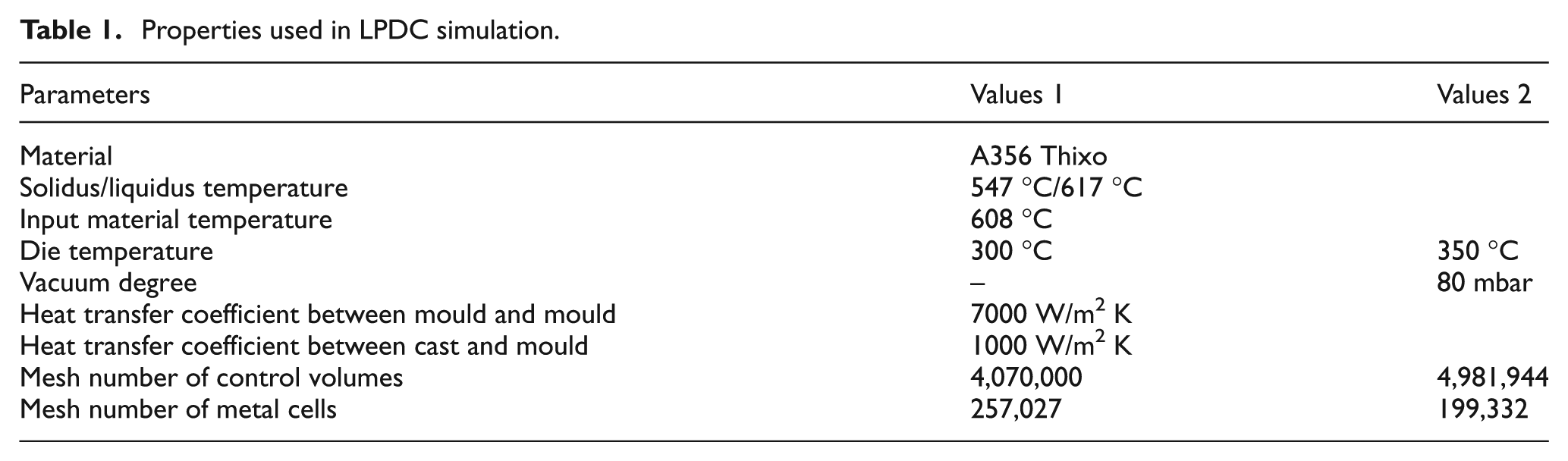
Figure 1 shows the filling behaviour by A356 alloy for the thin plate die cavity. These simulation results indicate the filling behaviour based on the amount of material filled into the die cavity. As shown in 85% of the analytical results of the filled die cavity, the filling was done along the gate’s shape as a result of the viscosity. The left and right sides of the cavity are not filled because of the narrow gate used to fill the material into the cavity. After over 85% of the die cavity was filled, the left and right sides began to be filled. This may cause a short shot at the left and right sides of the cavity, so the gate was expanded into a fan type. The design was adjusted so that the material could fill up the entire cavity while passing through the gate overflow, and a vacuum bent was designed. Figure 2 shows the shape of the die cavity designed through the filling simulation.
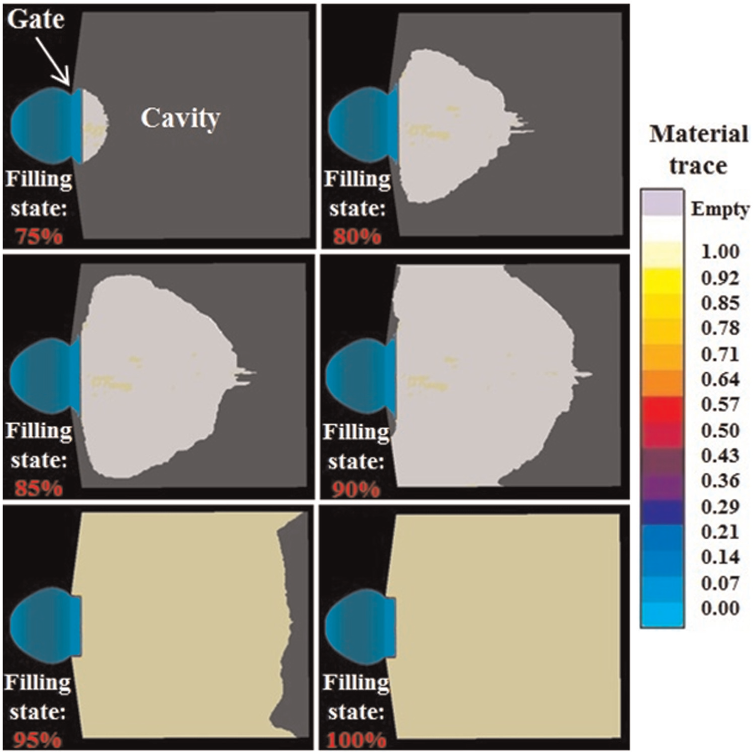
Filling behaviour (material trace) of thin plate using A356 Thixo alloy in MAGMA software.
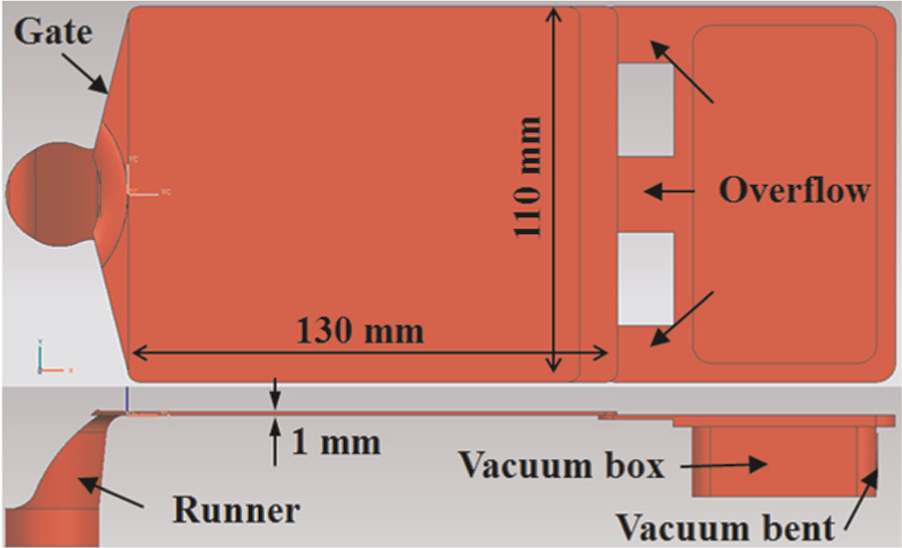
Geometry of die cavity.
Rheo-vacuum LPDC
Figure 3 shows the schematic diagram of the rheo-vacuum LPDC with the EMS. This process is similar to the established LPDC process, in which the aluminium melt passes through the rasing pipe and enters the die cavity due to pressure from argon gas that is fed in through an inlet located at the top of the furnace. However, for the apparatus used in this experiment, an EMS was attached to the outside of the rasing pipe that connects the furnace to the lower die in order to produce the rheological thin plates. With the application of the EMS, fine and globular primary α-Al particles are to be obtained by controlling the dendrite structure that occurs during the solidification of aluminium material when the aluminium melt passes through the rasing pipe. Figure 4 shows the schematic diagram of the EMS. The EMS is a horizontal stirrer that has been constructed in three phase with three poles. The electromagnetic field is formed according to the shape of the coil and core using three-phase electricity, and the melt is stirred in the circumferential direction horizontally through the electromagnetic field generated by a coil installed perpendicular to the core. The EMS system is composed of an electromagnetic stirrer, an electric current controller that controls the output, and a cooling device for the coils inside the stirrer. During the EMS, the temperature increases due to the radiated heat from the melt, and this may cause the coil to burn. To prevent this, a cooling device was designed for inside the coil. The stirring force generated acts as shear force on the aluminium melt and disrupts the dendrite structure that is created during solidification, through which the solid grain size is controlled. 18
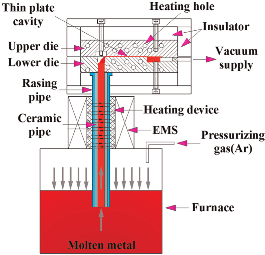
Illustration of rheo-vacuum LPDC process.
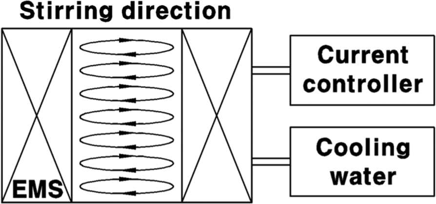
Illustration of EMS apparatus.
In order to control the temperature of the aluminium melt that passes through the rasing pipe, a heating device that wraps around the whole exterior of the rasing pipe was designed, and a cartridge heater was attached to the connecting part of the furnace and the rasing pipe in order to improve the fluidity of the material. The rasing pipe was manufactured with SUS 316, a non-magnetic material, to prevent it from being affected by the stirring effect of the EMS.
When the casting process is continued for a prolonged duration, solidification of the melt occurs due to the sticking characteristics of the aluminium inside the rasing pipe. To prevent such problems from occurring, the rasing pipe was constructed as an integrated type with a silicon pipe inserted inside.
Because of the low thickness of 1 mm, the applied pressure from the argon gas is insufficient to fill the whole die cavity, which increases the possibility of inadequate casting. Therefore, the fluidity of the material inside the die cavity has been improved by maintaining the vacuum state inside the die while applying pressure by connecting the vacuum device to the die (vacuum bent in Figure 2).
Figure 5 shows the rheo-vacuum LPDC used in the experiment. This LPDC was constructed based on the process design drawing in Figure 3. The rasing pipe with the silicon pipe inserted is connected to the furnace, and the EMS is combined with the rasing pipe. The heating device is inserted between the rasing pipe and the EMS. The furnace combined with the EMS is inserted between the frame structure that has the die for the thin plate installed, and the top of the rasing pipe is combined with the melt feed inlet of the lower die. The top of the rasing pipe can be connected to the melt feed inlet of the lower die more easily since the transfer plate that supports the die is designed to be able to ascend and descend through a hydraulic cylinder. By connecting the rasing pipe all the way to the gate area of the melt feed inlet in the lower die, argon gas leakage was prevented during the filling of the melt inside the die cavity. The thin plate casting die is divided into an upper and lower die, which were heated using cartridge heaters with independent temperature controls.
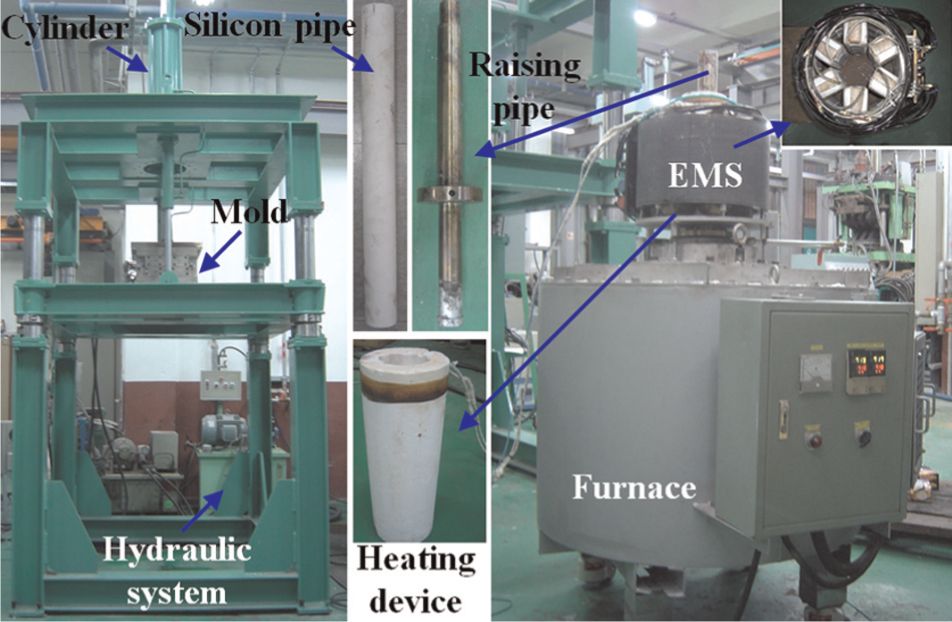
Apparatus of rheo-vacuum LPDC.
Experiment
Fabrication of slurry by EMS
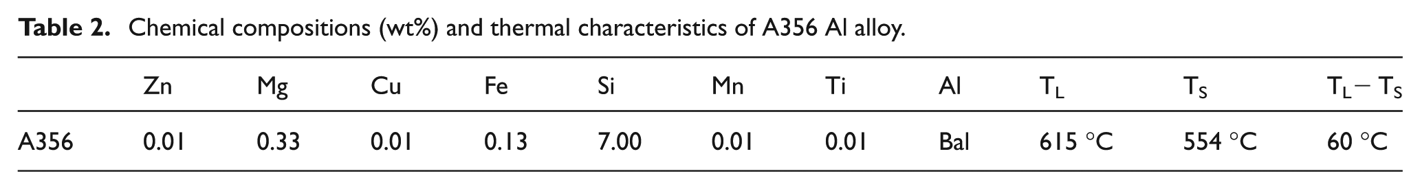
The material used for casting in the experiment was A356 aluminium alloy. Table 2 shows the chemical composition of A356 alloy and the temperatures of the solidus and liquidus lines determined through differential scanning calorimetry (DSC) analysis. Before conducting the rheo-vacuum LPDC experiment, the optimal conditions to be applied in the test were determined by conducting an experiment for the production of rheological slurry through EMS and analysing the microstructure according to the stirring current.
Chemical compositions (wt%) and thermal characteristics of A356 Al alloy.
This experiment is different from the rheological forging process wherein the slurry is produced by placing the melt inside a non-magnetic cup and applying the EMS, after which the melt fed into the forging die. In LPDC, the EMS must be applied when the melt moves through the rasing pipe due to gas pressure. Therefore, the stirring time is limited since the time that the melt spends in the rasing pipe is very short, so the EMS time was determined to be at most 4 s, since the melt may solidify if the material becomes stagnant inside the rasing pipe. To compensate for the short EMS time, a test was conducted to have an increased EMS effect by increasing the stirring force. The applied EMS stirring currents were 80 and 100 A.
In order to conduct the experiment with identical temperature conditions of the melt moving through the rasing pipe during the EMS test, the EMS cup was constructed with an identical material, inner diameter (35 mm), and thickness (12.5 mm) to those of the rasing pipe, as shown in Figure 6. The experiment was set up to have an identical maximum temperature to that of the rasing pipe by heating the cup using a heating furnace. In order to measure the temperature of the rasing pipe, holes for the thermocouple were machined on the outside of the rasing pipe.
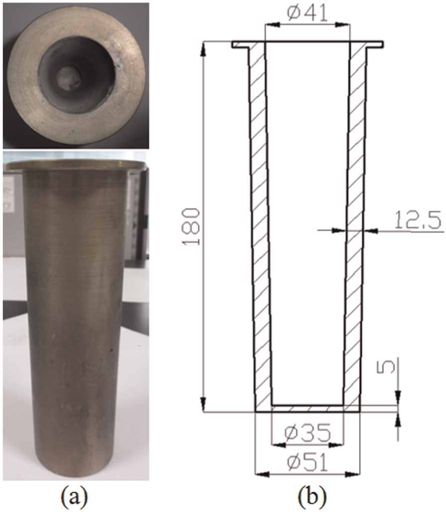
Cup for EMS experiment: (a) photograph and (b) section view.
The temperature of the melt for stirring was made to be near the liquid-state temperature (615 °C) when the melt was poured into the cup. This is because there was barely any solidification of the material inside the rasing pipe at temperatures of 610 °C or below during the pre-LPDC test, with a 15% solid fraction. The viscosity increases as well when the solid fraction of the aluminium material increases, and this causes a solidified shell to form on the walls inside the rasing pipe. This solidified shell interferes with the flow of the melt and causes the solidified shell to grow further, which then leads to solidification of the melt inside the rasing pipe. Subsequently, the EMS test was conducted by not exceeding 610 °C, which resulted in a maximum solid fraction of 15%. The semi-solid slurry with 15% solid fraction was cooled in water to observe the microstructure.
Fabrication of thin plates by rheo-vacuum LPDC
Because solidification of the melt takes place inside the rasing pipe when the temperature of the melt is low in the rheo-vacuum LPDC, the melt temperature can be set up so that the solid fraction would be 15% or below in the rasing pipe area where the EMS is applied. As the material moves through the rasing pipe at the same time that the low-temperature argon gas is pressuring the melt, the temperature of the material drops by approximately 5 °C–7 °C. Accordingly, the temperature of the A356 aluminium melt was set to be 2 °C higher than the liquidus line temperature of 615 °C.
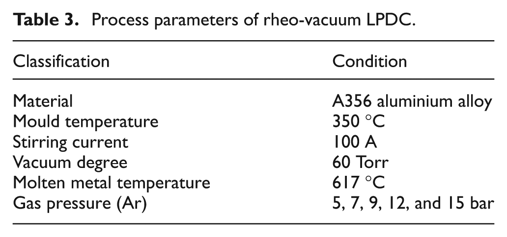
Table 3 shows the parameters that were used in the rheo-vacuum LPDC experiment. The disadvantages of having a high die temperature include having difficulty extracting the cast sample due to sticking and the surface roughness of the die becoming poor. However, because the thickness of the cavity is only 1 mm, solidification may occur as soon as the melt enters the die if the die temperature is low. Therefore, the die temperature was maintained at 350 °C. A vacuum pump was connected to the vacuum pipe at the lower die, and a 60-Torr vacuum pressure was applied. The stirring current for the EMS was set at values obtained from the EMS experiment, and the thin plate casting experiment was conducted while applying argon gas pressures of 5, 7, 9, 12, and 15 bar. The casting test was conducted five times for each set of gas pressure conditions. The formed thin plate was cooled in air.
Process parameters of rheo-vacuum LPDC.
During the rheo-vacuum LPDC experiment, the power was supplied to the EMS, and it was turned on before the argon gas was introduced. The vacuum pump was turned on at the same that the valve was opened for the argon gas inflow. The reason for this is that solidification occurred due to the melt moving all the way to the rasing pipe because of the vacuum pressure of the vacuum pump prior to the application of argon gas pressure.
Meld filling simulation of rheo-vacuum LPDC process
Meld filling simulation was conducted using MAGMA software prior to conducting the rheo-vacuum LPDC. The filling behaviour of the melt inside the die cavity was analysed and compared to the test results using the Thixo module of the A356 material used in the experiment.
The shape of the 3D modelling used in the analysis is identical to the die cavity modelling. The cavity size is 130 mm in the filling direction and 110 mm in the vertical direction, with a thickness of 1 mm. The thickness of the gate is 0.8 mm. The mesh size of the control volume was 4,981,944, and the number of metal cells was set to 199,332. Table 1 (Value 2) shows the conditions that were used in the filling simulation.
There was a slight difference between the liquidus and solidus line temperatures of the A356 alloy used in the experiment and those of the A356 Thixo applied in the MAGMA analysis program. Because the solid fraction of the material that passes through the rasing pipe was set to be 10%–15%, a temperature of 616 °C, at which the solid fraction is 10%, was applied for the simulation conditions as well. For the die temperature and vacuum pressure, 350 °C and 80 mbar (60 Torr) were applied, respectively, as in the experiment.
Figure 7 shows the temperature distribution and velocity distribution based on the amount of aluminium material with a 10% solid fraction filling the die cavity. It can be observed that the aluminium material with a solid fraction of 10% fills in a D-shape following the gate due to the effect of the viscosity. Because the thickness of the gate is thinner than the cavity by 0.2 mm, the filling velocity of the material increases at the centre of the gate, which ultimately causes the centre of the gate and the connected cavity to be filled only after the end of the cavity has been filled. Furthermore, in the velocity distribution, the filling velocity at the centre is high due to the effect of the vacuum pressure applied at the centre overflow. In addition, it can also be observed that the velocity of the material flow following the cavity wall increases gradually. Because the die temperature was set at a high value of 350 °C, the filling temperature inside the cavity was 614 °C–615 °C. As shown in the analysis results of 100% filling, the cavity side had a temperature of 614 °C and that of the cavity centre was 615 °C. This difference was due to the differences in the material filling velocity. Moreover, the velocity layers at the centre and sides of the cavity were uneven as well.
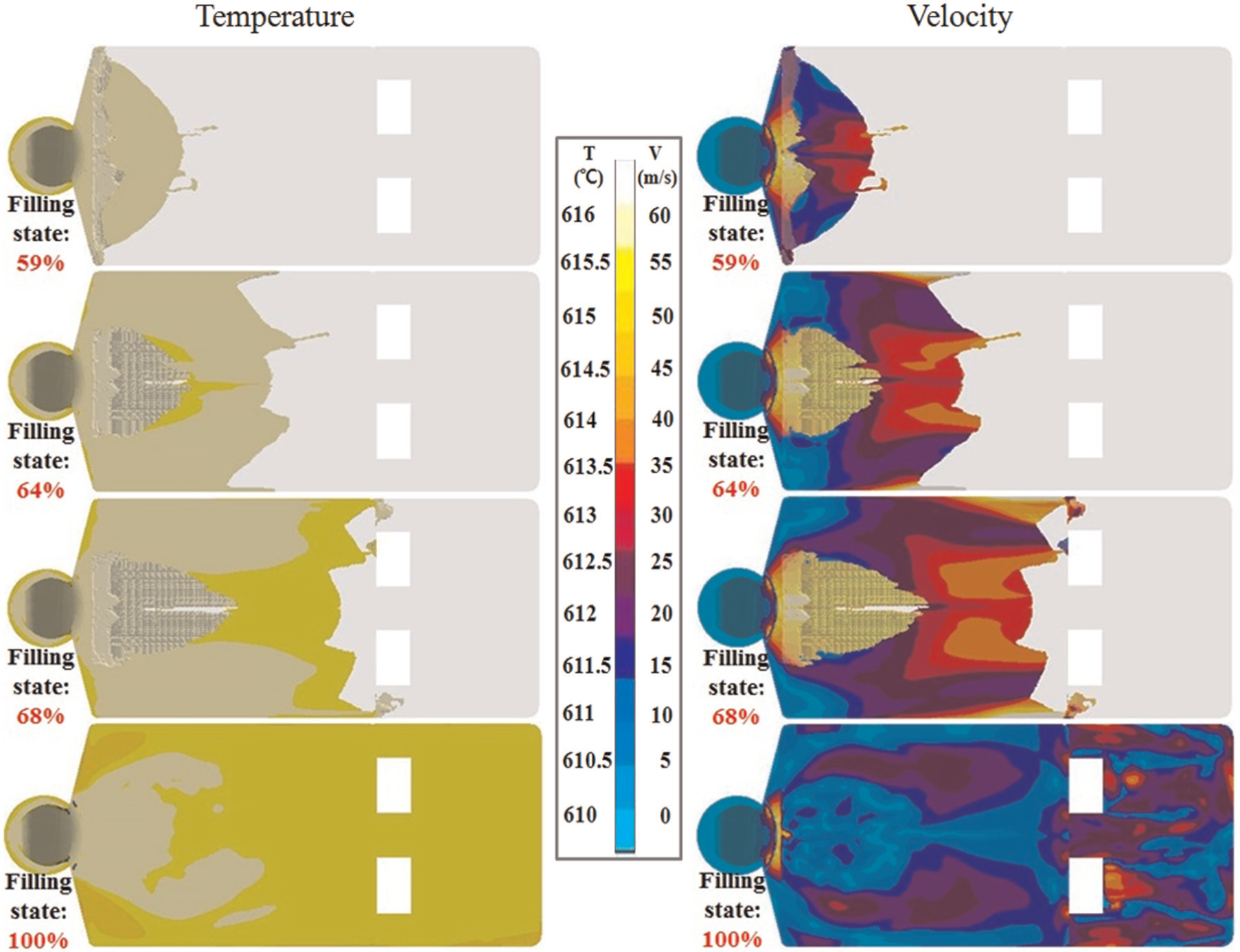
Temperature and velocity distribution of A356 Thixo alloy in MAGMA software.
The prediction of the test results through the analysis shows that the surface quality of the thin plate sample would be poor due to the occurrence of surface defects due to the flow state caused by the differences in flow velocity inside the cavity. In addition, the structure seems to have a distribution of mainly aluminium primary particles with barely any eutectic structure since the final temperature of the melt being filled was 614 °C.
Results
Microstructures of slurry
When the EMS stirring current is 100 A or greater, the centrifugal force increases due to the small inner diameter of the cup, which causes interference in the laminar flow due to the increased forces in the melt flow direction and the anti-flow direction. Figure 8 shows the microstructure of the A356 rheological material that is produced with the EMS. When the stirring current was 80 A, most of the dendrite structures were destroyed, but primary particles with rosette-like structure were distributed. When the stirring current was 100 A, all the dendrite structures were destroyed, allowing for a structure with a distribution of small, spheroid primary particles to be obtained.
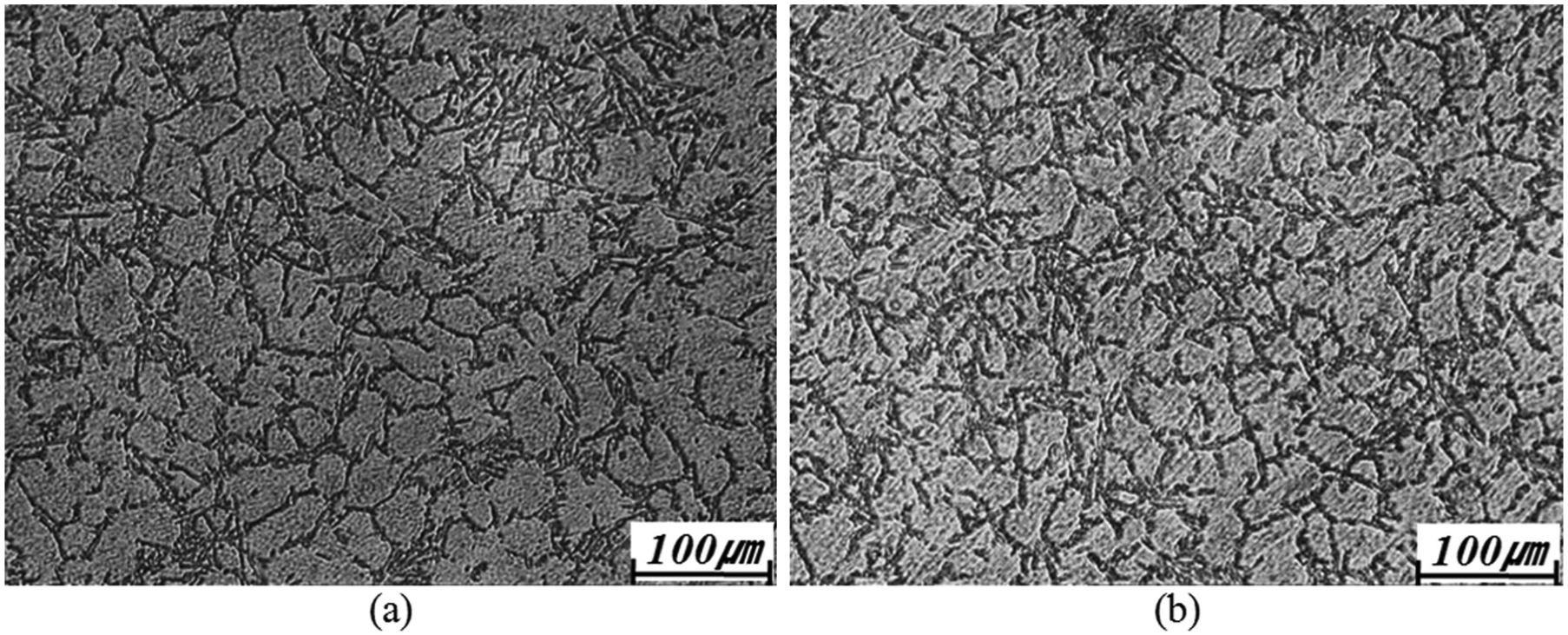
Microstructures of A356 aluminium alloy after applying EMS stirring current: (a) 80 A and (b) 100 A.
Formability, microstructures, and mechanical properties of a thin plate
Figure 9 shows the photographs of the thin plate samples that were produced by the rheo-vacuum LPDC method. In the case of the standard LPDC, the pouring temperature is 750 °C, and the gas pressure is about 0.35 bar. However, because the pouring temperature of the rheo-vacuum LPDC is about 140 °C lower than that of standard LPDC, short shots (misruns) occurred under gas pressure below 7 bar. For 9 and 12 bar, incomplete filling occurred at the end of the thin plate. A sound thin plate without incomplete filling or visible defects was fabricated under 15 bar.
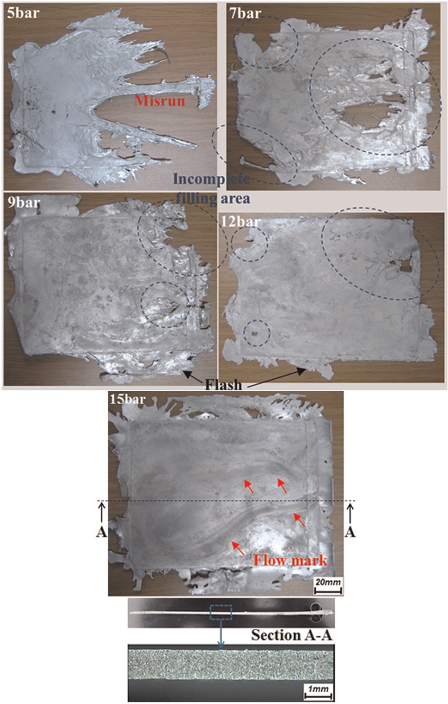
Thin plates fabricated by rheo-vacuum LPDC.
For samples produced by applying 12 bar of gas pressure, there were places with insufficient forming in areas of the gate and the cavity. In particular, there was incomplete filling at the end of the cavity. For samples produced by applying 15 bar of gas pressure, there were no areas with insufficient forming, and there was complete filling up to the overflow. As shown in the simulation results, the formation of flow marks was observed due to the difference in flow speed of the material inside the cavity. The flow of the material was induced towards the centre overflow due to the vacuum pressure. Moreover, the overall surface conditions were not good due to the uneven flow speed layers. Although the cavity can be filled with 12 bar of gas pressure due to the effect of vacuum pressure, it seems that the gas pressure is insufficient since there was incomplete filling at the end of the cavity. At 15 bar, the cavity was completely filled up to the ends through the effect of the vacuum pressure. The five thin plates fabricated by each gas pressure showed no differences in formability, with similar tendencies for fluidity.
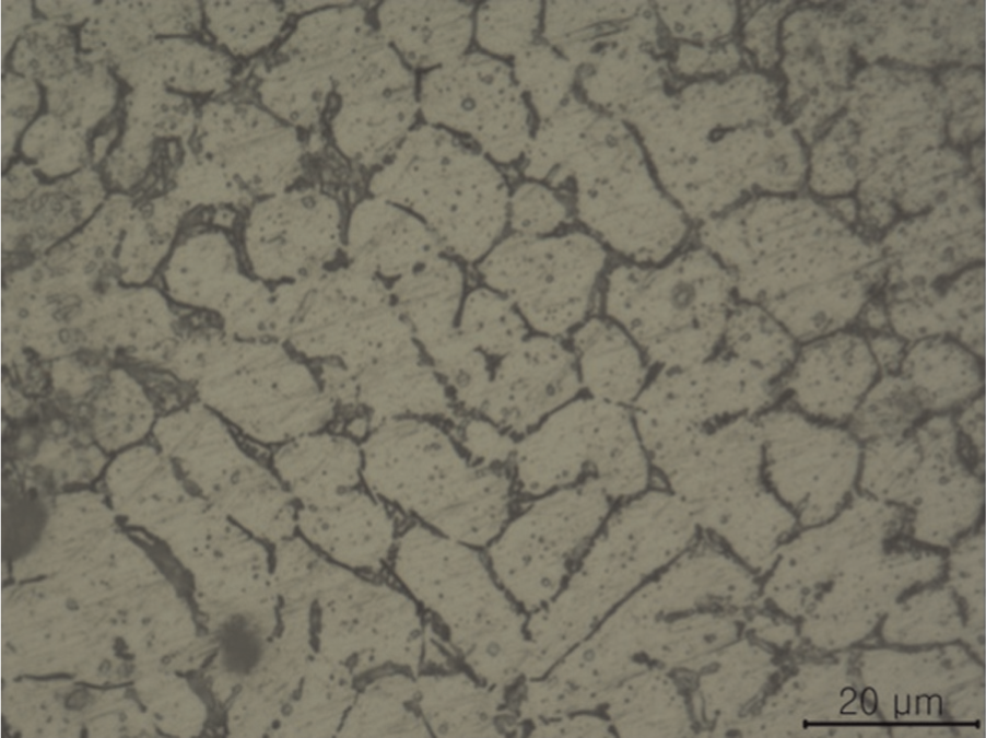
In the rheo-vacuum LPDC experiment, a rheological thin plate with a thickness of 1 mm could be constructed by applying a melt temperature of 615°C, a vacuum of 60 Torr, and a gas pressure of 15 bar. The microstructures of the samples prepared under these conditions were analysed. Figure 10 shows the microstructures for each of the areas in the thin plate sample. For the locations of the microstructure analysis, cross sections in the melt flow direction and the perpendicular direction were measured. The microstructure was measured by dividing the central area into three sections (A1, B1, and C1), as well as the side area (A2, B2, and C2), for a total of six locations.
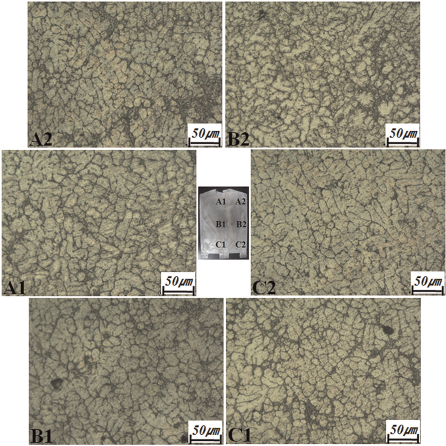
Microstructures of thin plate fabricated with gas pressure of 15 bar and stirring current of 100 A in rheo-vacuum LPDC.
As shown in the microstructure photographs for each of the areas, the ratio of eutectic structure within the structure is small, with not much difference between the positions. Also, grains with rosette-like structure are finely distributed together with the spheroidized primary α-Al particles. The shape of the primary α-Al particles was analysed in more detail, and areas A1 and C2 were observed by increasing the microscope magnification. Figure 11 shows the microstructure photographs taken by zooming into A1 and C2. The size of the primary particles is 15–35 µm, and small, irregular grains of dendritic structure are distributed together with spheroid grains. The reason why relatively smaller primary particles are distributed seems to be because the primary particles were controlled by the EMS force as the aluminium material with a solid fraction of 10% and temperature of 610 °C passed through the rasing pipe. Moreover, the reason for the ratio of the eutectic structure being low and the primary α-Al particles being mainly distributed seems to be the slow cooling after filling of the die with aluminium material with a high die temperature of 350 °C. However, it seems that the effect of EMS is minimal inside the rasing pipe since there is a high distribution of primary particles that are oval or rosette in shape throughout the entire thin plate sample. The reason for the differences with the microstructure of the slurry obtained from the EMS experiment seems to be the fast flow speed through the rasing pipe having caused the period of the stirring effect to be shorter than the 4 s that was applied in the EMS experiment. Also, the slurry was cooled in water at 610 °C, but the thin plate was cooled in air at 610 °C after injection. Therefore, it is considered that the two microstructures have differences in the particle size and the interface.
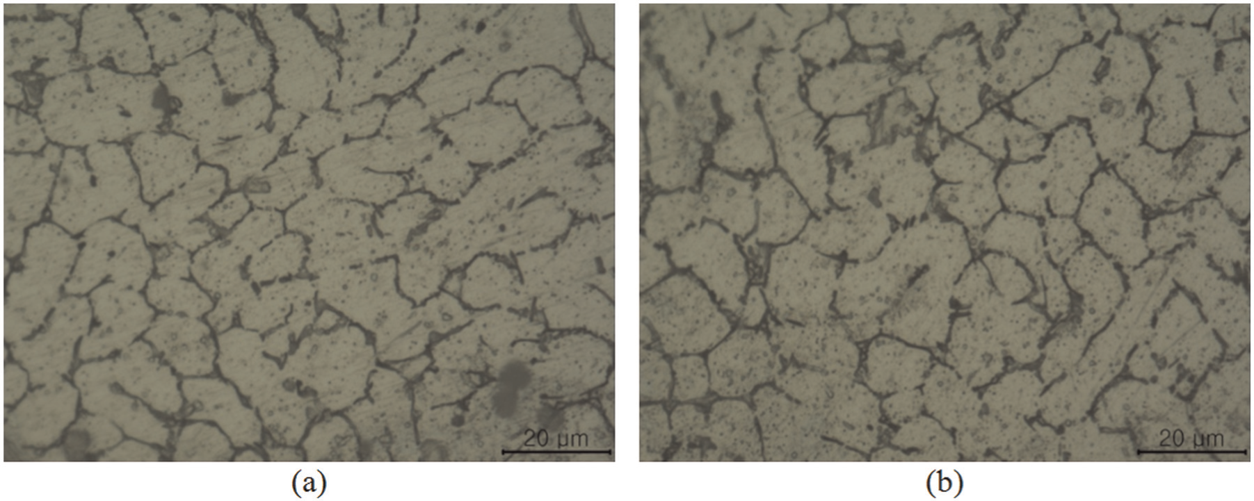
Magnified microstructures of thin plate fabricated with gas pressure of 15 bar and stirring current of 100 A in rheo-vacuum LPDC: (a) A1 and (b) C2 positions.
A tensile test was conducted by machining tensile specimens from thin plates. Figure 12 shows the machine positions for the tensile specimen and the specimen’s dimensions. The tensile specimens were prepared according to the American Society for Testing and Materials (ASTM) E8M flat standard as flat specimens with a gauge length of 25 mm and width of 6 mm. The thickness of the specimen was the same as that of the prepared samples from which they were obtained. A 25 ton Material Testing System (MTS) was used for the tensile test with a strain rate of 1 mm/min. For accurate measurements, the elongation was measured using an extensometer, which involves specimen contact. The measured tensile strength of the thin plate fabricated under a melt temperature of 615 °C, a vacuum of 60 Torr, a stirring current of 100 A, and a gas pressure of 15 bar was 120 MPa, with an elongation of 15%. The reason for the relatively low tensile strength can be predicted from the microstructure photograph of the tensile specimen in Figure 13. First, although the size of the primary α-Al particles is small at less than 30 µm, most are finely distributed with irregular aluminium grains that have oval-like shape and are interconnected. Second, as shown in Figure 13(a), the solidus region is a dense lump, which causes the eutectic structure to be unevenly distributed and to lean to one side in several areas. Third, as shown in Figure 13(b), the ratio of the eutectic structure is significantly low, so the silicon particles are not engaged in the eutectic structure, but in the solidus particles instead. For the thin plate sample made with a stirring current of 80 A, the formability was the same as the thin plate made with a stirring current of 100 A, where complete filling was achieved, and the flow mark occurred from the gate to the overflow. There was no difference in microstructures between 80 (Figure 14) and 100 A. The thin plate obtained with 80 A had tensile strength and elongation values of 115 MPa and 15.5%, respectively.
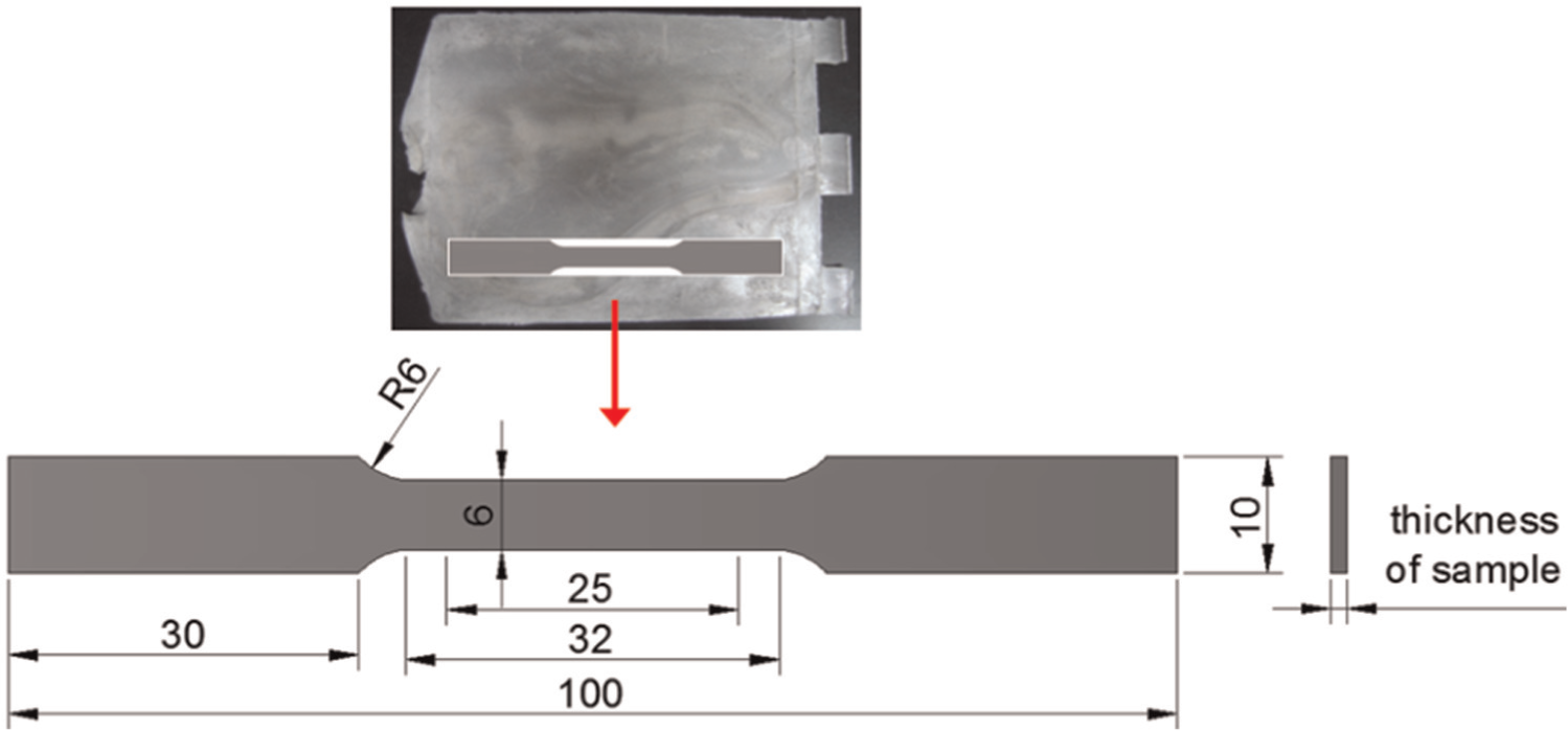
Specimen dimensions for tensile tests.
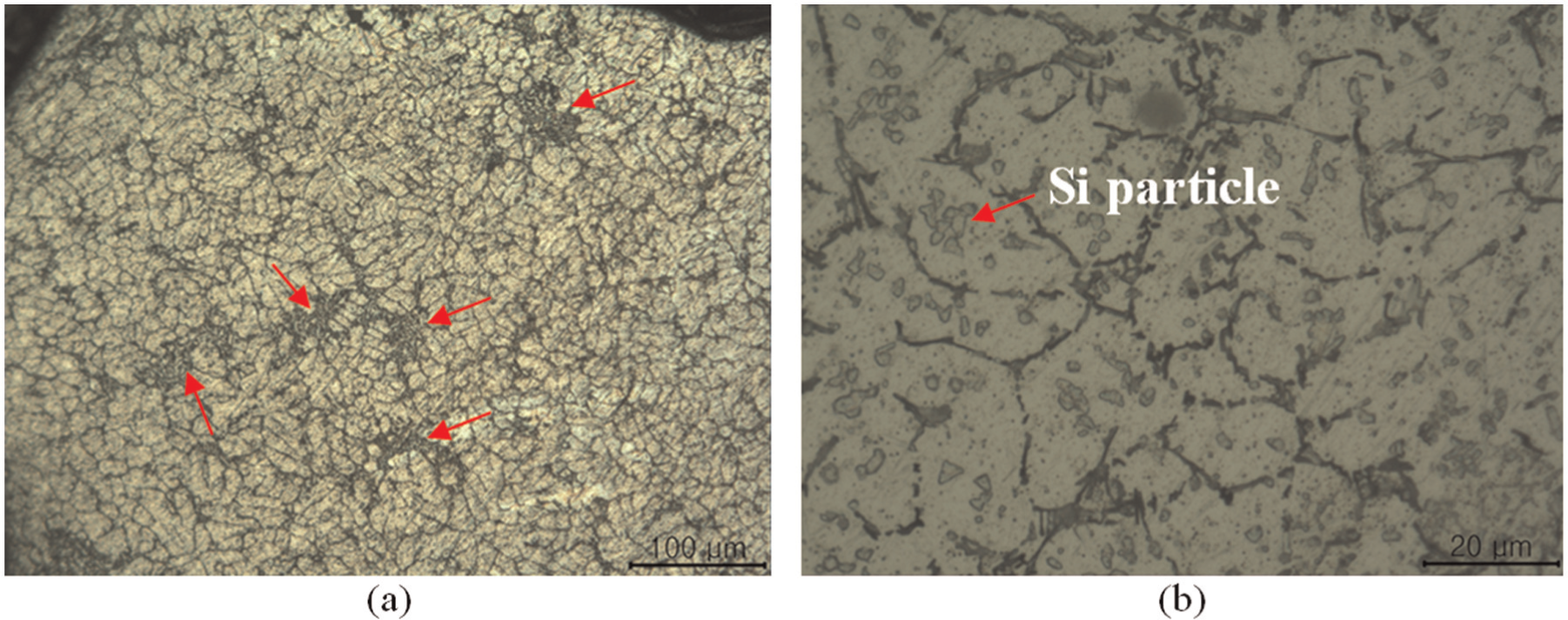
Microstructures of tensile specimen of thin plate fabricated with gas pressure of 15 bar and stirring current of 100 A in rheo-vacuum LPDC: (a) unevenly distributed eutectic structure and (b) Si particles distributed in solid particles.
Microstructures of tensile specimen of thin plate sample fabricated with gas pressure of 15 bar and stirring current of 80 A in rheo-vacuum LPDC.
The thickness and hardness of the thin plate fabricated under a melt temperature of 615 °C, a vacuum of 60 Torr, a stirring current of 100 A, and a gas pressure of 15 bar were measured for the same six locations as in the microstructure analysis. Figure 15 shows the hardness and thickness values for the six places of the thin plate sample. Vickers hardness tests were conducted with the application of a 50 g load. The hardness was measured five times for every position, and the maximum, minimum, and average values (■) were expressed. A micrometre was used to measure the thickness. The hardness measurement for gate area A where the melt enters and area B at the centre of the cavity was 65–66 HV, while that of area C was 61 HV. The die was machined with a tolerance of 0.05 mm. The actual thickness of the die cavity was 1.05 mm. Therefore, the thickness of the thin plate samples was 1.02–1.05 mm. Along the melt flow direction, the centre region (A1, B1, and C1) is a little thicker than the side region (A2, B2, and C2). As shown in the simulation result, the centre of the cavity is filled last due to the high-speed layer during the period of the cavity being completely filled. As such, the sides of the cavity solidify first before the centre region, and the centre region becomes thicker than the sides since it continues to receive the melt. Also, as shown in the sample photograph in Figure 9, flash defects occurred, in which material spills out between the upper and the lower die. This made the thickness non-uniform. The sides of the thin plate are thinner than the centre of the thin plate because the material at the sides of the cavity spilled out due to the relatively high pressure.
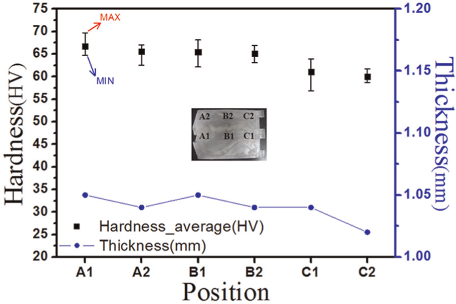
Hardness and thickness of thin plate with gas pressure of 15 bar and stirring current of 100 A in rheo-vacuum LPDC.
The reason for the low hardness at point C at the end of the cavity seems to be the low effects of the argon gas pressure. Just as there was insufficient filling at the end of the cavity for the samples formed at 12 bar of gas pressure, it seems that the density at the overflow part is low even if the whole cavity is filled with 15 bar of gas pressure.
Conclusion
A rheo-vacuum LPDC was developed, and thin plates with a thickness of 1 mm could be produced using A356 aluminium material. The test results are as follows:
Unlike the established LPDC process, a vacuum pump was connected to maintain a vacuum state inside the die, and an EMS was installed on the outside wall of the rasing pipe in order to control the grains of the aluminium material.
Through mild filling analysis, the rheology behaviour of the material inside the die during the actual rheo-vacuum LPDC could be observed. Due to the flow mark defect of the sample, filling appearance similar to that in the analysis results could be observed.
Finished products without incomplete filling could be produced by applying a melt temperature of 615 °C with a solid fraction of 10%, 15 bar of argon gas pressure, 60 Torr of vacuum pressure, 80 A of stirring current, and a die temperature of 350 °C.
The microstructure of slurry made with 100 A stirring current of EMS has no dendrite structure. The microstructure of the thin plate made with 100 A stirring current differed from that of the slurry with 100 A stirring current due to the stirring time and the cooling method.
There was not much difference in the microstructure of the thin plate samples produced according to the location. There was little eutectic structure with primary aluminium grains of 30 µm or below mostly distributed due to the effects of stirring. The thickness was 1.02–1.05 mm, which is more than the die cavity thickness, and the hardness was 61–66 HV.
Most are primary α-Al particles and Si particles are engaged in the solidus particles and which is why the mechanical properties of thin plate fabricated under melt temperature of 615 °C, stirring current of 100 A, and gas pressure of 15 bar were 120 MPa with elongation of 15%. The thin plate samples made with stirring current of 80 A, the formability, microstructure, and mechanical properties were the same as thin plates made with stirring current of 100 A.
Footnotes
Declaration of conflicting interests
The authors declare that there is no conflict of interest.
Funding
This study was supported by the National Research Foundation (NRF) of Korea Grant and funded by the Korean government (grant No. 2013R1A1A2062759). This study was also supported by the Human Resources Development Grant of the Korea Institute of Energy Technology Evaluation and Planning (KETEP), funded by the Korean government Ministry of Knowledge Economy (no. 20104010100540) and the Korea Research Foundation (KRF) Grant, and funded by the Korean government (MEST) (grant no. 2012-0001204).