
Abstract
Advanced high-strength steels are being used widely in automotive industry to achieve lightweight construction and fuel efficiency. During advanced high-strength steel blanking, the die components have to sustain higher pressure, and this may result in some problems such as chipping, cracking, galling and severe die wear, which has a great effect on the die life. This study aims to investigate the wear resistance performances of five die materials (carburized 4Cr13, conventional SKD11, Caldie, A2 and tungsten steel D60) using a featured blanking die setup combining five different die materials. The surface topography and microstructure of punching die materials are measured by optical profilometer and microscope. Based on the measured results, the specified wear rate and worn profiles of die inserts are obtained and compared. It is demonstrated that Caldie and A2 have higher wear resistance performance than SKD11 and 4Cr13. Moreover, the experimental results display that the most severe wear locations occur at the interfaces of straight lines and circular arcs.
Introduction
Owing to fuel economy, environmental and safety concerns, most auto makers have passions in increasing the use of advanced high-strength steels (AHSSs) in structural components. Comparing to mild steels, AHSS sheet materials have higher strength and better crash performance. More importantly, the use of AHSS offers significant advantages such as weight reduction without sacrificing safety and durability, saving of fuel consumption and reduction of hazardous emissions.1,2
However, in the process of AHSS sheet metal blanking, higher contact stress may occur between the tools and the workpieces, which results in increased amount of tool wear, chipping and galling, compared with blanking traditional mild steel sheets. 2 Accordingly, insufficient product quality and unpredicted cost increase dramatically. To assure robust mass production of AHSS stamping, it is imperative to look for the potential alternative die materials suitable for punching AHSS sheets. As it can also be seen, die wear is a dynamic process combining effects of sheet surfaces, material properties, process performances, stress/strain, tool geometry and lubricant and so on. 3 Many researchers have developed some methods and experiments to compare alternative die materials for forming of AHSS sheets.
Convenient and low-cost pin-on-disc test4–6 device has been applied widely, and the pin is basically smaller than 5 mm diameter and continuously contacts with the worn and scratched sheet blank surface. Alinger and Van Tyne 7 utilized bending-under-tension test to evaluate the tribological characteristics of several forming die materials and concluded that the tungsten carbide die material has the best performance with respect to the lowest frictional coefficient and highest resistance for anti-wearing among the tested die materials. Cora and Koç 1 developed a robot-based die wear test system by using bullet-type die sample moving along the untouched DP600 sheet surface over multiple tracks and compared the wear performances of six different uncoated die materials with the conventional tool steel AISI D2 die material. Podgornik et al. 8 employed a load-scanner test setup consisting of a stationary test cylinder and a rotating cylinder that are made of die material and the interesting sheet material, respectively, in order to evaluate galling behavior of the heat-treated tool surfaces. In this test, the scanned contact surfaces in each cycle are retouched comparing to the new touching in the real punching/blanking process. Similarly, the repeated contact tracks on the same sheet material surface were used in the twist compression test (TCT),9,10 and it was proved out to be suitable for comparing the test variables rather than obtaining an exact wear volume loss. 11 Except for the previously mentioned tests, there are some other wear testing methods, such as U deep drawing,12,13 draw bead, 14 strip drawing,15–17 strip pulling, 18 combined draw bead, strip pulling19,20 and bending under tension or radial strip drawing. 21 All these wear test methods seem closer to real drawing process rather than punching/blanking process. Certainly, there is big difference between drawing process and blanking/trimming process; die wear mainly happens at round corners during drawing process, while die wear mainly happens at the sharp edges on the punch and the die during blanking/trimming, and the sharp load history may also bring shock to the stress-concentrated edges, which very often causes chipping. Therefore, it seems necessary to develop an experimental setup which can be used to evaluate the wear resistance performances and chipping/crack of different die materials under real blanking conditions.
In this study, a new experimental setup for blanking AHSS sheet metal is developed, and the primary goal is to benchmark performance of the alternative cold working die materials in AHSS sheet blanking process. Wear characteristics and chipping are evaluated through blanking tests reaching 40,000 strokes in total. Five popular die materials are investigated and characterized in wear resistance, worn profiles, chipping and edge quality of the blanked part. The comparisons of these die materials offer an insight into the behavior and the magnitude of tool wear on the tool surfaces and provide possible alternatives for die engineering.
Experiment of DP780 blanking
Blanking die setup
The gap between die edges has an important effect on the edge quality of blanked parts. Based on this, two gaps including 6% and 4% sheet metal thickness are employed in the blanking die, and two radii including 5 and 10 mm are designed on the workpiece. Therefore, an X-shaped workpiece is developed and shown in Figure 1 with configuration and blanked part. The punch and die are shown in Figure 2, and their setup and mounted inserts are shown in Figure 3. In the blanking setup, there are four straight-line edges (#2, #3, #6 and #7) with clearance 6%, and the rest are all designed to clearance 4%, especially four straight-line edges (#1, #4, #5 and #8) with clearance 4%, as plotted in Figure 2. In this study, the blanking tests of DP780 made by Bao steel are carried out on a 100T mechanical press. The blank holder pressure is applied by eight high-strength springs that are linked together, which could provide evenly distributed pressure over the blank holder surface. The die materials for punch inserts are ferrite–martensite stainless steel 4Cr13, Caldie made in Sweden, JIS SKD11 made in Japan and A2 also made in Sweden. Corresponding to the die materials for punch inserts locating quadrant, the die materials for die inserts are 4Cr13, Caldie, JIS SKD11 and tungsten carbide alloy D60. Since it is difficult to make D60 as thickness of 8 mm jointed with the base material in the laboratory, an alternative die material A2 is applied to the quadrant opposite to the D60.
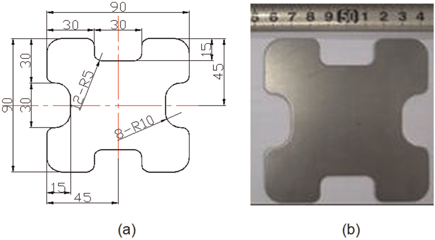
(a) Configuration of workpiece and (b) blanked part of DP780.
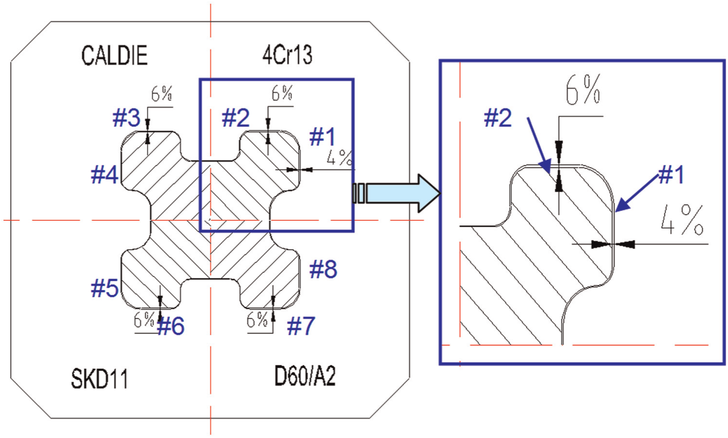
Configuration of die with clearance 6% and 4%.
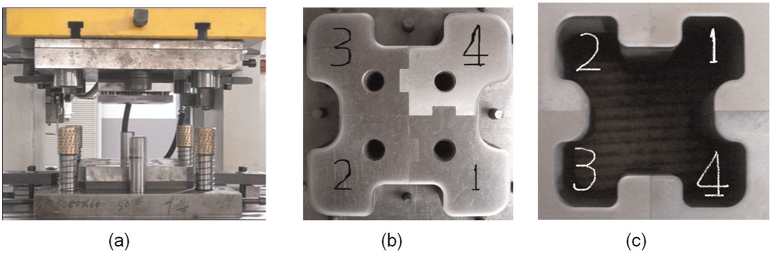
(a) Blanking die setup, (b) mounted punch and (c) mounted die.
Materials used in the experiment
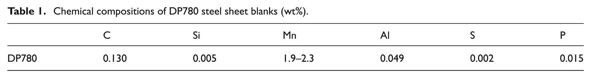
Sheet blank used in the test is DP780—a typical AHSS with 1.4 mm thickness, and it contains ferrite to improve the formability and ductility and martensite to improve the strength. The chemical composition of DP780 is given in Table 1, and its average hardness value for DP780 is examined as 260HV1.
Chemical compositions of DP780 steel sheet blanks (wt%).
During the blanking test, five different die materials are tested to compare their wear resistance performance. Except the tungsten carbide D60, the chemical compositions of the four other tested die materials are shown in Table 2.
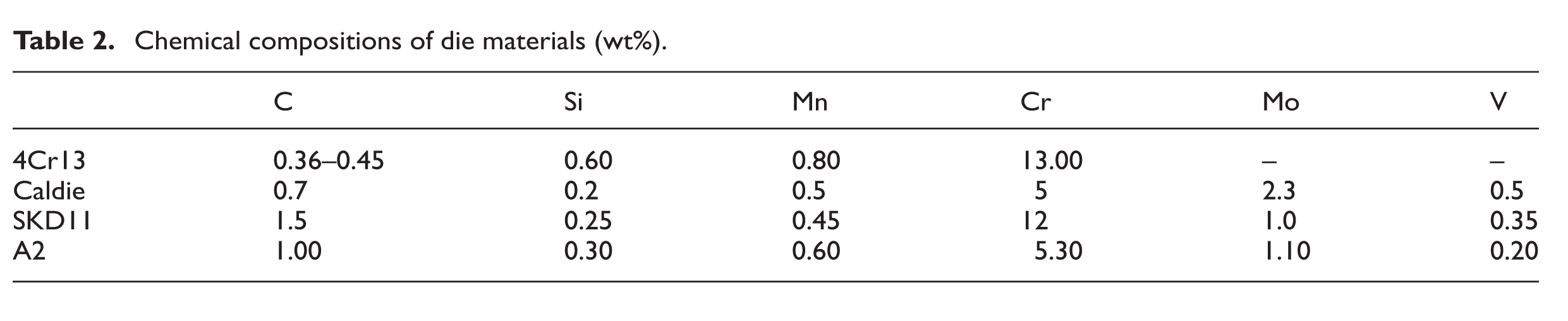
Chemical compositions of die materials (wt%).
During the blanking process, the hardness and surface roughness values of the die materials have significant influences on the coefficient of friction and wear resistance.
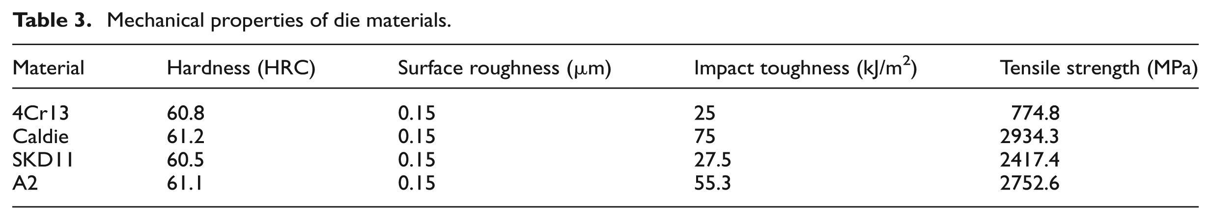
Therefore, the hardness values of die materials are specified to be around HRC60 after heat treatment and the roughness values are specified to be around 0.15 µm. The surface hardness values are measured based on metallic Rockwell hardness tests (ISO 6508-1:1999) and the surface roughness values of the inserts are evaluated from three-dimensional (3D) optical profilometer. In addition, the impact toughness values of four die materials by Charpy V-notch pendulum impact tests (ISO 14556-2000) varied from 25 to 55.3 kJ/m2. The detailed mechanical properties of the four other tested die materials are shown in Table 3.
Mechanical properties of die materials.
As a carburized high-chromium low-carbon stainless steel, 4Cr13 has been used to make medical tools. In this research work, it is used to make the die component due to its advantage in avoiding high-temperature quenching-induced deformation. 4Cr13 is carburized in a carburizing furnace with an initial hardness of 229HB; the carburization route is as follows: first low-pressure carburized for 3 h at 900 °C, then water or oil quenched and finally tempered for 2 h at about 200 °C. Afterward, the hardness can reach 60HRC. The depth of carburized layer is about 0.5 mm and carbide particles are uniformly distributed, as shown in Figure 4(a).
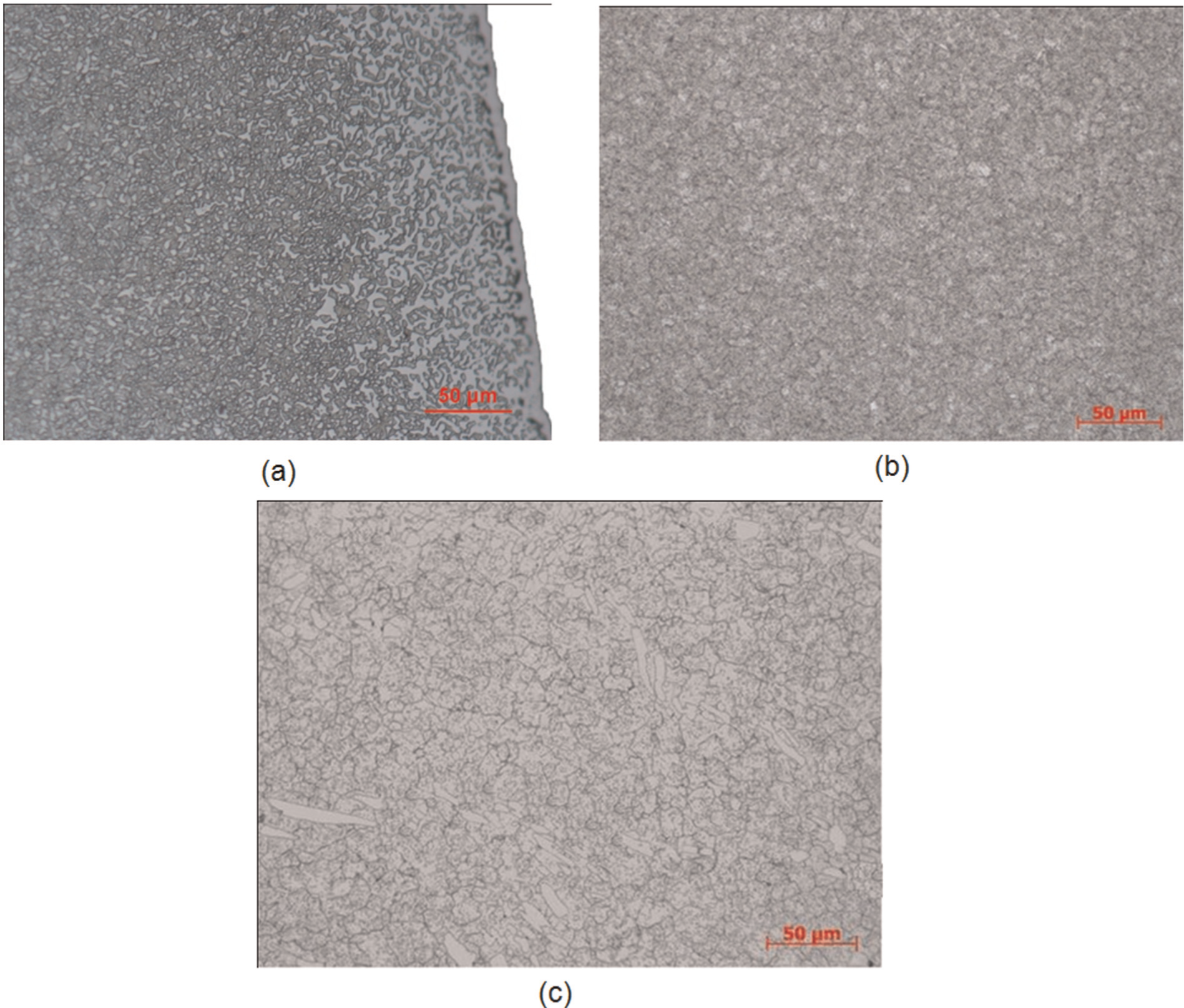
Microstructure of tested die materials: (a) 4Cr13 after surface carbonization, (b) Caldie and (c) SKD11.
Caldie is also a chromium–molybdenum–vanadium alloyed tool steel, characterized for its good wear resistance and very good chipping and cracking resistance. In this study, Caldie is heated up to 1025 °C (1875 °F) and gas quenched in vacuum furnace and tempered twice at 525 °C (975 °F) for 2 h to reach 60HRC, and the microstructure is shown in Figure 4(b).
As a calibrated material for comparing wear resistance performance of the tested die materials, SKD11 consisting of chromium, molybdenum and vanadium has been widely used in the AHSS stamping die and is hereafter considered as baseline. The material is heat treated by oil quenching at 1025 °C and air tempered at 500 °C to get the hardness as of 60HRC, and the microstructure is shown in Figure 4(c).
AISI A2 is an Uddeholm tool steel22,23 and can be regarded as universal cold work steel, offering an excellent combination of good wear resistance and high toughness. In this study, AISI A2 is heated up to 1560 °F (850 °C) and held for 2 h, then cooled slowly in the furnace at a speed of 20 °F (10 °C) per hour to 1200 °F (650 °C) and then exposed in the air, making AISI A2 hardened and tempered to 61.1 HRC.
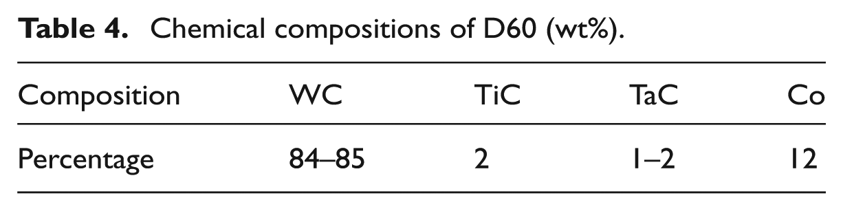
Especially, to enlarge the visible range of wear resistance performance of die materials, a tungsten carbide alloy D60 is used in one quadrant of the testing die. The grain size of tungsten carbide (WC) as hard phase is around 1 µm and the weight range of cobalt (Co) as binder phase is about 12%, as shown in Figure 5. The typical chemical compositions and detailed mechanical properties of D60 are shown in Tables 4 and 5, respectively.
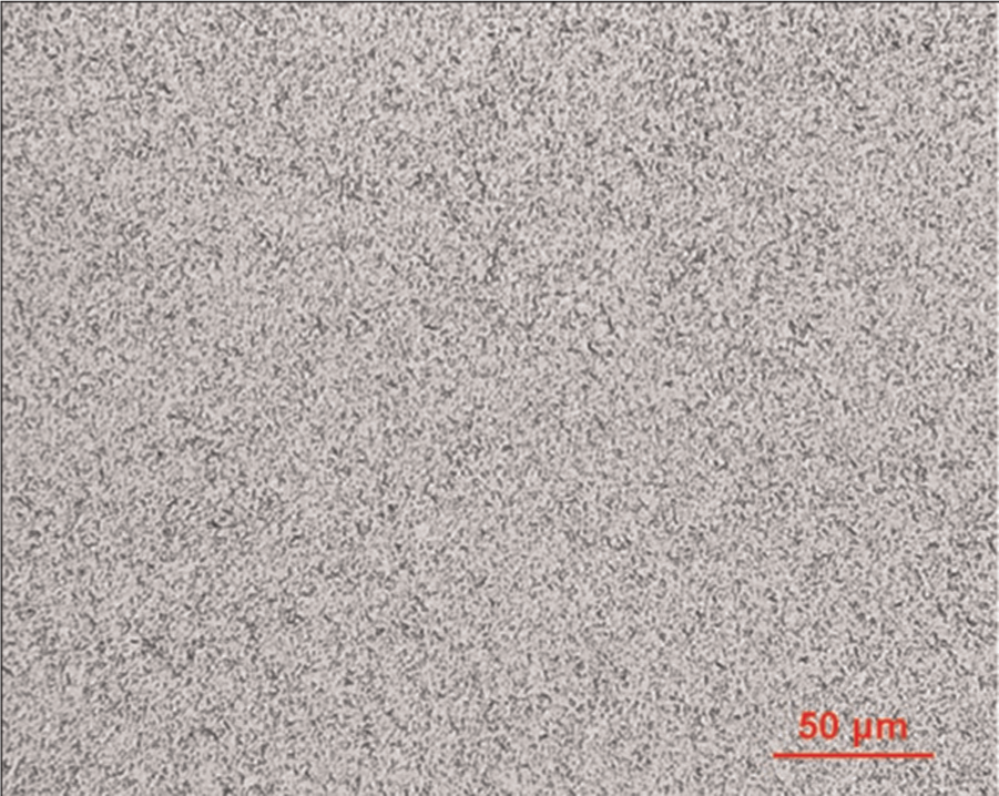
Microstructure of tested D60.
Chemical compositions of D60 (wt%).
Material properties of cemented carbide D60.
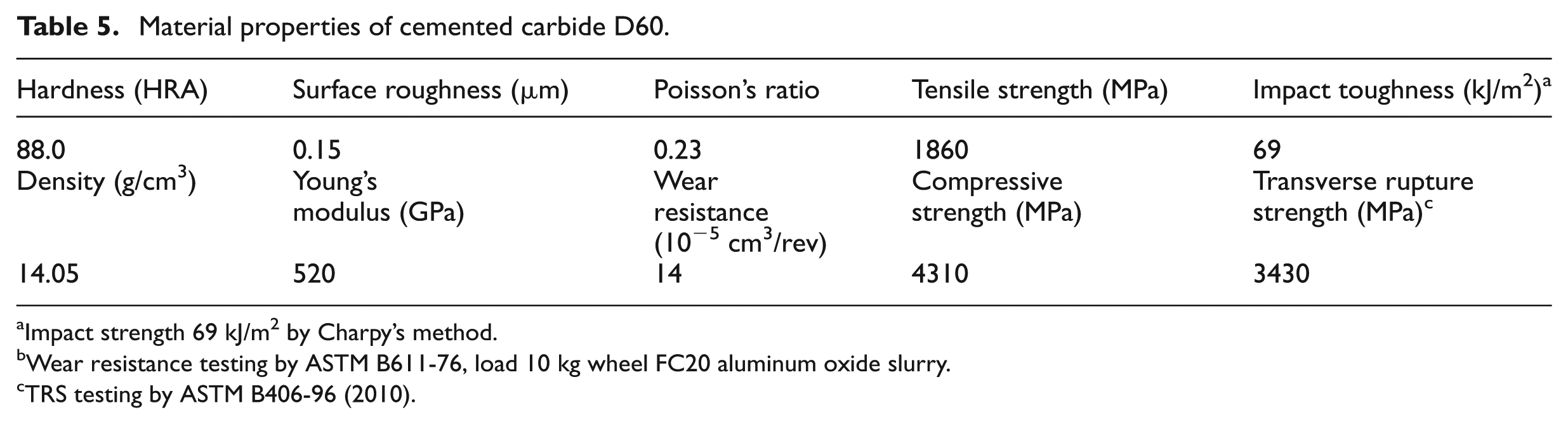
Impact strength 69 kJ/m2 by Charpy’s method.
Wear resistance testing by ASTM B611-76, load 10 kg wheel FC20 aluminum oxide slurry.
TRS testing by ASTM B406-96 (2010).
Results and discussion
Specified wear rate
After wear punching tests, the worn profiles of each die insert were measured with a 3D non-contact multi-sensor optical profile meter (OGP ZIP-250, high accurate surface profiler). For each worn profile whether straight line or circular arc, evenly five sections were scanned, and the five scanned profiles were collected and fitted to one profile. The fitted profiles for straight lines (marked #1–#8 in Figure 2) with clearance 6% thickness and 4% thickness are shown in Figure 6. Thus, the worn loss area can be easily obtained by comparing the worn profile with the initial machining profile (Figure 7), and the wear volume for each worn profile can be further calculated by multiplying the worn loss area with the length of the profile, and the wear area of the eight straight-line edges labeled in Figure 2 is shown in Table 6.
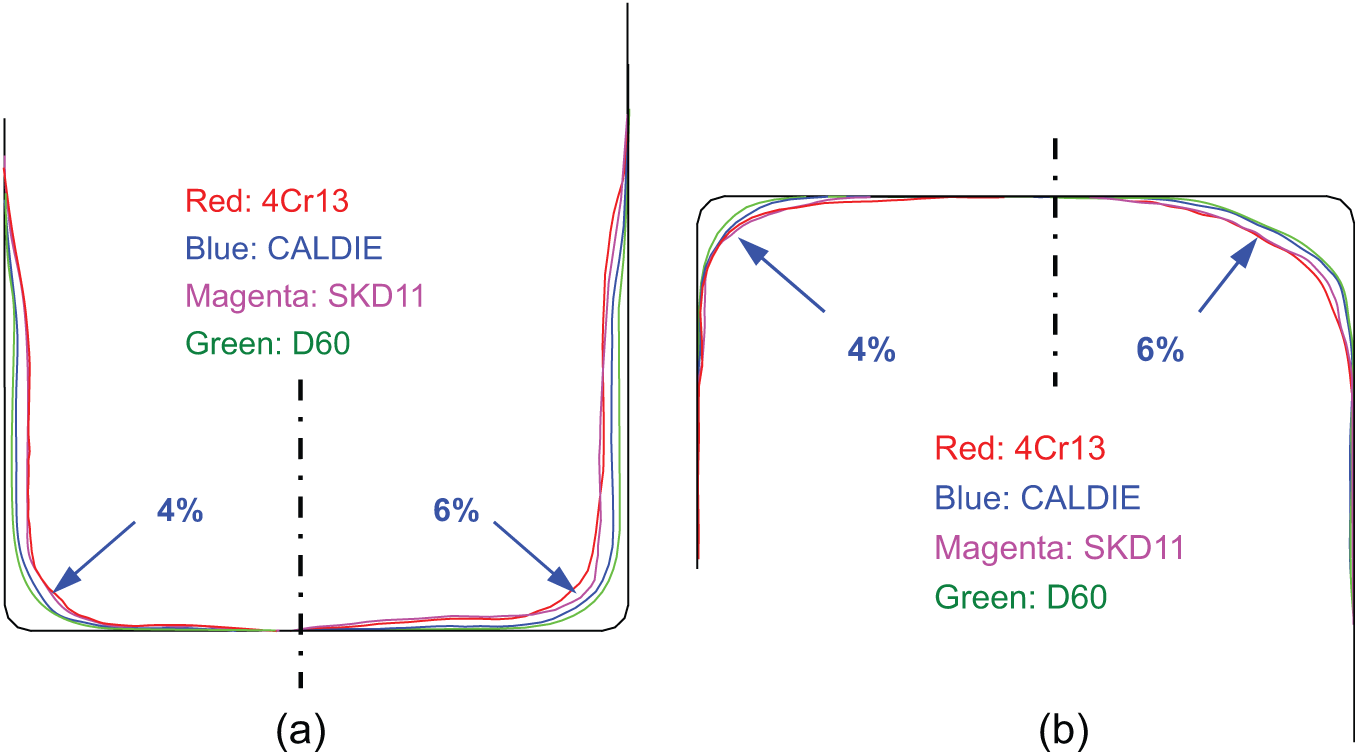
Fitted worn profiles of punched die materials: (a) punch inserts and (b) die inserts.
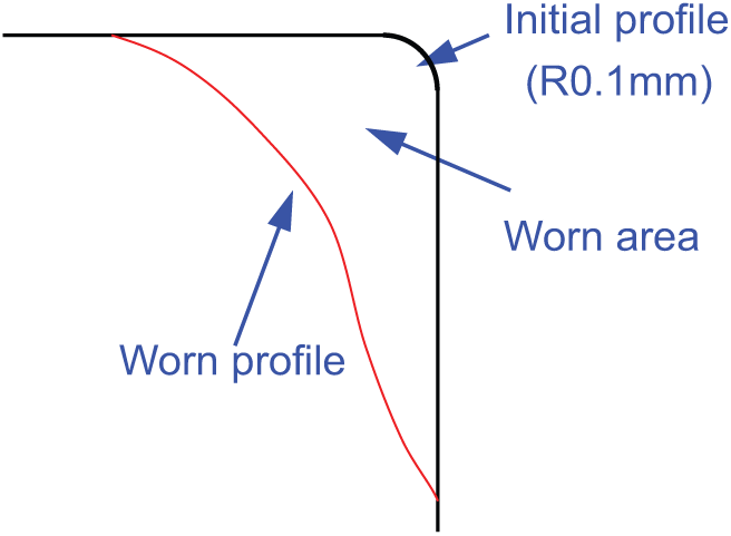
Calculation of wear loss area.
Worn area and specified wear rate of punched die materials.
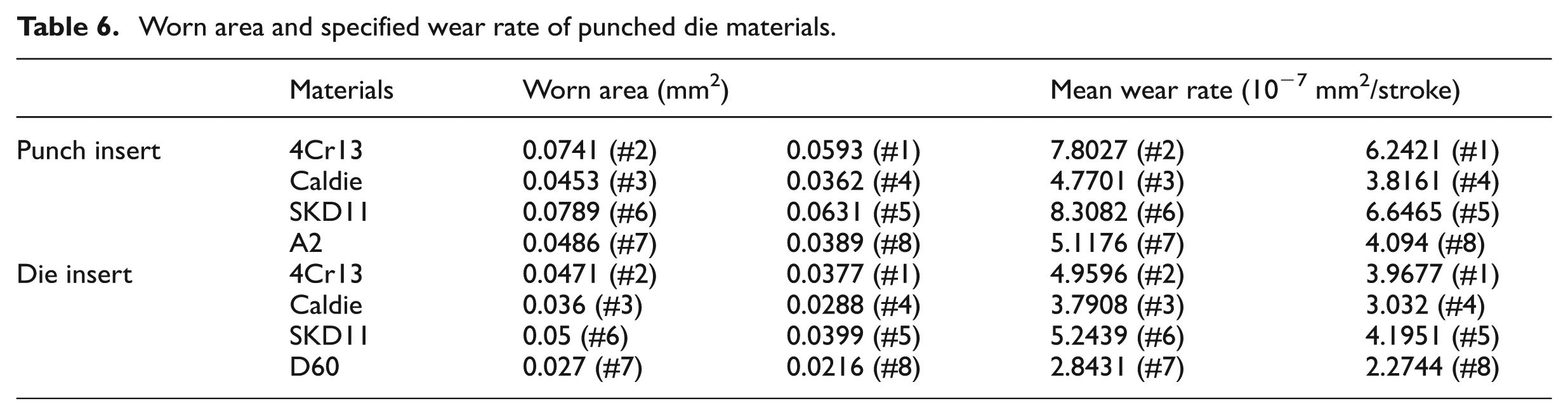
In the literatures,3,9,24 to evaluate and quantify the wear resistance performances of materials, many wear models have been developed by researchers. One of the popularly used parameters comparing the wear performance of the materials is the wear rate that is expressed as the following formula
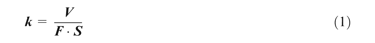
where
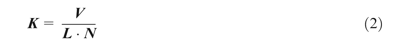
where
The specified wear rates for the eight straight-line edges are also shown in Table 6. From Table 6 and Figure 6, it can be seen that the straight lines with 6% clearance suffer more wear loss area than the straight lines with 4% clearance because the sheet metal in the wider clearance suffers more severe plastic deformation, which makes the slide distance between the sheet metal and die edges longer evidently and generates more wear loss volume based on the wear theory (equation (1)). For all tested die materials, it is found that die edges made of carbide alloy D60 have the least wear loss and the best wear resistance performance. However, the wear resistance performances of SKD11 and 4Cr13 are the worst ones, and Caldie and A2 are in the middle of them.
Wear resistance performance
Microscopic examinations were employed for all die insert edges including circular arcs and straight lines after punching tests. Specifically, the micrograph maps of the straight lines with 6% clearance and the fillets with radius 10 mm are shown in Figure 8(a)–(h). It is found that the punch inserts are worn more severely than the die inserts in the same quadrant due to the longer contact distance resulting from the reciprocated movement between the punch and the blank. Moreover, the punch inserts of SKD11 and 4Cr13 are worn more heavily than the others of A2 and Caldie. Absolutely, D60 is the best one among the tested die materials due to its intensive microstructure distribution. From the comparisons of die edge features such as straight lines and circle arcs, it is shown that the most severe wear loss happens at the intersections of straight lines and circle lines because the maximal stresses occur there in each quadrant. From Figure 8(a)–(h), it can also be seen that there are many chippings at die edges, and the mechanism and comparison of chipping will be illuminated in detail in the following passage.
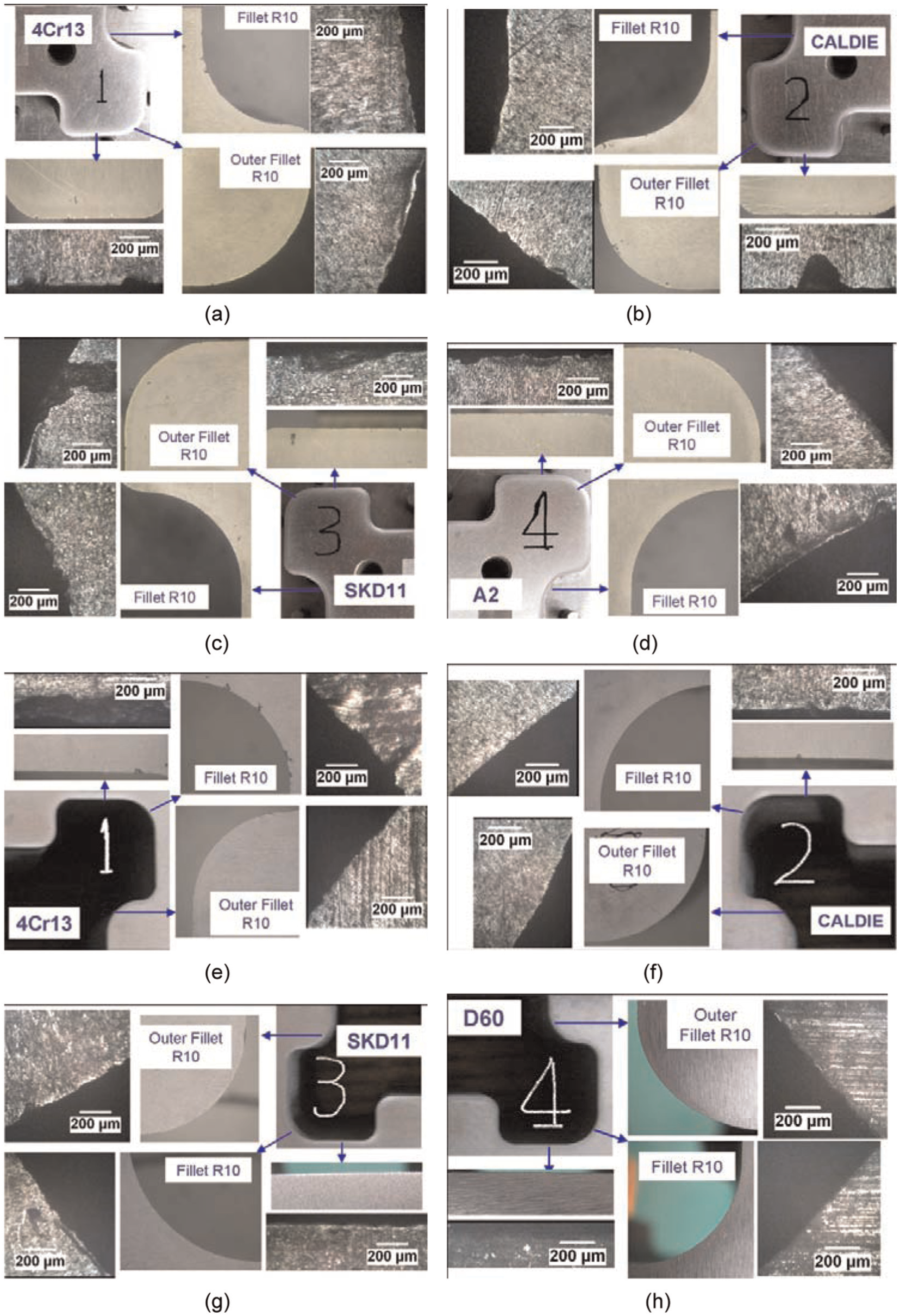
Micrograph maps for die inserts after punching tests: (a) 4Cr13 punch insert, (b) Caldie punch insert, (c) SKD11 punch insert, (d) A2 punch insert, (e) 4Cr13 die insert, (f) Caldie die insert, (g) SKD11 die insert and (h) A2 die insert.
In addition, the complete 3D surface textures along the die edges located at the middle of outer fillet with radius 10 mm were also obtained by non-contact 3D optical profilometer with accuracy of 1.0 nm. As shown in Figure 9(a)–(h), the measured topographical surfaces are shown within the selected die edges in plotted size 0.2 mm × 0.2 mm, and both the smooth surfaces and the chipping/cracking of worn edges are measured. From Figure 9(a)–(h), among these five selected die materials, it can be concluded that the tungsten carbide D60 has the strongest wear resistance performance, and SKD11 has the worst wear resistance performance because of its big grain size and the lower coalescence force. 1 4Cr13 has the most severe chipping due to its big carbide size and unorderly distribution of carbide generated from carburizing process. The size of chipping is around 50 µm × 50 µm × 50 µm for 4Cr13 and SKD11 (Figure 9(a) and c)) basically, which has a great agreement with the size of carbide shown in Figure 4(a) and (c).
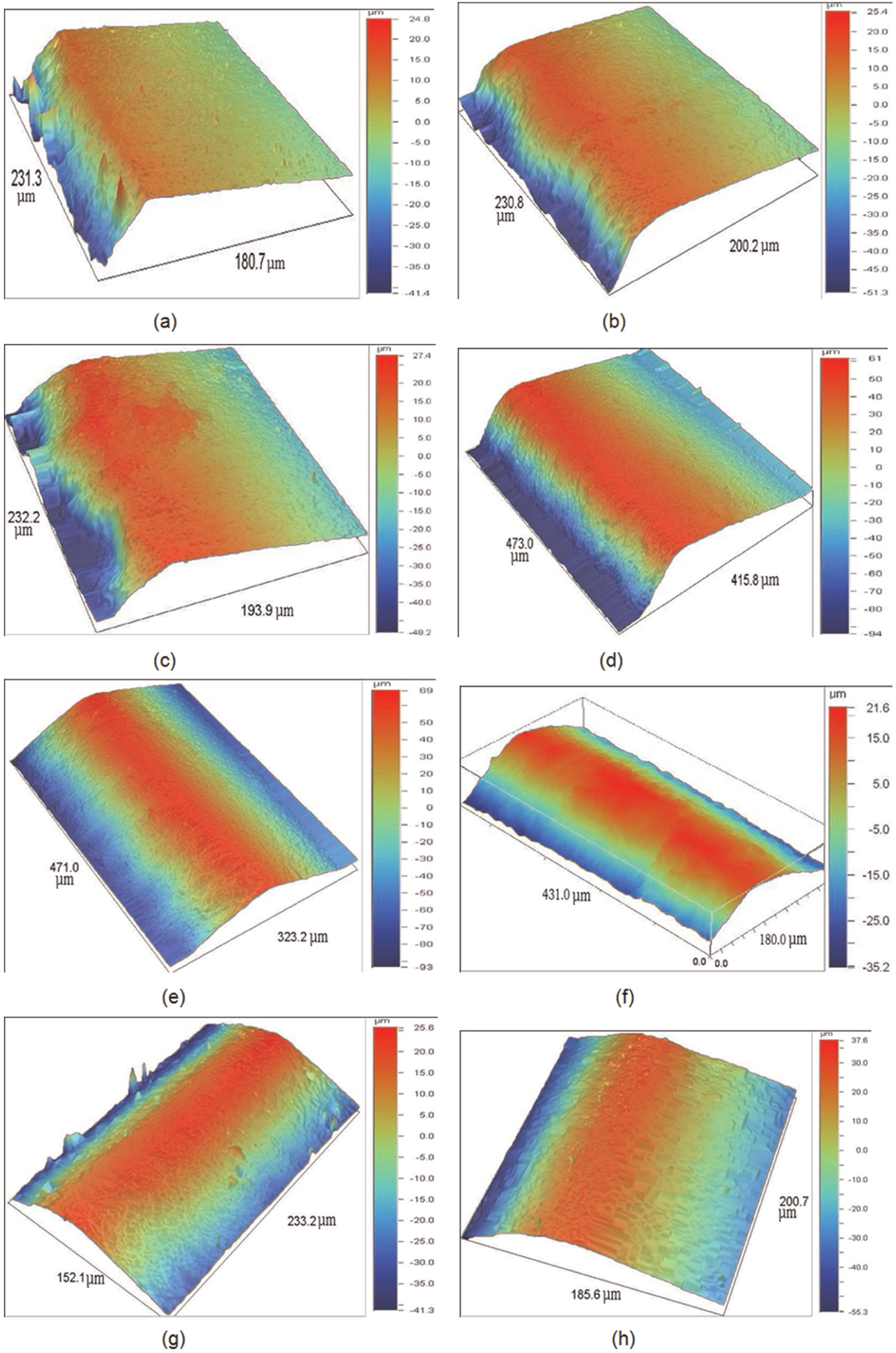
Three-dimensional optical profilometer measured surface of die inserts: (a) 4Cr13 punch insert, (b) Caldie punch insert, (c) SKD11 punch insert, (d) A2 punch insert, (e) 4Cr13 die insert, (f) Caldie die insert, (g) SKD11 die insert and (h) D60 die insert.
Chipping
During punching/trimming process, higher stresses are mainly distributed around the sharp edges, and this may result in stress concentration. Punching/trimming is typically a dynamic process with shock when the punch touches the sheet metal and the sheet metal is separated by the tool, and non-uniform distribution of the material properties on the die components will inevitably trigger the weakest positions to deform plastically and crack, and finally the chipping is generated. Theoretically, the occurrence of chipping depends on mechanical fatigue or thermal fatigue, and some parameters such as applied load, load interval and material microstructure play an important role in the appearance of chipping. From the experimental examinations shown partly in Figures 8 and 9, chippings can be observed clearly on the edge surface of die inserts except tungsten D60, and it can be summarized that the features of circular arcs cause more chippings than the ones of straight lines for the tested die edges with 4% clearance. Higher stress distributions occur at the edges of circular arcs during the process of punching, which results in more chipping appearance based on the fatigue mechanism. The straight lines with 6% clearance result in more chippings than the straight lines with 4% clearance because the sheet metal locating the 6% clearance undergoes more severe plastic deformation, which makes the die edges suffer longer applied loads and generates more chippings based on the mechanism of chipping appearance. It is also found that there are more chippings at the punch edges comparing to the die edges in the same quadrant. Because the punch inserts sustain longer applied load time due to its reciprocated contact with sheet during the process of punching. Furthermore, Caldie has better chipping resistance performance than 4Cr13 and SKD11 due to its fine carbide grain. Tungsten D60 does not get chipping on the die edge because of its best grain size in 1 µm.
Blanked edge quality
In the cross section of blanked workpiece, there are four obvious characteristic areas such as rollover area, burnish area, fracture area and burr, as shown in Figure 10 with blanked edge formation. In this study, a novel method drawing average line in the front view of cross section (Figure 11 (left)) is employed to measure the lengths of the four characteristics in the cross section, instead of evaluating random sectional view of workpiece (Figure 11 (right)).
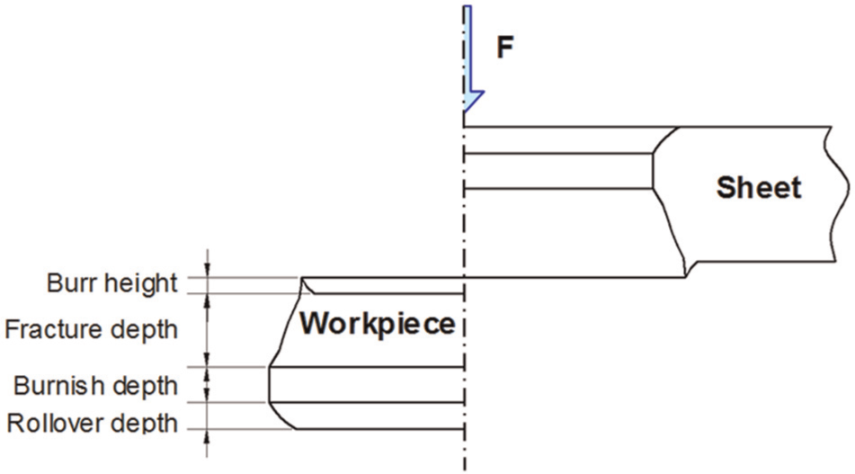
Schematic of punched edge formation.
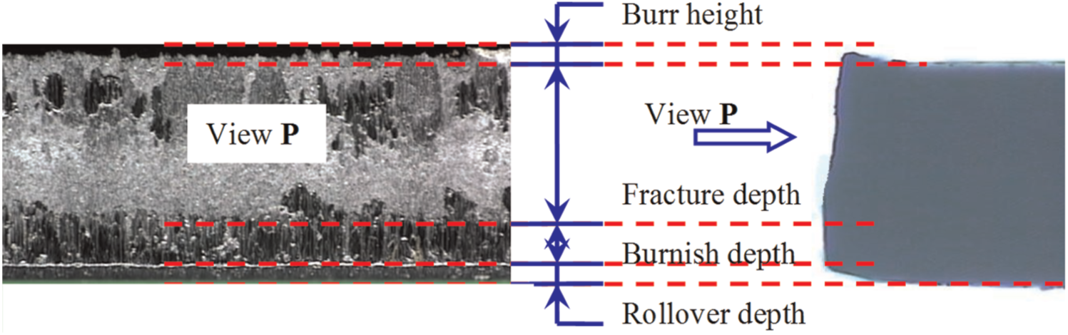
Schematic of tested edge quality.
The front views of the straight punched edges of the 40,000th workpiece are observed and symmetric locations with clearance 6% from the four quadrants are displayed as shown in Figure 12. It can be seen that the boundaries between fracture area and burnish area blanked by D60/A2 and Caldie are more regular and orderly than the ones blanked by 4Cr13 and SKD11. With the increase in chipping and wear volume loss, the die edges of 4Cr13 and SKD11 become irregular and worn, which results in larger and uneven clearance between punch and die. In the blanking process, with the increase in punch penetration, the sheet metal is bent and the crack occurs. The increase in blanking clearance allows the material to flow more easily in the area between the punch and the die, with the results that the bent goes further and the predicted rollover depth increases. Therefore, crack initiation occurs for a higher punch penetration and is delayed, and the predicted fracture depth decreases.
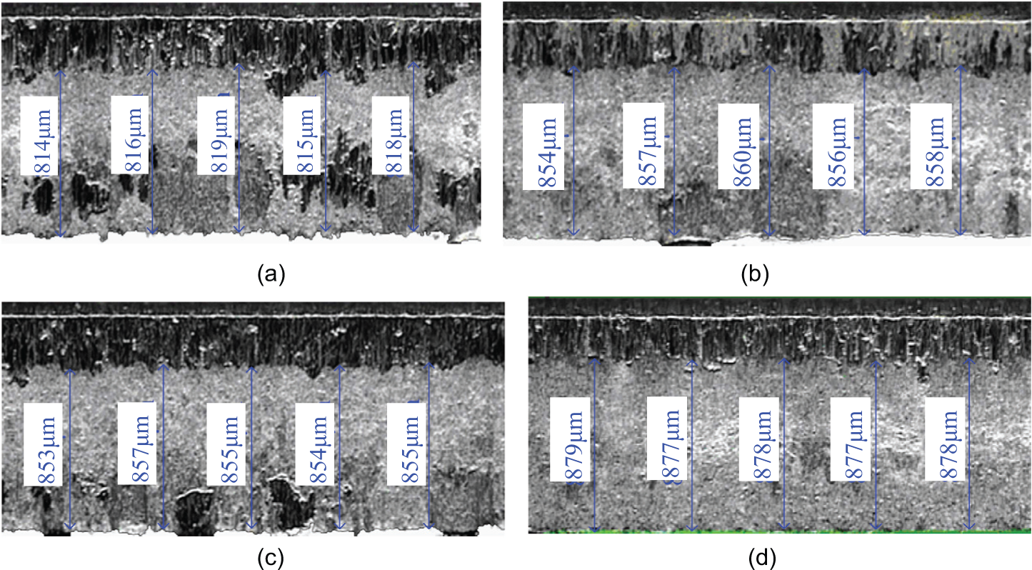
Characteristic features of punched edges on four quadrants: (a) punched by 4Cr13, (b) punched by Caldie, (c) punched by SKD11 and (d) punched by D60/A2.
Figure 13 shows the edge quality effect with clearance 4% and 6% of the tested die materials after 40,000 strokes on the relative rollover depth r/t, relative burnished depth a/t, relative fracture depth f/t and relative burr height b/t (r is the value of rollover depth, a is the value of burnished depth, f is the value of fracture depth, b is the burr height and t is the thickness of sheet metal.)
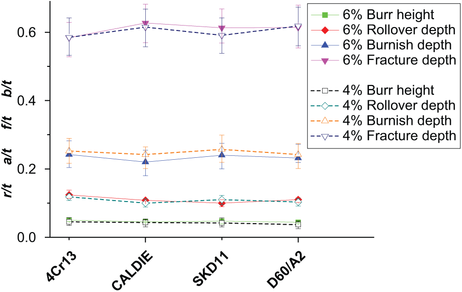
Effect of die materials on the shape of the punched edges.
For each die material, it is shown that the burr height with clearance 6% is higher than the one with clearance 4%, and the total length of burnish and fracture with clearance 6% is shorter than the one with clearance 4%; the reason for it has be explained in forepart in detail. After all, the blanking clearance between punch and die is a significant parameter and has an important effect on blanking force and blanked edge equality including the four characteristic features.
From Figures 12 and 13, it can be concluded that the cross-sectional quality blanked by D60/A2 has the longest total length of fracture and burnish, and the one of 4Cr13 has the least one. Because there are many die wear and chipping happened in the quadrant consisting of 4Cr13, which directly results in the fact that the clearance of 4Cr13 quadrant becomes larger and irregular, and the clearance of D60/A2 is, however, only enlarged a little bit due the least wear of D60/A2.
Conclusion
An experimental and numerical study of punching die materials was implemented by use of a developed X-die setup with four inserts for punch and die, and the following conclusions can be drawn from this study:
An X-die setup for blanking DP780 sheets was developed so that different die materials can be investigated comparatively at the same blanking conditions with varied die clearances.
Experimental results show that the cemented carbide D60 has the best wear resistance performance because of its fine grains and highest strength. Following is Caldie which has the same level as the wear resistance of A2, and both of them have higher wear resistance than SKD11/4Cr13 that had worse uniform particle distribution and lower degree of regularity.
The wear resistance performance of 4Cr13, after 40,000 strokes punching, can reach the level of SKD11 due to the same component product of chromium as SKD11. It can be seen that the carburized 4Cr13 may be used as cold work tool steel like SKD11 to form some sheet metal components.
Under the same experimental conditions, D60 had the best chipping resistance. Inversely, 4Cr13 was the worst one because of its biggest size of carbide.
Footnotes
Acknowledgements
We appreciate the support from Prof. Jiansheng Pan and Mr Qiulong Chen from the School of Material Science and Engineering, who developed the technology for heat treatment and surface carburization of F-M stainless steel.
Declaration of conflicting interests
The authors declare that there is no conflict of interest.
Funding
This work was funded by the University Research Project from Ford Motor Company to compare die materials for forming AHSS sheets.