
Abstract
Ti-6Al-4V titanium alloy and 5A06 aluminum alloy were successfully butt-joined by friction-stir welding method utilizing a special design of butt-joint configuration. The tool-pin was bias placed toward the aluminum butt-side, accompanying with an excess plunge value of tool shoulder into the top surface of aluminum sheet. The as-welded interface characteristics, joining mechanisms and tensile properties of the modified titanium/aluminum dissimilar butt-joint were performed. Experimental results indicated that the defect-free butt-joints with good formation quality were obtainable when the rotation speed of 1200 r/min, the travel speed of 60 mm/min and the pin offset of 0.5 mm were tailored. The stir nugget zone in joints exhibited a composite-like structure of titanium-alloy particles distributed in aluminum-alloy matrix, with an obvious so-called onion-ring morphology. The energy-dispersive X-ray spectroscopy detections showed that no bulky intermetallic compounds were formed at the titanium/aluminum as-welded interface. The maximum tensile strength of the joint was 265 MPa, which generally reached 84.13% of that of the parent 5A06 aluminum alloy.
Keywords
Introduction
Titanium (Ti) and its alloys are widely used in multiple industrials due to their high specific strength, excellent fatigue and corrosion resistance. 1 The low density, good plasticity and outstanding electrical conductivity make aluminum (Al) and its alloys to be the ideal lightweight material. 2 As the target to combine the points of material performance, weight reducing and production cost, which is proposed by the aviation industry, joining the dissimilar alloys of Ti and Al to produce composite structures is strongly motivated. 3
However, both Ti alloys and Al alloys are very active and easy to be oxidized. 4 Moreover, many great differences exist between the two dissimilar alloys, in terms of physical and chemical properties. Ti and Al can be infinitely miscible in liquid. But, Ti has low solubility in solid-state Al grains. Due to the great challenges in the welding or joining of dissimilar Ti and Al, the conventional welding methods hardly meet the requirements of the Ti/Al joint performance for applications.5,6
As an emerging solid-state joining technology invented by The Welding Institute (TWI), UK, in 1991, 7 friction-stir welding (FSW) is a potential candidate for the joining of dissimilar materials due to many technical advantages contributed by its lower processing temperature than the conventional fusion welding.8,9 The most convenient joint configurations for FSW in industry are butt-joint and lap joint. Besides, other types of joint designs, such as T-joints and fillet joints, are also obtainable via FSW for some engineering applications. 10 The good formability and less joint deformation or residual stresses make FSW to be an effective method to solve the conventional welding problems of dissimilar materials, for example, Al and Ti alloys. Up to now, some researchers have conducted some preliminary studies on Ti/Al dissimilar FSW. Ti/Al butt-joints with good formability have been achieved.11–13 Chen and Nakata 12 reported on friction-stir lap welding between Al alloy and pure Ti, obtaining a maximum anti-failure strength of 62% of the Al base material strength. But a lot of intermetallic compounds would be inevitably produced in their research studies. They have not put theoretical research forward about the as-welded Ti/Al interfacial evolutions and joining mechanisms.
Accordingly, in this study, the Ti-6Al-4V Ti alloy and 5A06 Al alloy were used as the substrates to constitute a modified butt-joint configuration for FSW. The welding process parameters were optimized. The effects of pin-offset value on the macro/micro-structure characteristics and dissimilar Ti/Al interface structures, with the L-type modified joint configuration, were further studied. 14 The as-welded Ti/Al interface structural evolution and its joining mechanisms via FSW method were also elucidated.
Experimental details
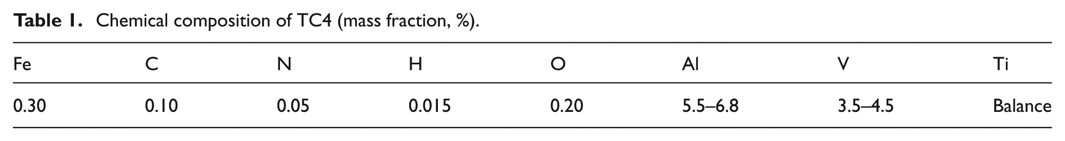
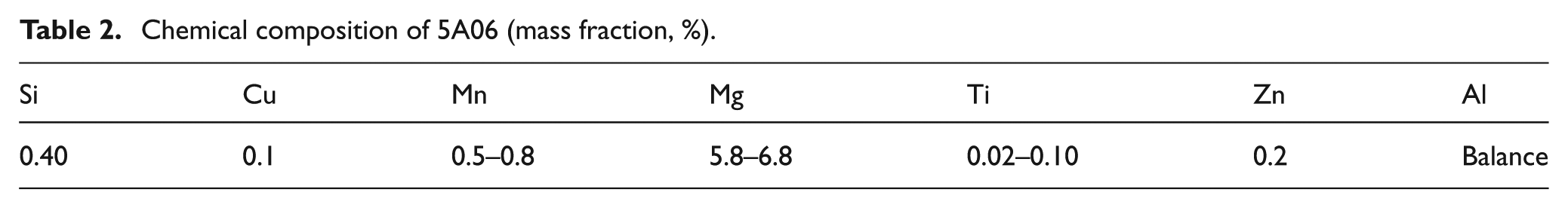
The 2-mm-thick plate of Ti-6Al-4V Ti alloy and 4-mm-thick plate of 5A06 Al alloy were used as parent materials in the experiments. The nominal chemical compositions of the materials are given in Tables 1 and 2. The mechanical tensile strength and elongation of the 5A06 Al alloy are 315 MPa and 16%, respectively. A 2.2-mm-thick plate was partly removed from the top surface of Al-alloy plate by mechanical milling method and then left the cross section of L-type shape. The Ti-alloy plate was ultrasonic cleaned in 10 g/L sodium hydroxide solution at 80 °C for 20 min to remove oil pollution from the surface and then etched in 50% (volume fraction) hydrochloric acid solution to remove oxidation film. The plates were cleaned with acetone and then got dried. The same method was used for surface treatment of the Al-alloy plates.
Chemical composition of TC4 (mass fraction, %).
Chemical composition of 5A06 (mass fraction, %).
During FSW procedure, the Ti-6Al-4V plate was placed over the Al-alloy plate. And they were settled at the advancing side (AS) and the retreating side (RS) of the tool-pin, separately (as shown in Figure 1). In order to prevent the oxidation of Ti-alloy matrix and Ti/Al interface, the experiment was conducted at an atmosphere of 99.9% pure argon as the shielding gas. The butt-joints were welded using an FSW tool made of YG12, WC-12 wt.% Co hard alloy. The tool consisted of a concave shoulder of 15 mm in diameter and a tapered pin of 2.2 mm in length, 6 mm in its root diameter and 4 mm in its top diameter. Contrary to the conventional friction-stir butt-welding, the tool-pin center was bias plunged toward the Al plate side, which was fixed on the RS.15–17 An upsetting value of 0.2 mm in height was asymmetrically added to the Al side. The main welding process parameters are shown as follows: the rotation speed n (r/min), the travel speed v (mm/min) and the stir pin offset T (mm). The weld control mechanism adopted during the experimental study was the fixing of z-axis coordinate position.
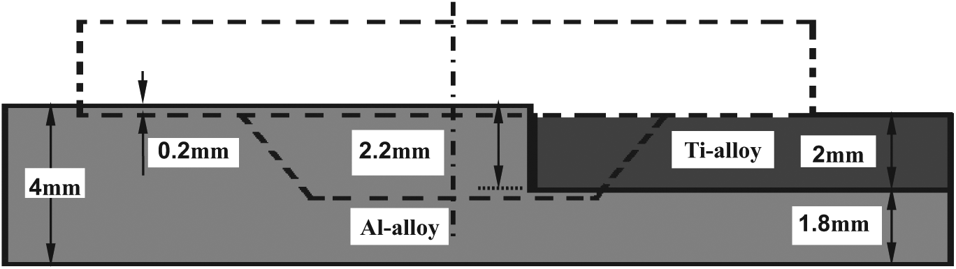
Schematic diagram of the modified FSW butt-joint.
After welding, the joint cross sections were cut perpendicularly to the welding direction for metallographic analyses by the electronic spark linear cutting method. The cross sections of the metallographic specimens were polished with a diamond polishing agent, etched with Keller’s reagent (1 mL hydrochloric acid, 1.5 mL nitric acid, 2.5 mL hydrofluoric acid and 95 mL water) for the 5A06 Al alloy and Kroll reagent (2 mL hydrofluoric acid, 4 mL nitric acid, 94 mL water) for the Ti-6Al-4V Ti alloy. The as-welded microstructures of the specimens were observed by optical microscope (OM), and after that the specimens were cleaned with alcohol and dried. The as-welded Ti/Al interfacial microstructure and chemical component element distribution were analyzed by scanning electron microscope (SEM) equipped with an energy-dispersive X-ray spectroscopy (EDS) system.
The mechanical properties of the joints were measured by tensile tests, which were performed at room temperature and at a tensile speed of 0.5 mm/min by a mechanical tensile testing machine. The average failure loads of the joints were evaluated using three tensile specimens cut from the same joint. 12 And the tensile specimens were surface machined according to a national standard with the specimen width of 12 mm (as shown in Figure 2). The expression for the mechanical tensile strength is
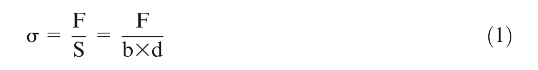
where σ is the mechanical tensile strength (MPa), F is the tensile force (kN), S is the tensile specimen with cross-sectional area (m 2 ), b is the tensile specimen width (m) and d is the thickness of the Ti-alloy plate (m). In this research, the width of each tensile specimen was 12 mm, and the thickness of Ti-alloy plate was 2 mm, and therefore, the cross-sectional area was calculated as

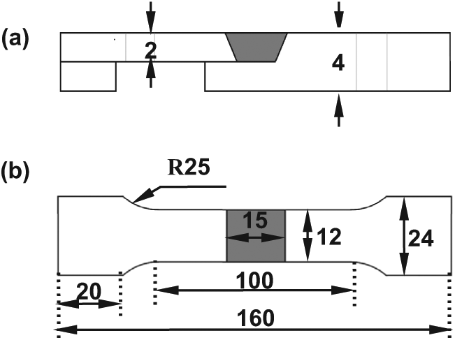
Schematic diagram of the size of the tensile test specimen (mm). Note: the numbers in the figure are size values. The R25 is the direction of the circular arc.
Finally, the fracture surface was analyzed by SEM and EDS.
Results and discussion
Butt-joint configuration design and process optimization
According to the previous reports,11–13 the main problems of Ti/Al friction-stir butt-welding were the pin wear and the inaccurate plunge when the stir tool plunged into the high-strength Ti-alloy side. A large number of Ti/Al intermetallic compounds would be produced at the interface of Ti/Al butt-joint because of the high heat input during the welding process. Bulky intermetallic compounds would have a negative influence on the performance of the butt-joints. 18 Lack of penetration defects would occur when the pin plunge was not enough and the pin would be easily broken when the pin touched the welding back-worktable if the pin plunge value was too large. And the suitable pin plunge could not be easily achieved by an accurate control. With the Ti alloy as the bottom plate, the Al alloy would melt because of its low melting point during the Ti-alloy plasticized deformation, when the stir pin plunged into Ti-alloy plate.12,13 In the case that the bottom plate was set as the Al alloy, the Ti alloy could not be plasticized efficiently due to the lack of the heat input produced by the friction-stir actions when the stir pin plunged into the Al alloy. This would lead to a discontinuous material plastic flow and produce a lot of macro defects, such as voids and grooves.
Based on the joint configuration design with different thickness of butt sheets and an excess pin-offset setup in this research, the stir pin entirely plunged into the softer Al alloy and slightly contacted with the Ti-alloy plate surface. This would reduce pin wear and overheating at the Al-alloy side. This special design concept well balanced the bending resistances between AS and RS during FSW process of Ti/Al dissimilar metals and thus extended the service life of the stir tool.19–21 An upsetting value of 0.2 mm in height was added to Al side in asymmetric, and the tool shoulder was only contacted with the Al alloy but not with the Ti alloy. This would greatly reduce the friction heat between the shoulder and the matrix. Thus, the FSW of Ti/Al dissimilar metals may have three main heat sources, including the friction heat between shoulder and Al alloy, the stir heat between stir pin and alloys (mainly the Al alloy) and the heat released from the plastic deformation of alloys.11–13 Therefore, comparing to the traditional FSW joint configurations, the use of modified butt-joint configuration design with the excess pin offset and different thicknesses of matrixes greatly reduced the heat input during FSW process and the amount of brittle intermetallic compounds. It would efficiently improve the mechanical properties of the welds. Apart from the most convenient joint configuration of butt-weld and lap weld, many other types of joint design, such as T-shaped fillet joints, can also be produced by the FSW technique. 22 In this article, the use of the modified L-type composite butt-joint configuration could effectively prevent the occurrence of defects such as the lack of penetration at the butt-root position when the stir pin slightly plunged into the lower part of the Al alloy. All these methods contributed to the successful bonding of Ti/Al dissimilar metals.
In order to obtain a high-quality joint, FSW process parameters were optimized in advance because the main FSW parameters greatly affected weld defect occurrence, plastic deformation heat generation, thermo-mechanical properties and local material characteristics in the welds.23–25 According to previous FSW process optimization experimental results, the optimal welding parameters were obtained as the following experimental conditions: the rotation speed n of 1200 r/min, the travel speed v of 60 mm/min and the pin offset T of 0.5 mm. Under these welding parameters, the welds with good formability and high tensile strength could be achieved.
Butt-joint macrostructure
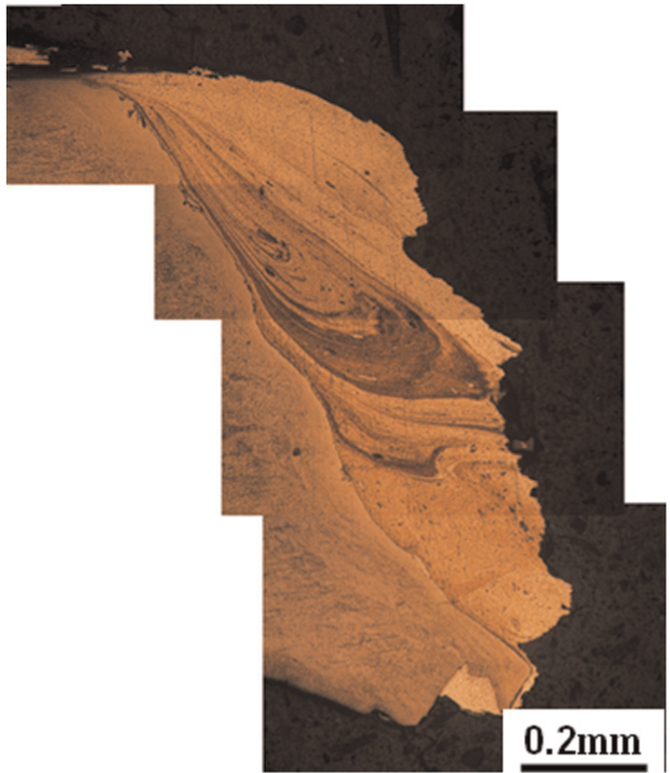
Figure 3 shows the macrograph of as-welded cross section of the dissimilar friction-stir welds of Ti-6Al-4V alloy and 5A06 alloy. The pin was shifted toward the softer Al alloy, so the stir nugget zone (SNZ) mainly exhibited at the Al side of the joint. It was revealed at the SNZ that a mixture of fine recrystallized grains of Al alloy was produced with Ti-matrix particles, which were pushed away from the Ti plate surface by the stirring action of the stir pin. Therefore, the SNZ had a composite-like structure of Al-alloy matrix reinforced by Ti particles. 11 Most parts of SNZ presented a kind of vortex flow structure (Vortex flow-I and Vortex flow-II), which was the typical onion-ring morphology. Besides, a turbulent flow structure and some Ti particles in a large size could be observed within the SNZ. At the lower part of SNZ, the location at the stir pin root, obvious Hook structure was found, which usually generated in the friction-stir lap welds.12,13Figure 3(b) shows a vortex flow structure indicated by the white arrows. A lot of small Ti-alloy particles dispersed uniformly along the direction of the vortex flow structure. In Figure 3(c), a gray zone was produced around the Hook structure, which was a composite-like structure.
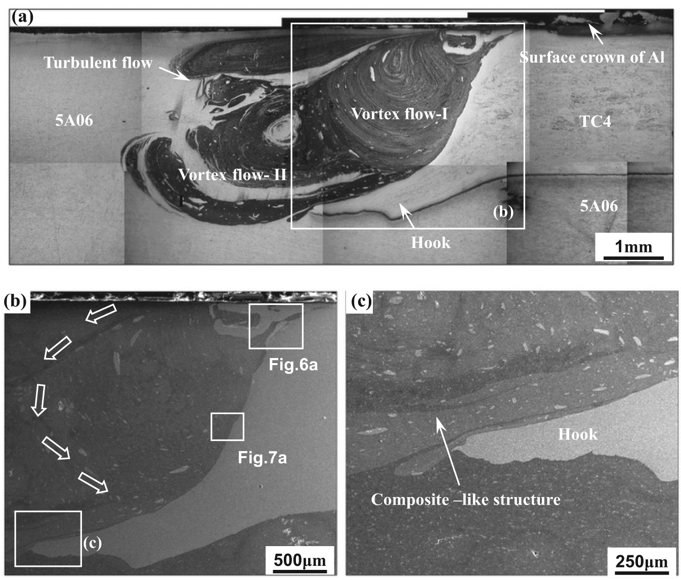
(a) Macrograph of Ti/Al FSW joint taken perpendicular to welding direction, (b) micrograph of Ti/Al joint shown in Figure 3(a) and (c) micrograph of Ti/Al joint shown in Figure 3(b).
As we all know, when the stir pin plunged mainly into the softer Al-alloy side, the Al matrix experienced severely plastic deformation heat produced during the welding process. The materials would flow around the stirring pin and form the typical onion-ring structure in the SNZ. However, the Ti alloy also experienced mechanical–thermal cycles in the SNZ due to the stirring action. The Ti-alloy band at as-welded interface was elongated and embedded into the lower part of the Al-alloy side, and then the Hook structure was produced. No crack was observed around the Hook structure in Figure 3(c). The stir pin touched the faying face of the Ti alloy due to the configuration design of pin offset. Thus, a lot of Ti particles were pushed away from the Ti-alloy matrix and dispersed in the SNZ as reinforce particles. Besides, the Ti alloy and Al alloy were fully mixed at the root of the stir pin, and then a composite-like structure was produced along the Hook structure, which would contribute to a higher bonding strength at the as-welded interface.
The main process parameters for optimization during FSW procedures included tool travel speed (v, mm/min), tool rotation speed (n, r/min) and bias-plunge length into Ti butt-side of the pin top end, which was defined as the pin offset (T, mm). In order to investigate the characteristics of as-welded Ti/Al butt interfaces under the different process conditions, the values of n and T were changed on the condition of invariable v value, 60 mm/min. The groups of the FSW process experimental works after parameter alteration were listed in Table 3. Besides, the tool shoulder plunge depth downward the top surface of Al-alloy sheet (d, mm) was unified tailored as 0.2 mm (as indicated in Figure 1). Besides, the tool tilt angle (α, °) was unified as 0° in the present experiments.
FSW process parameters with the corresponding process conditions and the joint macroscopic formability results.
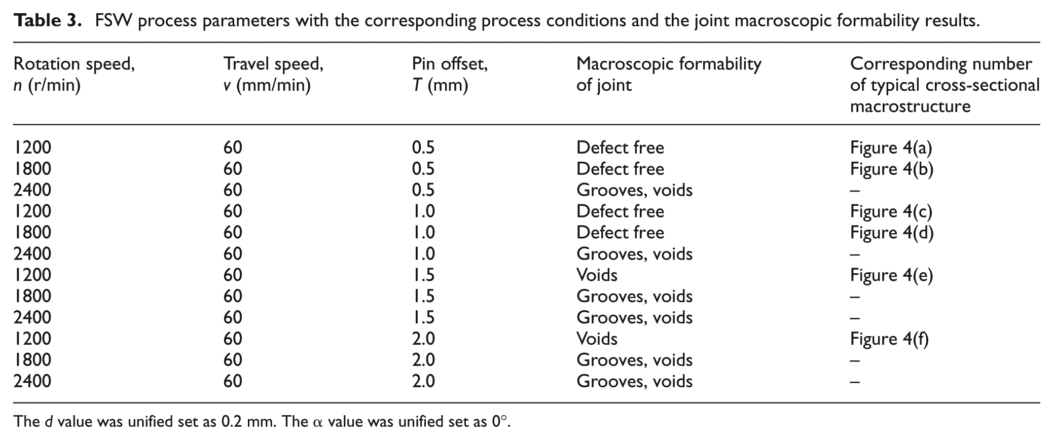
The d value was unified set as 0.2 mm. The α value was unified set as 0°.
The tailored FSW process conditions corresponding to the butt-joints shown in Figure 4 are listed in Table 3. Figure 4(a) shows the typical macrostructure of the butt-joint, which has been discussed above (process condition: n = 1200 r/min, v = 60 mm/min, T = 0.5 mm). When the rotation speed increased to 1800 r/min, the three partial zones marked as “Vortex flow-I,”“Vortex flow-II” and “Turbulent flow” had nearly the same positions as those in the SNZ produced in Figure 4(a). But within the “Vortex flow-II” region, several large-sized Ti fragments remained (Figure 4(b)). On the macroscopic scale, the Al-matrix material flow patterns in Figure 4(c) presented different characteristics in SNZ under the process condition with T value of 1.0 mm from that of 0.5 mm (Figure 4(a) and (b)). The size of “Vortex flow-I” zone decreased, while that of “Turbulent flow” zone was obviously enlarged to occupy a major position in the middle part of SNZ (Figure 4(c)). And the large-sized Ti-6Al-4V fragments produced in the SNZ were relatively far away from the butt-welded interface. Figure 4(d) shows the cross-sectional macrostructure when the value of n increased to 1800 r/min on the condition of invariable v value (60 mm/min) and T value (1.0 mm). The Al-matrix turbulent flow pattern in SNZ was more obvious on the macroscopic scale. The deformation degree of Ti-6Al-4V Hook structure was significantly greater comparing with that of other joints produced using lower T value or lower n value. As indicated in Figure 4(e), since the pin-offset value toward the Ti-alloy butt-side increased gradually, more large-sized Ti fragments remained in SNZ. Some voids at the interface between the Ti fragments and their adjacent Al-matrix material appeared. The macroscopic appearance of Al-matrix turbulent flow patterns occupied the middle part of SNZ. As shown in Figure 4(f), when the value of pin offset toward Ti-alloy butt-side was 2.0 mm, several evident voids appeared in SNZ with large-sized Ti-alloy fragments. The macroscopic defects in the joint certainly did harm to the mechanical properties due to the severe lack of material.
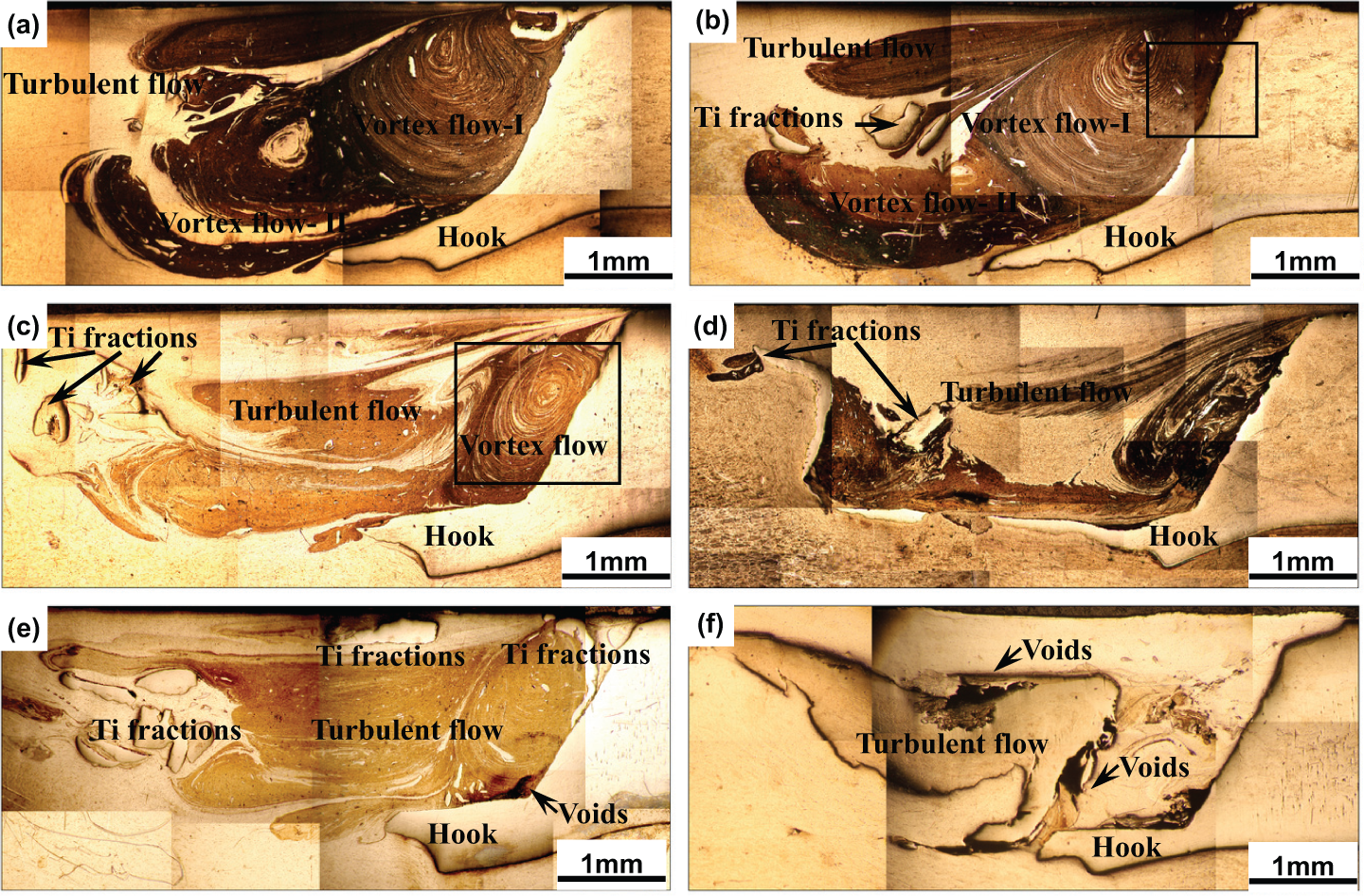
Macrographs of Ti/Al FSW butt-joint under different process conditions: (a) n = 1200 r/min, v = 60 mm/min, t = 0.5 mm; (b) n = 1800 r/min, v = 60 mm/min, t = 0.5 mm; (c) n = 1200 r/min, v = 60 mm/min, t = 1.0 mm; (d) n = 1800 r/min, v = 60 mm/min, t = 1.0 mm; (e) n = 1200 r/min, v = 60 mm/min, t = 1.5 mm and (f) n = 1200 r/min, v = 60 mm/min, t = 2.0 mm.
Butt-joint mechanical properties
The mechanical tensile test results of the modified butt-joints are shown in Figure 5. Five groups of samples under different process conditions listed in Table 3 were tested. The results displayed that the tensile strength and elongation of all joints were lower than those of the parent 5A06 Al alloy. All the samples of the first group under larger loads fractured in the SNZ. The maximum mean tensile strength and elongation of the butt-joints, 265 MPa and 2.25%, respectively, occurred under the condition of 1200 r/min rotation speed and 0.5 mm pin offset. The joint tensile strength reached 84.13% of that of parent 5A06 Al alloy.
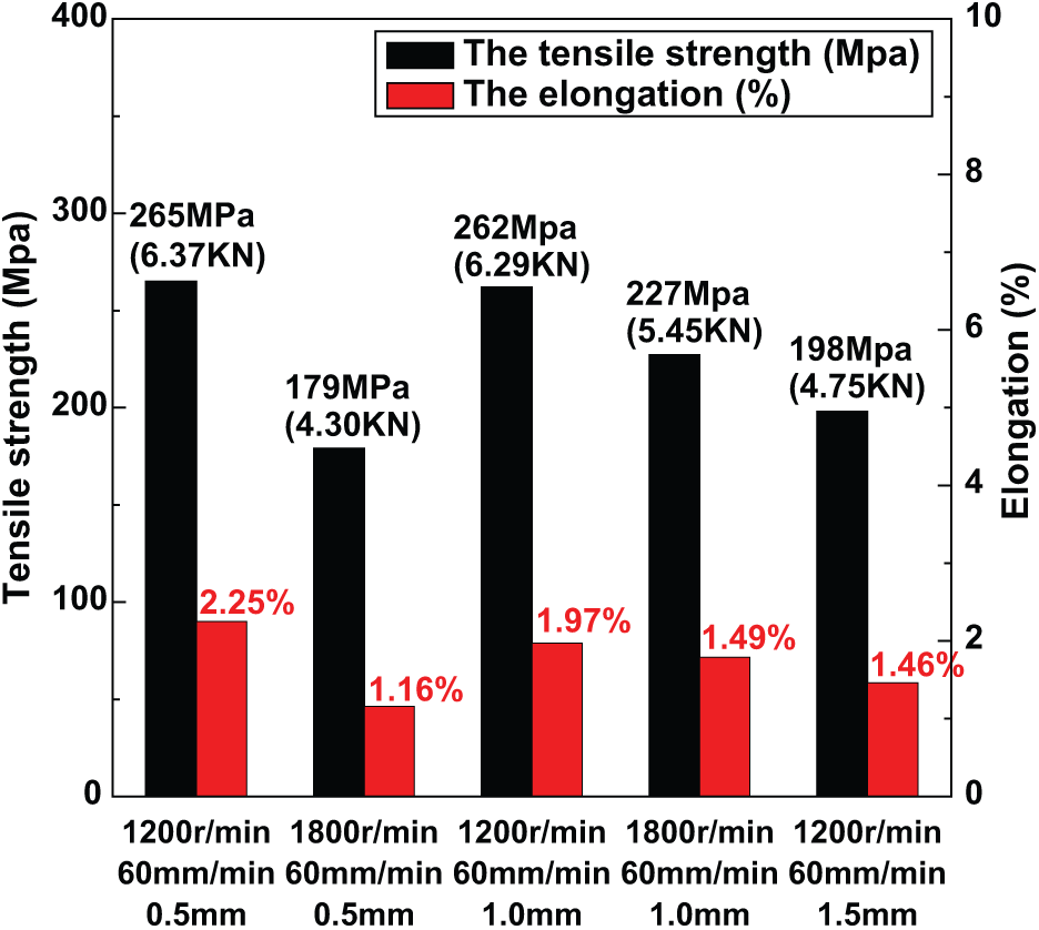
Tensile strength and elongation of Ti/Al butt-joints.
When the rotation speed or the pin-offset value was too low, the two dissimilar alloys, especially the Ti alloy, which has a high melting point, could not be well plasticized or mixed by the low heat input during the FSW process. This would lead to discontinuous flow of plastic or softened material and produce some defects, such as voids and grooves, and then the tensile strength and elongation of the butt-joints would decrease. 8 As the rotation speed or the pin-offset value increased, the heat input increased greatly during the welding process and the alloys, which were better plasticized and mixed. It resulted in forming the continuous plastic flow and efficient bonding at the interface. When the rotation speed reached 1200 r/min and the pin-offset value reached 0.5 mm, the maximum average tensile strength and elongation of the butt-joints were achieved. When the rotation speed or pin-offset value was proceedingly increased, the two dissimilar alloys would be overheated due to the too much heat input provided by the friction-stir action of the stir pin. The Ti/Al intermetallic compounds would be produced and reduced the mechanical properties of the butt-joints.
Butt-joint interface characteristics and interface joining mechanism
A SEM micrograph image of the upper part of the as-welded interface (the region in Figure 3(b)) is shown in Figure 6. The interface of Ti/Al friction-stir butt-joint exhibits a lamellar structure. One material clutched into the other demonstrates intimate contact and presents a macroscopic characteristic of mechanical bonding. 13 Besides, an intermetallic compound layer could be observed at the interface indicated by point A. The EDS result of point A in the reaction layer is shown in Figure 6(b). The main elements of point A are Ti and Al, and the atom radii of the elements are 77.81% and 22.19%, respectively.
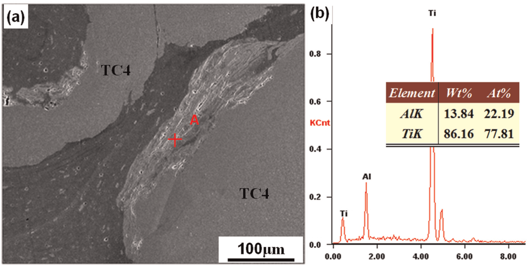
Micrograph of Ti/Al joint shown in Figure 3(b): (a) SEM image and (b) EDS result of point A.
During the FSW process, the upper part of the matrixes experienced mechanical and thermal histories because of the friction-stir action and the upsetting force, and more heat was produced under the tool shoulder. Too much heat input resulted in the occurrence of the intermetallic compound layer.26,27 The EDS result of point A suggested that the Ti alloy and Al alloy experienced severely plastic deformation, elemental diffusions and reactions between Ti and Al, which inevitably occurred at the interface. The intermetallic compound layer might have a negative influence on the Ti/Al dissimilar butt-joint. However, the reaction layer was limited and discontinuous due to the application of the pin-offset design. So the bad influence could be reduced in a large degree. And the bonding strength of butt-joints could be greatly improved.
Figure 7 shows the SEM of the region marked in Figure 3(b). A composite-like structure of Al alloy reinforced by Ti particles could be easily observed in Figure 7(a). According to the EDS profiles of Ti and Al elements of Zone B, as shown in Figure 7(b), it was deduced that the thickness of the Ti/Al diffusion interlayer at the butt-welded interface was about 2.5 µm. Some weak curve fluctuations could also be found within the Ti/Al element concentration profiles in Figure 7(b). 28
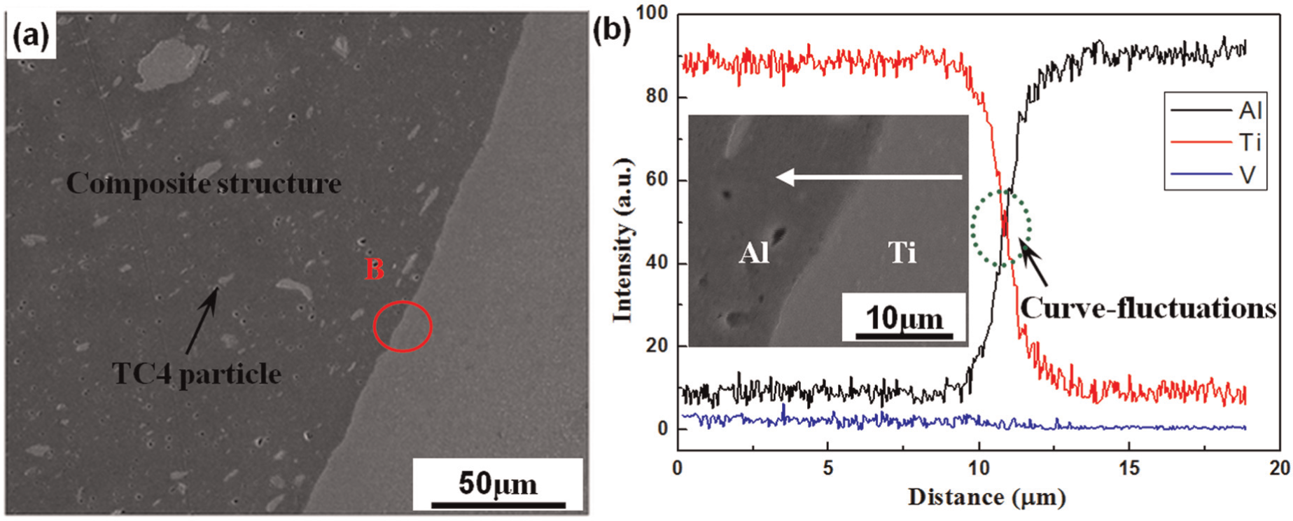
Micrograph of Ti/Al joint shown in Figure 3(b): (a) SEM image and (b) EDS result of Zone B.
The two dissimilar alloys were completely mixed to produce the composite-like structure. Comparing with the severe deformation at the upper part of the interface, the matrixes at the lower part of the interface only experienced the stirring action by the stir pin without the upsetting force. So the heat input was lower than that of point A; only element diffusions and solid solutions occurred at this zone. The monotonous element distribution of Ti and Al also proved that no intermetallic compound was produced at the interface. Since no intermetallic compound layer could be found at this zone, it generally proved that a Ti/Al diffusion-typed interface was generated to certify a typical characteristic of metallurgical bonding. However, due to the lack of diffusion duration time during the FSW process, the Ti/Al diffusion interlayer was not too thick. 11
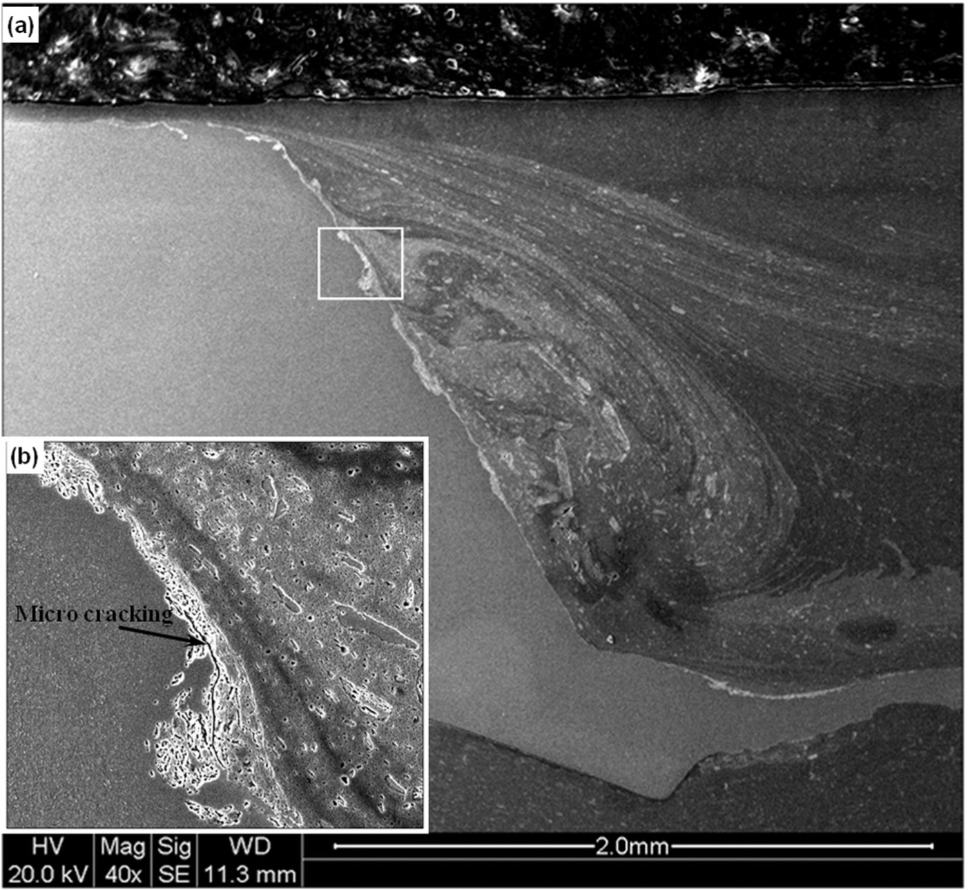
Figure 8(a) gives the macrostructure of the partial region marked in Figure 4(b); obvious onion ring could be found. And some continuous bulky intermetallic compound interlayer structures were produced, as shown as the dark layer at the butt interface in Figure 8(a). Figure 8(b) shows the typical microstructure of the as-welded Ti/Al butt interface at the top part, as marked in Figure 8(a). Under this process condition (n = 1800 r/min, v = 60 mm/min, t = 0.5 mm), an intermetallic compound interlayer with about 10 µm in thick constituted an Ti/Al reaction-typed interface zone, which had a different structure by comparison with the Ti/Al diffusion-typed interface, as shown in Figure 7(a). It should be the result of elevated n value of the stir pin during the FSW procedure to form the new Ti/Al butt interface with metallurgical bonding. The EDS line scan result of Ti/Al butt interface in Figure 8(b) is shown as Figure 8(c). According to the curve fluctuations in the main element concentration profiles, two adjacent interlayer structures with different Ti/Al phases were seemed to be identified as Layer 1 mainly of Ti3Al and Layer 2 mainly of Ti/Al. By the observation on the top part within the overall Ti/Al butt interface structure, the main Ti/Al phase of the intermetallic compound interlayer was Ti3Al, which was formed due to the more heat generation by the pin with the increased rotation speed.
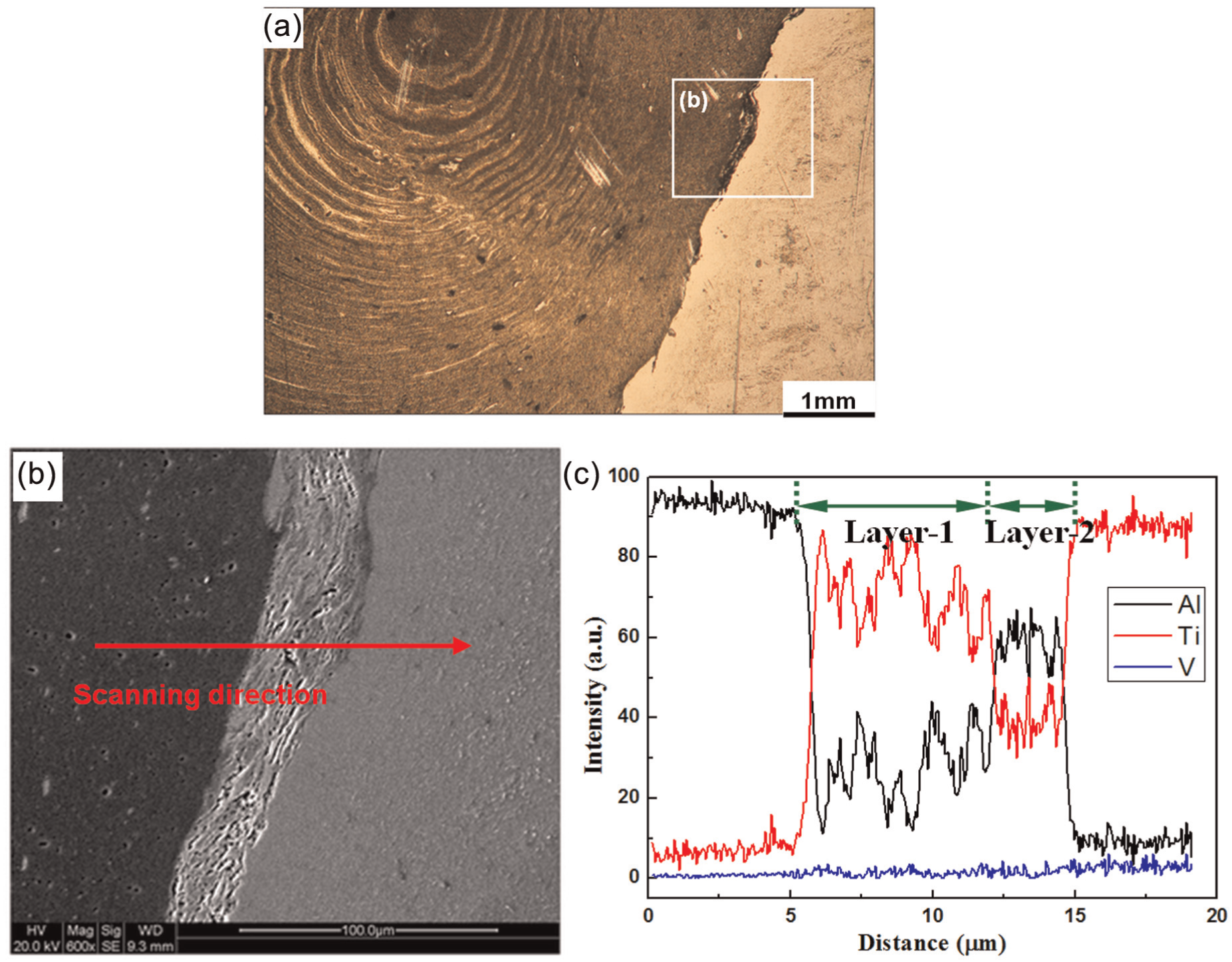
Macrostructure/microstructure examinations of the localized region marked in Figure 4(b). (a) Joint cross-sectional macrostructure by OM, (b) SEM image of the localized region marked in (a) and (c) the main element profiles by EDS line scan detection in (b).
Figure 9 shows the SNZ consisting of as-deformed Al alloy and numerous dispersed Ti-alloy particles embedded in the Al-matrix material, which could be regarded as a particle reinforcement composite structure. No microcracks were found at the butt interface. The main element concentration profiles by EDS line scan of Region A along the direction of the marked line are shown in Figure 9. No significant oxygen element composition was found, and the effective thickness of the Ti/Al diffusion-typed interlayer at the butt interface was about 2 µm.
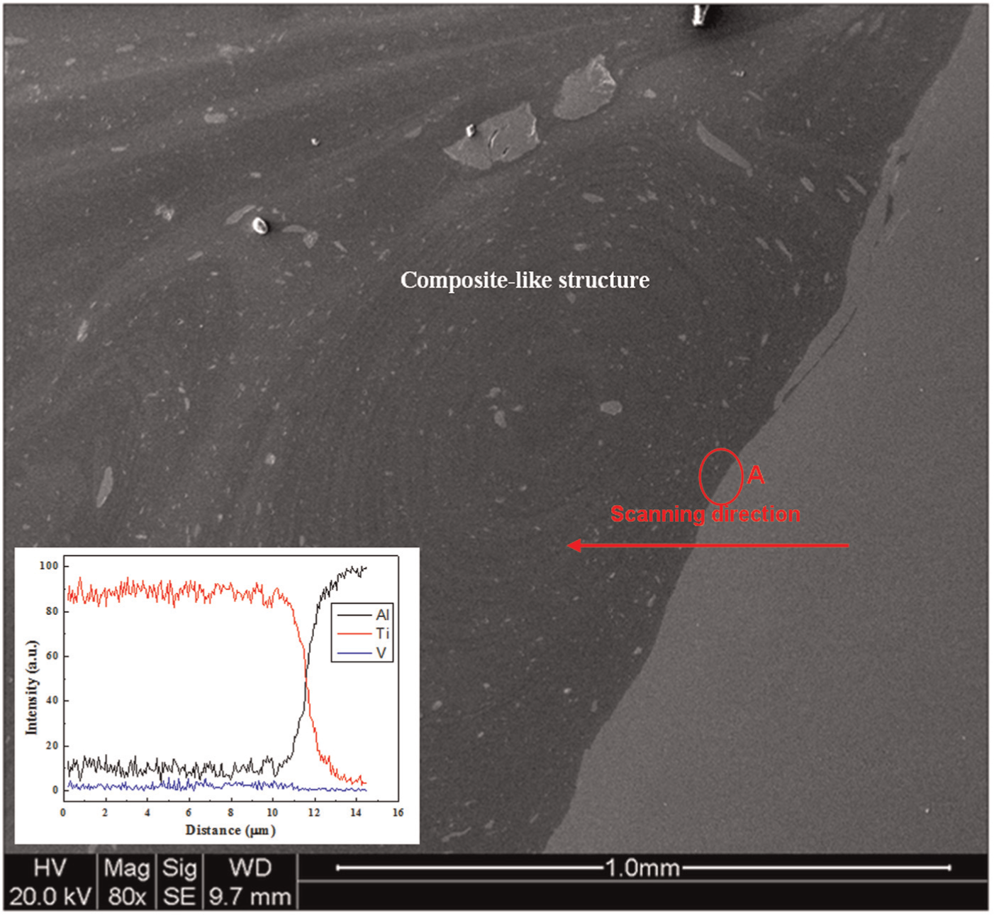
SEM image of the localized region marked in Figure 4(c) and the main element profiles by EDS line scan detection of Region A.
Figure 10(a) gives the SEM image of the local regions marked in Figure 4(d). The vortex flow morphologies of Al-matrix material embedded with dispersed Ti-alloy particles were fabricated next to the butt-welded interface. As shown in Figure 10(b), several discrete bulky intermetallic compounds were produced and distributed along the Ti/Al butt interface. Although the generation of Ti/Al intermetallic compound proved that the metallurgical bonding was obtained, some micro cracking was also found, as indicated in Figure 10(b), maybe due to the significant mismatch of thermal expansion coefficient of intermetallic compound and matrix materials.
(a) SEM image of the localized region marked in Figure 4(d). (b) SEM image of the localized region marked in (a).
After the tensile test, the fractured samples of the butt-joints were analyzed. The butt-joint fractured in the SNZ at the Al-alloy side under the largest failure load, and the lateral micrograph of fracture surface at the Ti side is shown in Figure 11. The material at the left side was the Ti-alloy matrix, and the right one was a structure rich in Al attached to the Ti-alloy matrix at the fracture surface. Vortex flow structure and composite structure could be easily observed in Figure 11.
Lateral micrograph of fracture surface on Ti/Al butt-joint.
The Ti and Al alloys were fully mixed due to the friction-stir action, and a composite-like structure was produced at this zone. 11 Mutual element diffusions and solid solutions improved the bonding strength at the interface. During the FSW process, finely recrystallized grains of Al alloy produced in the SNZ contributed to the strength of this zone. 11 However, the SNZ at the Al-alloy side in this research was a composite-like structure reinforced by Ti particles pushed away from the Ti plate surface. These Ti particles were not uniform; particles in small size did really improve the strength of SNZ, but the large ones reduced the ductility in some degree and turned to be the crack sources during the tensile testing. The butt-joint fractured in the SNZ within the Al-alloy side. It implied that the dissimilar butt-joints had a good interface bonding. The result of the tensile test also proved that the bonding strength at the interface was higher than that of SNZ. The SNZ mainly occurred at the Al matrix, so the macrograph of the fracture surface is an organization rich in Al attached to the Ti-alloy matrix. According to the tensile test, the modified Ti/Al butt-joint with high strength could be easily achieved using FSW method.
Observing the fracture surface of the tensile test specimens, a large amount of dimples could be found at the lower part of the fracture surface in Figure 12(a). However, at the upper part of the fracture surface, smooth surface could be observed, which was cleavage surface. The EDS analysis results of Zones 1 and 2 are shown in Figure 12(b). The main elements of Zone 1 are Al and Ti, and the atom fractions of the elements are 90.01% and 9.99%, respectively. Zone 2 has the same element composition as Zone 1, and the atom fractions of Al and Ti are 98.75% and 1.25%, respectively.
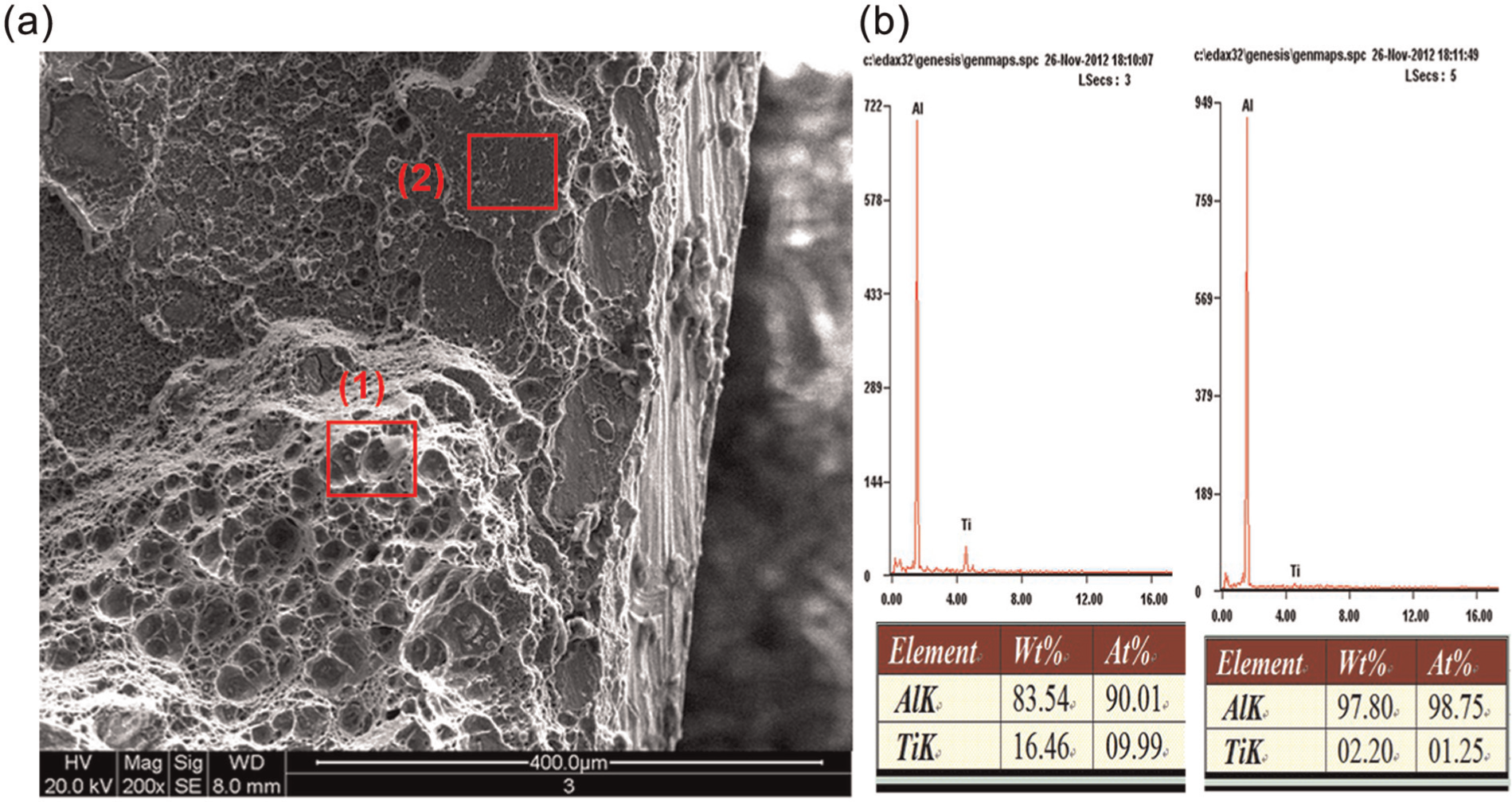
Micrograph of fracture surface on Ti/Al butt-joint at the titanium side: (a) SEM image and (b) EDS results.
The dimples shown at Zone 1 reveal that the main fracture mode is ductile fracture, which suggests that metallurgical bonding was achieved. The bonding strength may be very high at this zone in terms of the high tensile strength. However, the cleavage surface at Zone 2 demonstrates that brittle fracture may occur at this zone. The joining mechanism should be mechanical bonding and the bonding strength may be lower than Zone 1 as usual. 29 The fracture modes and element distribution suggest that the Ti alloy and Al alloy experienced severe mechanical and thermal cycles due to the friction-stir action, forming organizations of mechanical bonding shown in Figure 6(a). At the same time, element diffusions and solid solutions occurred at the interface, and then a diffusion-typed interlayer of metallurgical bonding was formed, as shown in Figure 7(a). So a combination of mechanical bonding and metallurgical bonding was achieved at the interface on Ti/Al butt-joint, and the bonding strength was greatly improved taking advantages of the modified composite butt-joint. 30
Conclusion
In this research, Ti-6Al-4V Ti alloy and 5A06 Al alloy were successfully butt-joined by FSW using a special design of modified butt-joint configuration. The following conclusions are proposed according to the presented results:
At the rotation speed of 1200 r/min, travel speed of 60 mm/min and pin offset of 0.5 mm, the modified friction-stir butt-welds with good formability and high tensile strength were obtainable.
Based on a special design of joint configuration with an pin offset toward the Al side and the different thickness of butt-sides, the less heat input could greatly reduce the amount of brittle intermetallic compounds and efficiently improve the mechanical properties of the butt-joints.
A diffusion-typed interlayer of about 2.5 mm thickness exhibited at the interface. A combination of mechanical and/or metallurgical bonding was achieved at the interface of Ti/Al butt-joints.
The maximum tensile strength of the joints was 265 MPa, reaching 84.13% of that of the parent 5A06 Al alloy.
Footnotes
Declaration of conflicting interests
The authors declare that there is no conflict of interest.
Funding
This study was supported by Funding for Outstanding Doctoral Dissertation in NUAA (BCXJ12-09) and the Fundamental Research Funds for the Central Universities in P.R. China.