
Abstract
Fixturing strategies during the different stages of manufacturing of a part strongly affect the final geometrical outcome on both part level and assembly level. Different manufacturing setups, processes and operations allow for, and put requirements on, the fixturing strategy. In this article, different fixturing strategies during cutting of stamped sheet metal parts are discussed and evaluated with respect to minimized variation in critical features. The strategies are discussed from a theoretical point of view. Geometrical decoupling philosophies are used to minimize the number of variation sources during cutting. The strategies are also illustrated using an industrial case study consisting of laser cutting of a stamped sheet metal part. Some general guidelines, based on the results, for fixturing during sequences of operations are formulated. In this article, fixturing during laser cutting followed by fixturing during assembly are in focus, but the strategies should be generalizable to other sequences of manufacturing operations as well.
Introduction
Geometry assurance is a term used to gather a lot of activities aimed at securing the geometrical quality of the final product. Geometrical variation comes from variation in shape and size of single parts. Variation is also added during the assembly process. To avoid the negative effects from the geometrical variation, it is important to find a robust design concept, that is, a concept as insensitive to variation as possible. The main key to making a physical assembly geometrically robust is to find robust locating schemes. The locating schemes fixate parts in space during manufacturing and joining operations and control how variation propagates in the assembly.
The manufacturing of a complex product, such as a car or another type of vehicle, contains a lot of different manufacturing and assembly steps. In order to achieve products that fulfill functional and esthetical requirements, it is important to reduce the effects of geometrical variation. There are three main factors affecting the level of final geometrical variation of an assembled product: the robustness of the design concept, the part variation and the assembly process variation. 1 In this article, the focus is on minimizing part variation.
A part is usually manufactured during a sequence of operations, such as stamping, laser cutting and other types of machining processes. By paying attention to the choice of locating schemes during the different operations, the geometrical variation in the finished part can be reduced. Kaya 2 and Vishnupriyan et al., 3 use genetic algorithms to optimize the locating schemes during machining. Rong and Bai 4 analyze machining accuracy for computer-aided fixture design. Fan and Kumar 5 apply robust design principles to fixture locating layouts for machining workpieces. ElMaraghy et al. 6 propose a method to compensate for machining errors and improve the geometrical quality of machined parts.
In this article, the proposed method will be applied to laser cutting. An overview of cutting technologies is given by Byrne et al. 7 and Rivin et al. 8
During material removing processes, the repeatability of fixtures is an important aspect when studying geometrical quality. Payne and Cariapa 9 investigate the repeatability of machining fixtures by using a measure to quantify the variability contributed by the fixture in a number of inspection points on a part. Wärmefjord et al. 10 describe a method for transforming the variations in inspection data into variations in the contacts between workpiece and locators, making it possible to include the effect in variation simulations.
Scope of this article
Methods to optimize the locating scheme during machining with respect to minimized variation or deviation from nominal have been treated by a number of authors. The connection to the locating scheme used in the following step, where the part is assembled to other parts, is, however, missing.
The focus of this article is therefore on fixturing during part manufacturing operations and assembly. Strategies for finding robust locating schemes for series of different manufacturing steps, such as stamping and laser cutting of a part, are investigated and some general guidelines are formulated.
In section “Geometrical couplings,” an overview of geometrical couplings and axiomatic design is given. In section “Manufacturing of a sheet metal part,” the different manufacturing steps with corresponding locating schemes for a sheet metal part are described. In section “Evaluation of fixturing strategies during laser cutting,” fixturing strategies for the different manufacturing steps are discussed and evaluated using the principles from axiomatic design theory (described in section “Geometrical couplings”). This leads to some general guidelines for fixturing during laser cutting. Those strategies are applied to a case study in section “Case study.” Discussion will be found in section “Discussion,” and finally, conclusions are addressed in section “Conclusion.”
Geometrical couplings
According to axiomatic design, 11 a good, uncoupled, design is a design where each output is controlled by one and only one input. For physical assembled products, the fixturing strategies, that is, the chosen data and locators, control the geometry and the way variation propagates and affects overall product key characteristics.
For rigid parts, the locating scheme is often described by six discrete points. 12 Those lock the 6 degrees of freedom for a part. For non-rigid parts, additional supports/clamps are often used to handle gravity and other forces due to joining and contacts between parts. 13 Figure 1 shows the concept of locating schemes.
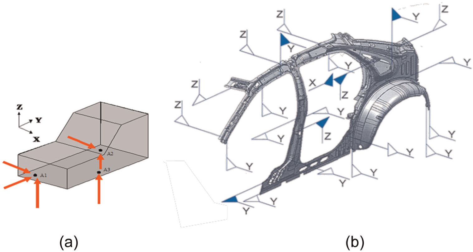
(a) Rigid and (b) non-rigid locating scheme.
In reality, the theoretical locating points are represented by locating features (locators) such as holes, slots, pins and planes. A locating feature can then realize more than one locating point. A hole with its plane controls three directions, a slot controls two directions and a small plane controls only one direction. The locating scheme does also affect the robustness of a part, that is, the ability to suppress the impact of variation in the locating points. 1 A deeper discussion on different locating schemes can be found in Söderberg et al. 12
In Söderberg and Lindkvist, 14 the concept of axiomatic design was applied to assembly robustness evaluation by using the locating scheme (Li) for each part as inputs and the position (Posi) of each part as output (see Figure 2).
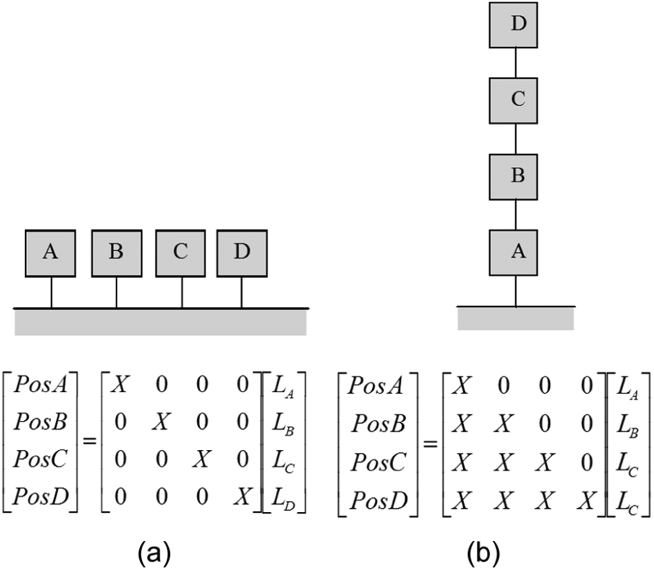
(a) Uncoupled and (b) decoupled assembly.
In the uncoupled assembly (Figure 2(a)), the position of each part is controlled by its own location scheme alone. A decoupled design (Figure 2(b)), characterized by a triangular design matrix, means that unwanted dependencies exist but can be handled by adjusting the inputs in a certain order. To secure the position of Part D, which is dependent on all other parts, one should start by optimizing the locating scheme for Part A, then B, then C and finally D. In Edholm et al., 15 these theories have been developed further to handle decoupling in multistage assembly lines.
The same positioning philosophy as for parts within an assembly can also be applied to individual geometrical features within a part. Figure 3 shows two ways of controlling the position of a number of holes.
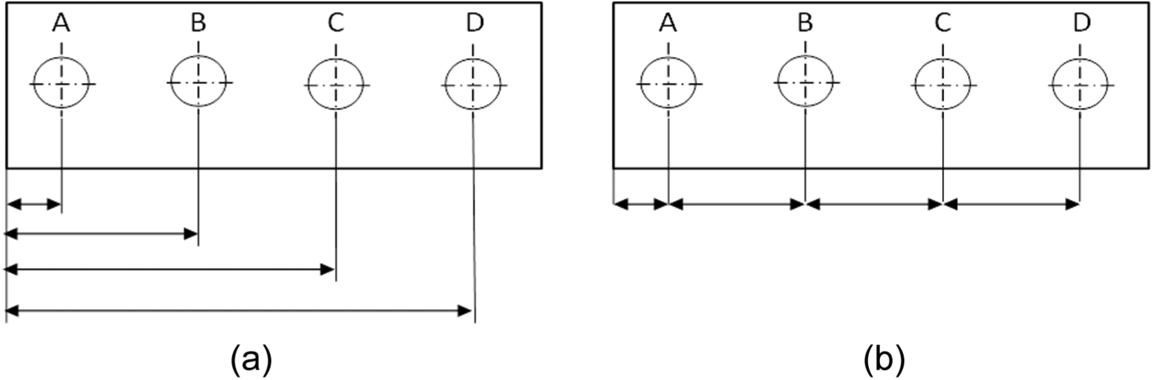
(a) Uncoupled and (b) decoupled positioning of features.
Figure 3(a) shows an uncoupled way to position holes on a part. In this case, the position of each hole is referring to the same data, the left side. This would correspond to a diagonal, uncoupled, design matrix where every feature can be controlled independent of each other. In Figure 3(b), the position of each hole depends on the position of the others in the same way as the decoupled assembly in Figure 2(b).
Making design and manufacturing solutions as uncoupled as possible, that is, reducing the number of contributing variation sources, is critical for securing robustness and high quality. In Edholm et al., 15 those ideas were applied to an assembly line. In this article, these philosophies will be applied to the task of finding the optimal manufacturing strategy for a sheet metal part with different forming, trimming and fixturing sequence options.
Manufacturing of a sheet metal part
In this section, the manufacturing steps of a stamped sheet metal part are described. The description is given from the perspective of geometrical quality. In the following, three different locating schemes (sets of physical locators) will be used:
The laser cutting locators—the locating scheme used for laser cutting;
The inspection locators—the locating scheme used for inspection;
The customer locators—the locating scheme used by the customer during final assembly.
The customer locators are usually also used during inspection of the part.
A sheet metal part is usually manufactured in a sequence of operations. The most interesting steps from a geometrical variation point of view are as follows:
A blank is formed to its desired shape by stamping in a metal press. Cold or warm stamping can be used. The die is constructed in order to compensate as far as possible for spring back after stamping. Locating holes and slots can be punched during this operation.
Laser cutting or other machining operations are applied to remove extra material used to position the part during stamping. During laser cutting, the part is positioned using the so-called laser locators. The final hole and slot used in step 3 (customer locators) can be cut.
The final part is inspected and delivered to the customer. The component will be part of a subassembly, and during joining, it will be positioned using customer locators. The part is also evaluated in an inspection fixture using the customer locators.
An illustration of these steps is shown in Figure 4.
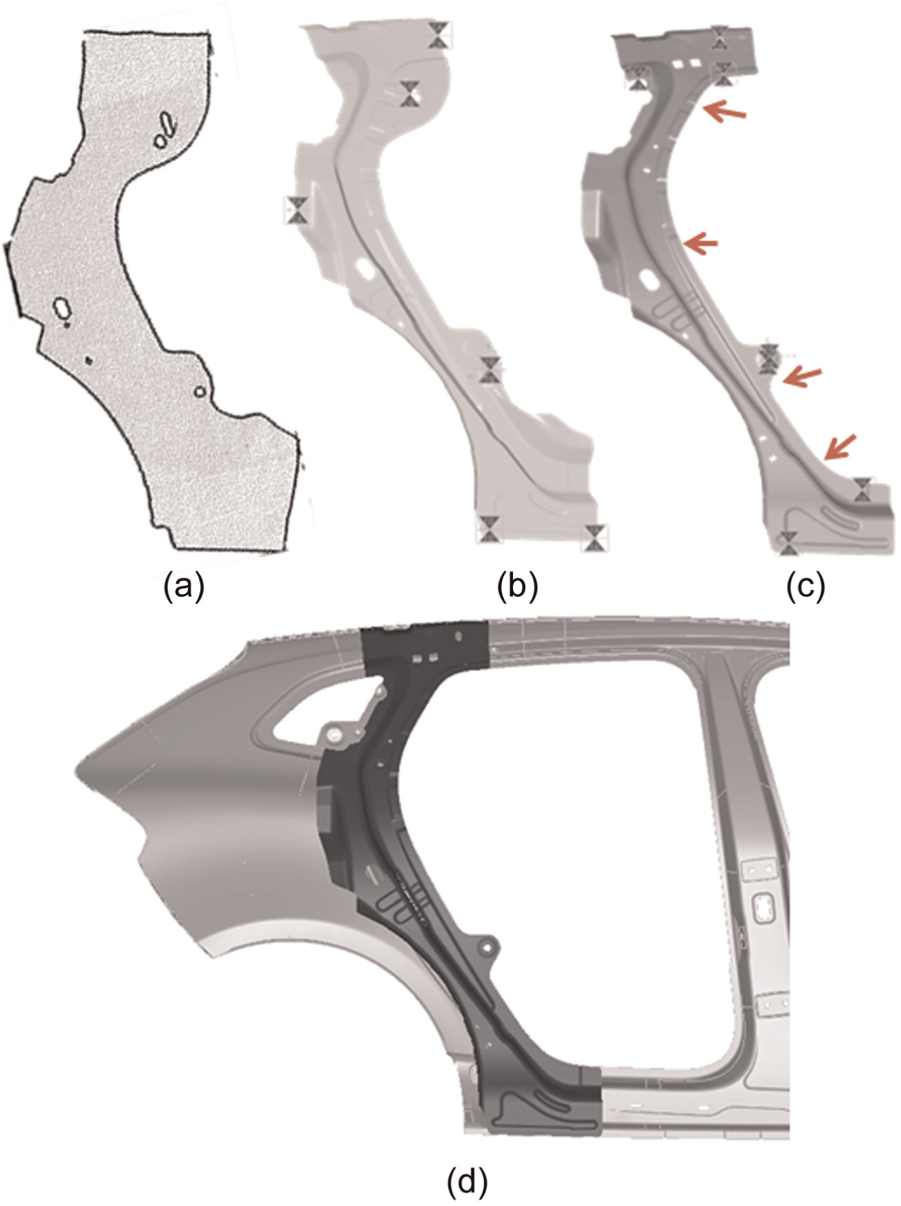
Illustration of (a) a blank before stamping; (b) a part after stamping, before laser cutting; (c) a part after laser cutting (the laser cut edge is illustrated with arrows) and (d) the part assembled to the inside of the side panel.
The customer locators are often predetermined by the customer of the part, that is, of the original equipment manufacturers (OEMs). The choice of locating schemes for laser cutting or other operations is usually up to the suppliers.
In the work described in this article, the quality of the final part is judged by the level of geometrical variation in the laser cut edges.
Evaluation of fixturing strategies during laser cutting
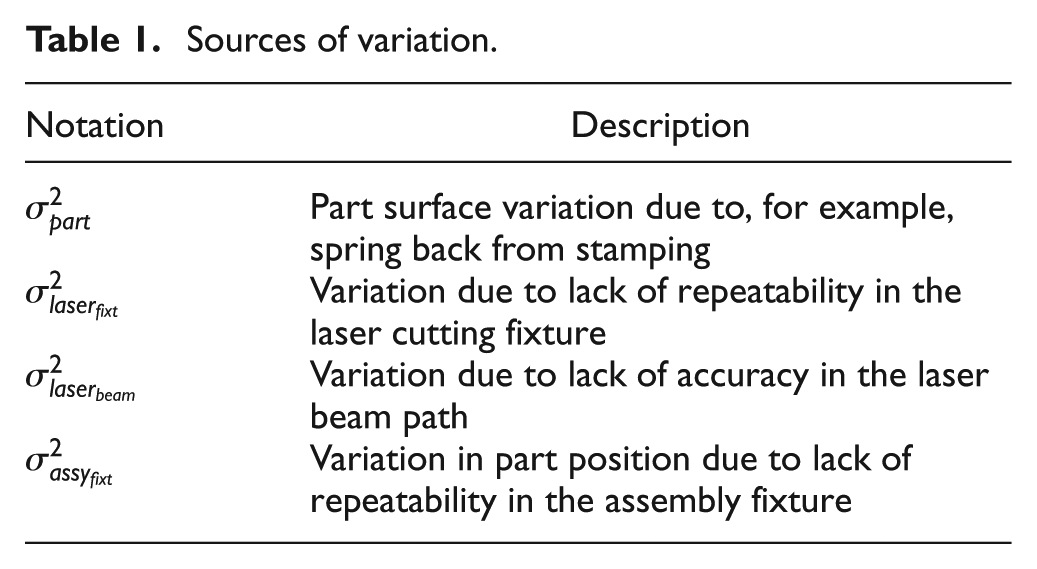
There are several different variation sources present in the sequence of manufacturing operations, described in the previous section. The most significant one is the part variation in normal direction to the part surface, which is a result of, for example, spring back after stamping. Furthermore, there will be variation due to lack of repeatability in both the laser fixture and the assembly fixture. 10 Finally, there will also be variation due to lack of accuracy in the laser beam path; this variation source is, however, assumed to be of a very small magnitude. The different variation sources are summarized in Table 1.
Sources of variation.
There are three main strategies for fixturing of parts during laser cutting (step 2 in the description in previous section). Different strategies lead to different tolerance stack-ups in the laser cutting edges. These strategies are described below using the notation from Table 1.
Strategy 1
In this strategy, the customer locators and locators for laser cutting are manufactured during stamping. The customer locators and the laser cutting locators do not coincide.
The total variation in the laser cut edge X, evaluated during assembly using customer locators, is given as
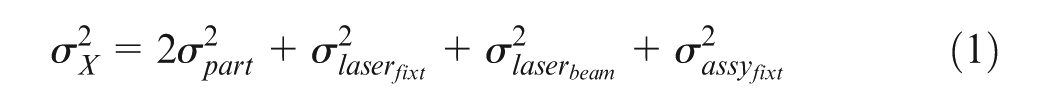
Here, the part surface variation,
The laser fixture variation,
Finally, the assembly fixture variation,
Strategy 2
The customer locators and locators for laser cutting are manufactured during stamping. The customer locators and the laser cutting locators do coincide.
The total variation in the laser cutting edge X is given as
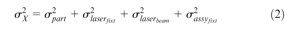
Here, the double effect, compared to equation (1), from part variation is eliminated. The part variation does affect the accuracy when the part is positioned during laser cutting. But thereafter, the relation between the locators and the cutting edge will be maintained during positioning in the assembly station since the same locators are used during laser cutting and part positioning in the assembly station.
Strategy 3
The locators for laser cutting are manufactured during stamping. The customer locators are manufactured during the laser cutting step.
The total variation in the laser cutting edge X is given as
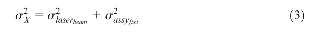
The part variation is completely removed since the part is positioned in the laser fixture, and thereafter, the customer locators and the laser cutting edge are cut in the same setup. This means that the relation between the laser cutting edge and the customer locators will be maintained, no matter how the part is positioned in the laser cutting fixture. For the same reason, also the laser fixture variation is removed.
As outlined above, one source of variation can give rise to different variation contributors for critical features (i.e. the laser cutting edge in this case) depending on the chosen fixturing strategy. These contributors are listed below:
Part surface variation in customer locators (
Part surface variation in laser cutting locators (
Laser cutting fixture variation (
Laser beam path variation leading to variation in the cutting edge (
Laser beam path variation leading to variation in customer locators manufactured during laser cutting (
Assembly fixture variation (
In Table 2, the different contributors for each strategy are listed. Contributors to Strategy 1 are A and B since the part variation is present in both laser cutting locators and customer locators, C and D since the relation between the laser cutting edge and the customer locators is affected both by lack of precision in the laser cutting fixture and by variation in the laser path beam and F since there is variation in the assembly fixture. In Strategy 2, A is no longer a contributor since the customer locator and the laser cutting locators coincide and the part variation in the locators is already taken into account once (contributor B) when the part is positioned in the laser cutting fixture. In Strategy 3, the relation between the laser cutting edge and the customer locators is independent of part variation, so there will be no contribution from part variation (i.e. A or B not contributing). There is, however, a contribution from E since the laser beam variation affects the precision in the customer locators (the holes).
Variation contributors for different strategies.
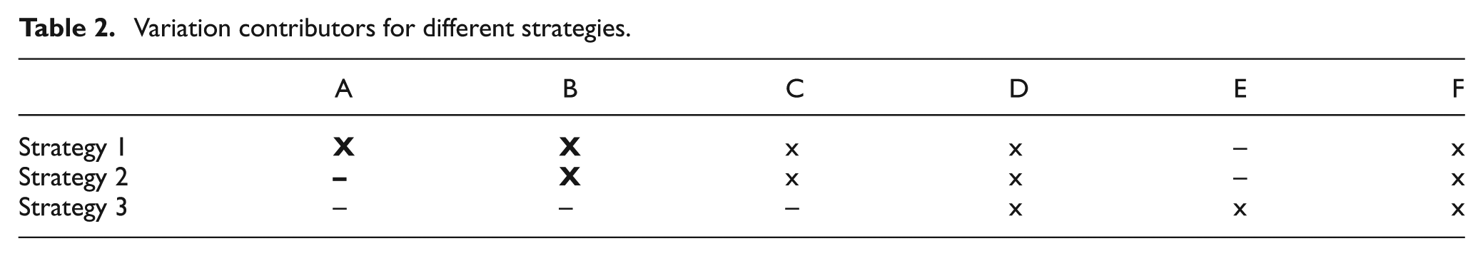
As can be seen, Strategy 1 has five contributors to the total variation in the cutting edge, Strategy 2 has four contributors and Strategy 3 has only three contributors. As outlined in section “Geometrical couplings,” it is important to minimize the number of contributors, and therefore, Strategy 3 is the preferable one. It is, however, also important to take the size of the contributions into consideration. Also from this perspective, Strategy 3 has an advantage since the part variation (contributors A and B) can be assumed to be larger than the fixture and laser beam variations. This is indicated with larger cross marks for A and B compared to the other contributors in Table 2.
Case study
A case study consisting of a C-pillar reinforcement is used to illustrate the three strategies described in the previous section. The part, illustrated in Figure 4, is made of Usibor 1500P, which is high-strength boron steel used to reduce weight and improve crash safety characteristics in modern car design. The C-pillar reinforcement is assembled to the inside of the side panel of the car. The manufacturing of the C-pillar reinforcement follows the steps described in section “Manufacturing of a sheet metal part.” In Figure 5, the locators are illustrated with arrows.
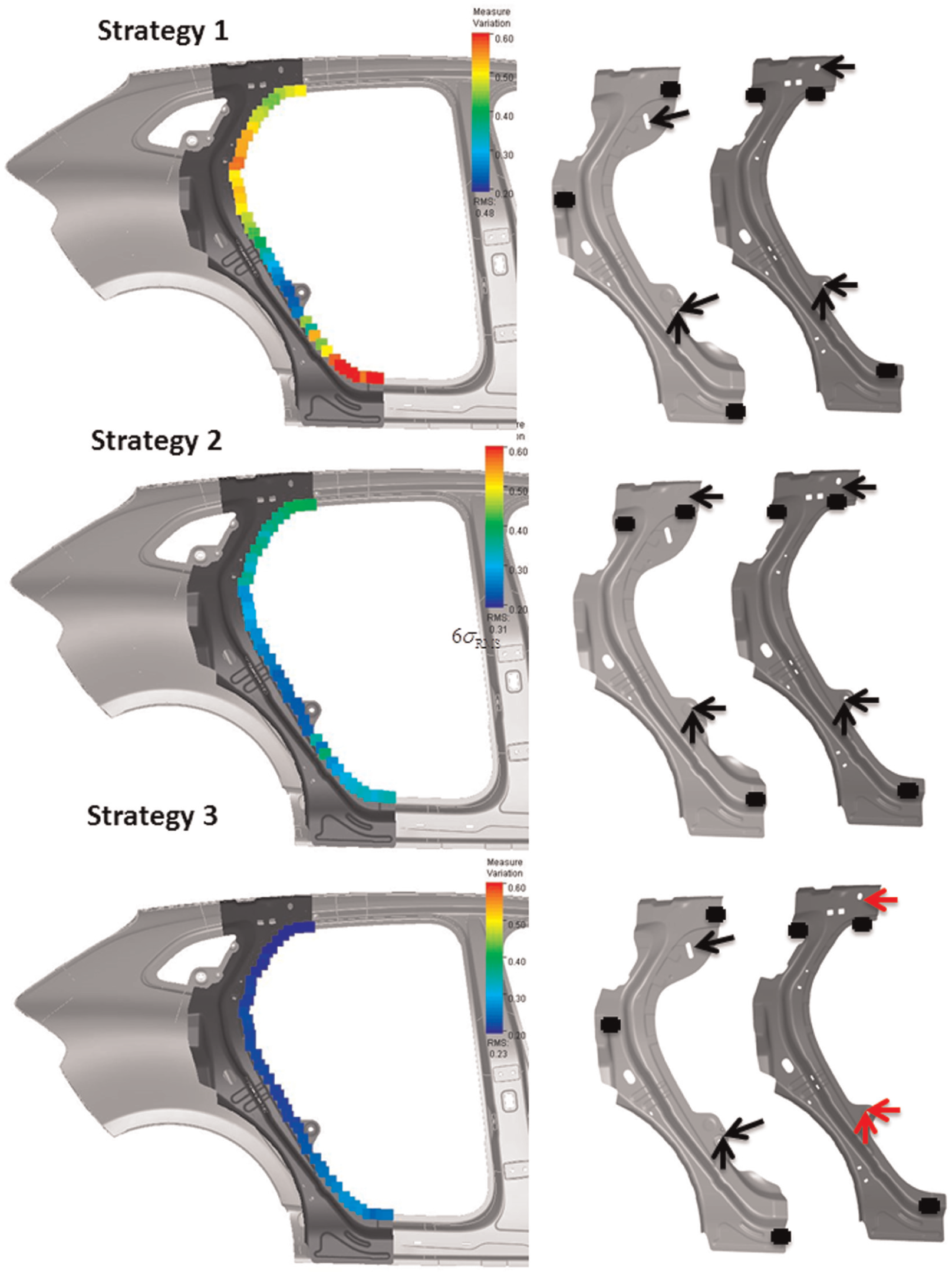
Color coding of the level of variation between the laser cutting edge and the side panel. The same color coding scale is used in all figures, and the minimum value (blue) equals 6s = 0.20 mm and the maximum value (red) equals 6s = 0.60 mm. For each strategy, the locators for laser cutting and customer locators are shown. For Strategy 3, the customer locators are made during laser cutting.
To evaluate the strategies described above, 6s in a seam of measures between the laser cutting edge of the C-pillar reinforcement and the side panel (in total 45 inspection points) is calculated for each strategy. To do this, the variation simulation software RD&T 16 is used. In RD&T, a Monte Carlo–based statistical variation simulation is conducted in order to analyze the tolerance stack up. A total sensitivity matrix is implicitly defined in a finite element analysis (FEA)-based simulation model describing all mating conditions, kinematic relations and non-rigid behavior. The tolerances for the case study, used as input to the simulations, are given in Table 3. The tolerance values for the contributors A, B, C and F are chosen in accordance with normal tolerance values for part surface and fixture tolerances in automotive industry. The values related to the laser beam path, that is, D and E, are assumed to be smaller than the variation in the fixtures. Generally, it can be expected that A, B ≫ C, F > D, E.
Contributor tolerances for the case study.
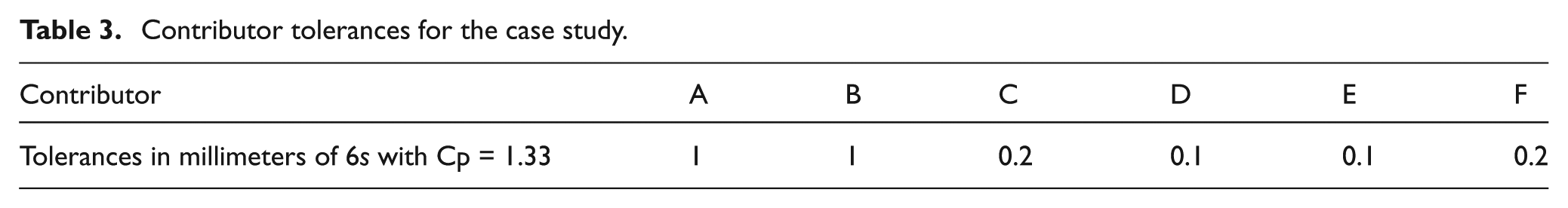
Besides the inputs given in Table 3, a small assembly fixture tolerance (0.2 mm) is also assigned to the assembly fixture of the side panel. This tolerance is present for all three fixturing strategies. All tolerances are assumed to be normally distributed. The results of the simulations for the different strategies can be seen in Figure 5. The root mean square values of 6s for all measures in the seam for the three different strategies are 0.48, 0.31 and 0.23 mm, respectively. So, the case study confirms the conclusion from previous sections.
Discussion
In this section, the results from previous sections are discussed and set in relation to their background. The work presented here is based on the theories of axiomatic design. According to axiomatic design, a good, uncoupled, design is a design where each output is controlled by one and only one input. To achieve this for a physical part manufactured during a sequence of operations, such as stamping, laser cutting and other types of machining processes, the choice of locating schemes is critical. Furthermore, it is important to minimize the number of contributors to the variation in a critical feature. This reasoning led to the development of Strategy 3, explained in previous sections and verified by the case study.
Another important factor is the geometrical robustness of the locating scheme, defined as its ability to suppress variation. By finding a robust locating scheme, the magnitude of the contributors can be minimized. To improve the robustness of a locating scheme, the locating points should be spread over the part in order to cover an area as large as possible. The locating scheme can be evaluated using a variation simulation tool 14 and it can also be optimized with respect to robustness. 17
The results can be generalized into three general guidelines:
The locating scheme should be as robust as possible.
The critical features and their locating scheme should be created during the same operation.
The critical features and their locating scheme (created during the same operation) should be created as late as possible in the sequence of operations in order to preserve the relation between the two.
The first one minimizes the sensitivity to the effects of different variation sources, that is, the magnitudes of the different contributors are minimized. The second one gives an uncoupled solution, where the critical features will be independent of part variation. The third one helps minimizing the number of other contributors (besides part variation) to the total variation in the critical feature.
Conclusion
The aim of this article is to provide guidelines for fixturing during laser cutting of a stamped part. Three different strategies are investigated:
Different locating schemes are used during laser cutting and final assembly. Both locating schemes are created during stamping.
The same locating scheme is used during laser cutting and final assembly. The locating scheme is created during stamping.
The locating scheme for laser cutting is created during stamping. The locating scheme (the hole and the slot) for final assembly is created during laser cutting.
It has been shown, both from a theoretical viewpoint and by using a case study, that Strategy 3 is the superior one. This can be explained by the fact that Strategy 3 has the least number of contributors to variation in the critical features of the part. Moreover, Strategy 3 excludes the effect from part variation, which can be assumed to be the dominant source of variation.
Based on the geometrical reasoning about minimizing the number of variation sources, the magnitude of the variation sources and the case study, three general guidelines can be formulated:
The locating scheme should be as robust as possible.
The critical features and their locating scheme should be created during the same operation.
The critical features and their locating scheme (created during the same operation) should be created as late as possible in the sequence of operations in order to preserve the relation between the two.
In this article, a laser cutting example was used to illustrate the proposed decoupling philosophies. However, the same reasoning can be applied to other sequences of manufacturing operations.
Footnotes
Acknowledgements
This work was carried out at the Wingquist Laboratory VINN Excellence Centre within the Area of Advance Production at Chalmers.
Declaration of conflicting interests
The authors declare that there is no conflict of interest.
Funding
This study was supported by the Swedish Governmental Agency for Innovation Systems (VINNOVA).