
Abstract
Minimum quantity lubrication technology is emerging as a potential alternative to flood cooling to effectively control cutting temperature during machining. In this study, an in-house developed minimum quantity lubrication delivery system has been used for minimum quantity lubrication delivery of cutting fluid at the machining zone. An advanced nanofluid coolant was also used for the purpose of minimum quantity lubrication. Different methods have been attempted to measure the near tool-tip temperature during turning of AISI 4140 steel with multi-layered coated insert under dry, flood cooled and minimum quantity lubrication cooled condition. It was further attempted to identify the best technique for assessing near tool-tip temperature. Infrared thermography has shown the closest result to that obtained through a finite element analysis (DEFORM 3DTM) simulation. Potential of multi-walled carbon nanotube–based nanofluid in minimum quantity lubrication application has been thoroughly investigated in this case study, where high-speed turning of AISI 4140 steel was carried out by a multi-layered coated carbide insert. Design of experiments, based on Taguchi method, was used to find out the significance of cutting parameters on machinability under nanofluid environment. Multi-walled carbon nanotube–based nanofluid was found to outperform the rest in all conditions.
Keywords
Introduction
Minimum quantity lubrication (MQL) technology is gaining its importance and is being used in various high-speed machining applications. 1 A very small volume of cutting fluid is atomised with the help of a high-pressure, high-velocity air jet before being admitted to machining zone. The atomisation increases the total effective surface area of cooling medium to dissipate the heat. Many research attempts have been reported with MQL in many machining processes such as drilling, 2,3 milling 4,5 and grinding 6 –8 and also in turning, which is the focus of this investigation. 9,10 However, a dearth of literature is observed in the area of high-speed turning with multi-layered coated tool under MQL environment, especially with nanofluid. The interaction of tool and workpiece with air-atomised cutting fluid and the ability of the mixture to dissipate heat have been the matter of interest in the literatures. 11,12 MQL not only offers significantly better performance than flood cooling, in a given set of parameters, in terms of more heat dissipation from cutting zone, but also reduces the costs of recycling and filtration of cutting fluid. In terms of enhanced product quality, improved tool life, economy of technological realisation and benign characteristic (depending on the chemical composition of cutting fluid), it is being recognised as a sustainable solution to temperature-related challenges in machining. 13
On the other hand, use of functional coatings, in single-layer or multi-layered architecture, on cutting tools is now a common practice. A literature 14 has shown the effectiveness of coated inserts such as TiC, TiC/TiN and TiC/Al2O3/TiN in terms of cutting force reduction and machining zone temperature reduction. Similarly, Wang 15 has also successfully shown the effect of multi-layered architecture coated insert in reducing turning force in all directions. Khrais and Lin 16 have shown the various wear mechanisms of recently popular TiAlN coating in case of turning AISI 4140 steel. Literatures are very less in number to record the performance of the coated tool in nanofluid MQL environment.
Again, precise measurement of tool-tip temperature has always been a challenge to the researchers, especially when a cutting fluid is applied. Both contact- and non-contact-type devices were used. Abhang and Hameedullah 17 have tried with K-type thermocouple to measure chip–tool interface temperature. Davies et al. 18 have shown various methods and calibration process in different material removal processes. On the other hand, pyrometer and infrared (IR) thermography are used as non-contact-type tools. Brosse et al. 19 have used IR thermography for temperature measurement and heat flux characterisation in grinding. Attempt was also made to monitor the quality (online) of abrasive water jet machining using IR thermography. 20 Selek et al. 21 have used IR thermography in turning for measurement of cooling performance using special vortex tube. Various soft computing tools such as ANSYS, ABAQUS, AdvantEdge and DEFORM were used for analysing the machining zone temperature and predicting other parameters in machining. A report has shown the use of DEFORM software to compute cutting force in machining. 22 Özel and Altan 23 have modelled high-speed machining process of mould steel and predicted tool forces, stress levels and cutting temperatures at different machining conditions. Patrascu and Carutasu 24 have shown the prediction of cutting force for different parametric conditions using virtual machining (DEFORM software).
Nanofluid is a new class of fluids engineered by dispersing nanometer-size solid particles in base fluids to enhance heat transfer capability and tribological properties. It exhibits a potential promise as a cutting fluid in versatile machining applications. But there is a dearth of literature in the area of application of nanofluids in machining. Shen et al. 7 had used alumina nanofluid in MQL grinding area and compared its effectivity with other conventional coolants. Carbon nanotube (CNT) had clearly shown non-linear increase in thermal conductivity with CNT loading and a significant difference between the theoretical and measured values of conductivity. 25 Nam et al. 26 had used nanodiamond particles for micro-drilling operation and had shown the effectivity of nanofluid lubrication in terms of minimisation of thrust force and torque level. Sridharan and Malkin 27 had used MoS2 and CNT nanofluids in grinding and had shown that nanofluids can improve surface quality as well as minimise specific energy significantly. Vasu and Reddy 28 had used alumina nanofluids in turning Inconel 600. They had shown improvement in surface quality, cutting force and tool wear.
This investigation is focussed on revealing the scope and effectiveness of nanofluids, synthesised with multi-walled carbon nanotube (MWCNT) for high-speed machining of AISI 4140 steel by multi-layered coated carbide insert. After selection of proper temperature measurement method, stable MWCNT nanofluid was prepared and used as a coolant in MQL mode to explore the effectiveness of nanofluids compared to conventional coolant. In this work, effectiveness of MQL technology has been investigated, with an indigenously built MQL set-up, in high-speed turning of AISI 4140 steel with a multi-layered TiN top-coated insert. It also proposed a suitable technique to assess the near tool-tip temperature which is an index of average cutting zone temperature. Since the effectiveness of MQL is expected to be immediately realised on reduction of cutting temperature, online monitoring of the same is essential, which is again a very challenging task in case of a high-speed turning operation. A non-contact measurement technique is, thus, preferred to the contact types. An IR thermography imaging technique was implemented to assess the near tool-tip temperature for the interest of this study. Its usefulness was compared with the contact-type measuring devices such as thermocouple and non-contact-type measuring devices such as digital pyrometer. Simultaneously, finite element analyses (FEAs) were carried out to understand the chip and tool temperature in the vicinity of cutting zone. Since Taguchi method 29,30 is a powerful tool for the design of high-quality systems and it provides a simple, efficient and systematic approach to optimise designs for performance, quality and cost, it is used to assess the performance of MWCNT nanofluid in MQL turning in the present investigation.
Development of MQL delivery system
In case of MQL cooling, the cutting fluid is directed to the machining zone in spray mode. The quantity of cutting fluid needed to supply per unit time is very less (generally 50–500 mL/min as defined for MQL). Therefore, proper design of fluid supply system is essential in MQL approach. A spray nozzle serves this purpose. It is a precision device which facilitates atomisation of liquid into a spray. This may be external or internal mixing type. But lifespan of an external mixing nozzle is more and back pressure development–related disturbances are less compared to the others. In this work, external mixing nozzle has been used for delivery of cutting fluid and the same is visualised in Figure 1. Different parts of the nozzle are shown in Figure 2 for more clarity about its functional objectives. The nozzle has two way inlets. One is for cutting fluid and the other for compressed air. The channel for cutting fluid is at the centre of the nozzle. The entered compressed air is first accumulated in a circular cavity zone, and from there, it is sent to the atmosphere with the help of two circular slots.
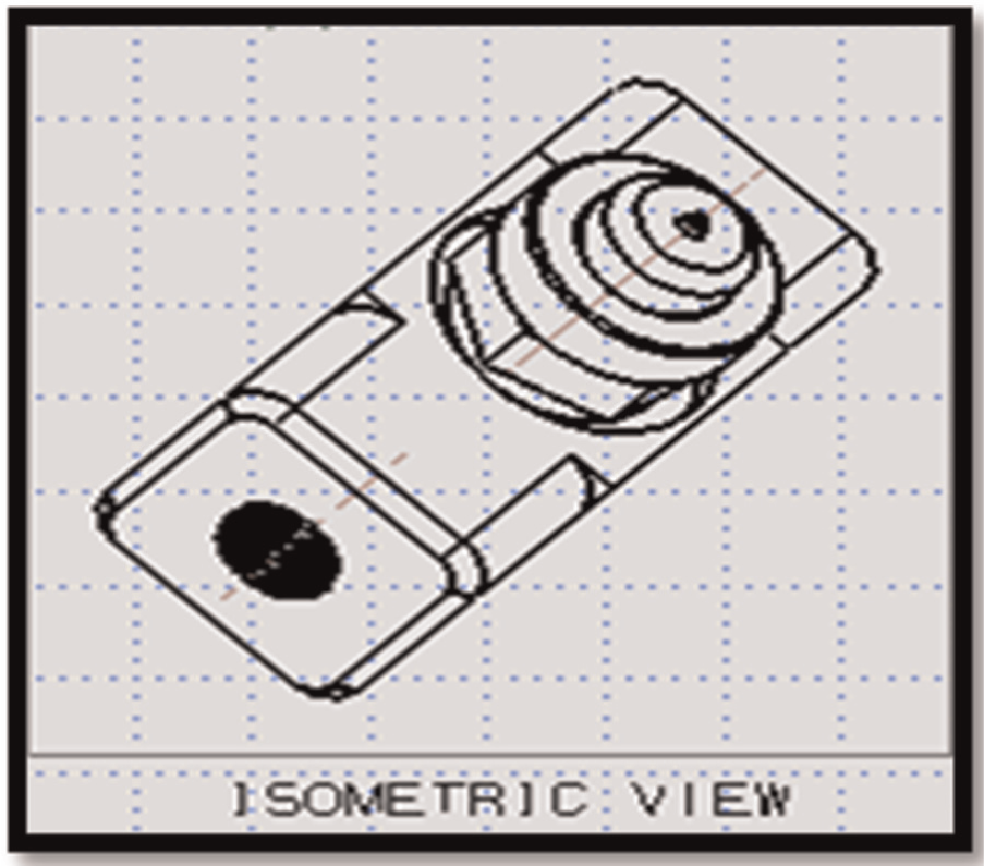
Assembly view of nozzle.
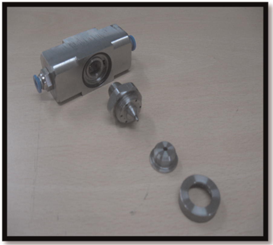
Different parts of nozzle.
Ultrasonic inspection of coated tool
Ultrasonic immersion testing (Figure 3) was done for both TiN- and TiAlN-coated inserts before machining to detect any in-built flaw. Both the inserts were kept side by side and were probed with the help of ultrasonic sensor from top. It is known that sound wave can go through any object unless there is a flaw (e.g. a crack) in the medium. The ultrasonic probe had 5 MHz frequency with 0.5 in diameter and 2 in point focal length. As the inserts were multi-coated, there was possibility of the presence of flaw due to residual stress inside or within the layers of coating. It was so necessary because any flawed tool might always lead to misinterpretation of machining data. Gated C-scan imaging was also done for the inserts to be used for machining. As the insert was 4 mm thick, four gates were selected, each 1 mm thick for the ultrasonic immersion testing. Thus, four gated C-scan images were received. However, no flaw or pilling was found. The sample signal from the TiN-coated insert, in Figure 4, clearly depicts that there is no pilling. Basically with the help of A-scan imaging, information can be achieved for each point of the insert, and by C-scan imaging, layer-by-layer information can be achieved.
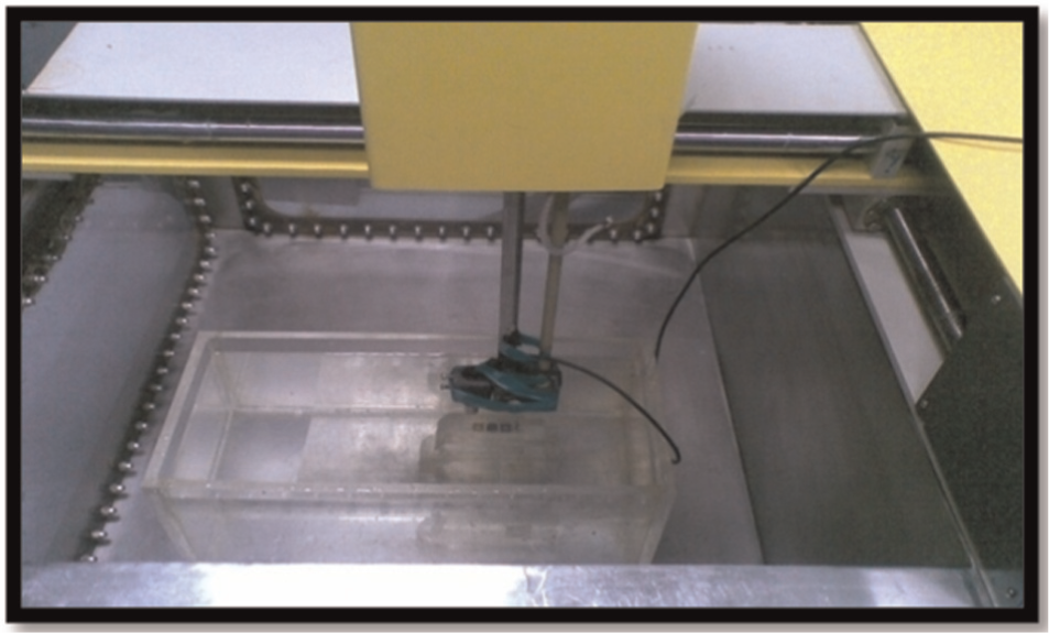
Set-up for ultrasonic inspection of tool.
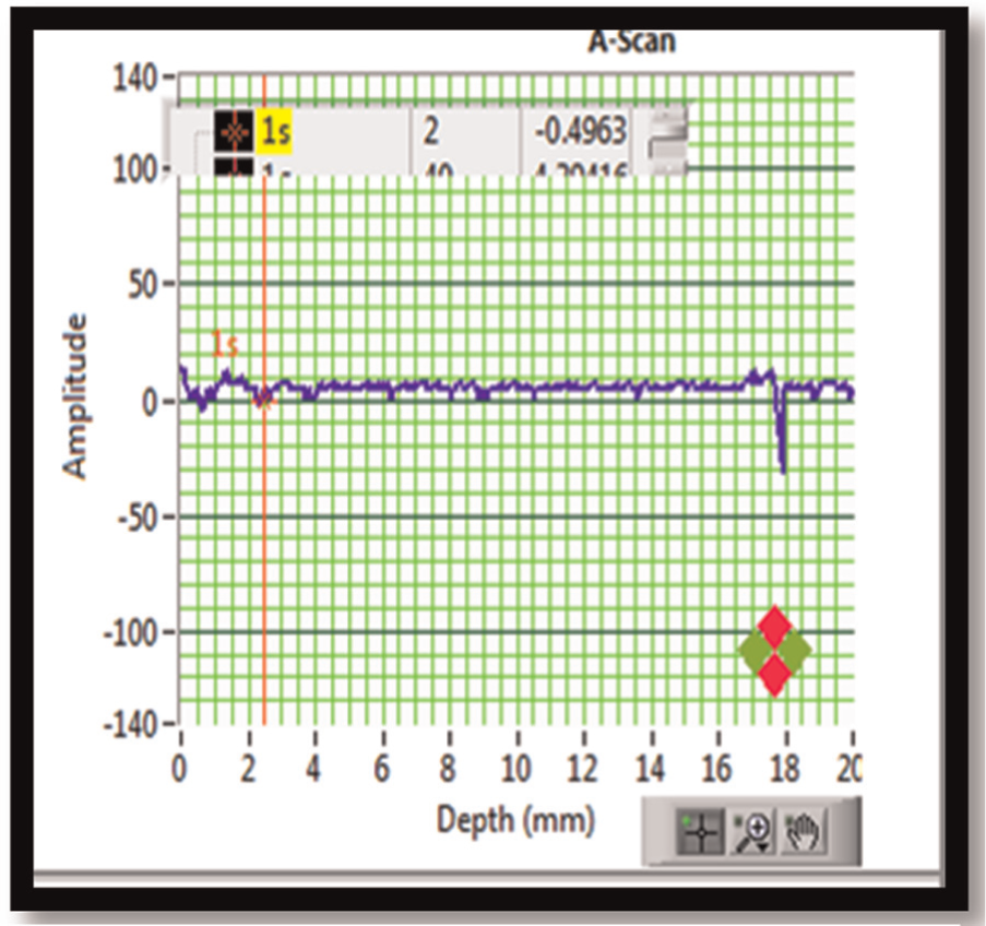
A scan signal.
Experimental procedure and conditions
An in-house developed MQL delivery system was employed in the turning operation, which ensured a minimum delivery rate of 500 mL/h cutting fluid in the cutting zone (Figure 5). The higher extreme flow rate in MQL domain was chosen because there was adverse report in lower extreme flow rate MQL condition. The other experimental parameters are mentioned in Table 1. A flawless, multi-layered TiN top-coated insert, which is, anyway, the recommended one for machining such a material, was used. IR thermography set-up, as visualised in Figure 5, was initially calibrated before use during machining. Videos were taken by an FLIR® camera at 200 frames per second. After that through a dedicated software, post-processing of acquired data is done to assess the near tool-tip temperature. Under dry, flood cooling and MQL environment, machining was conducted.
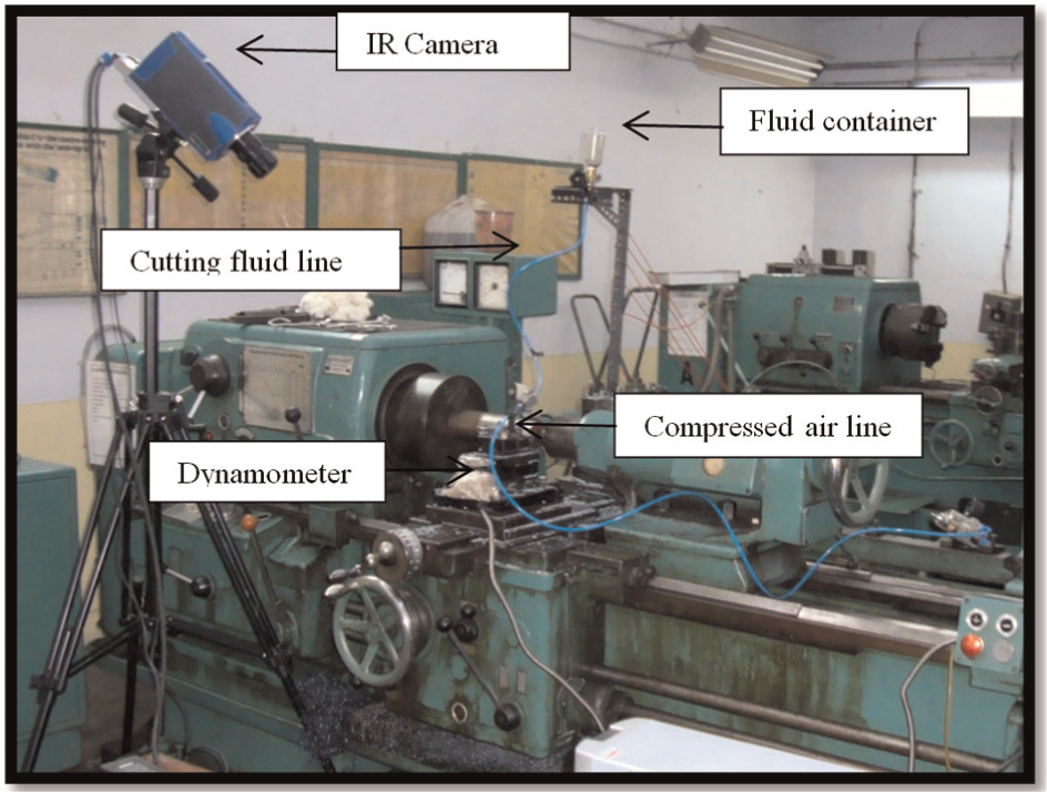
Experimental set-up of MQL turning and temperature measurements by IR-thermography.
Experimental conditions.
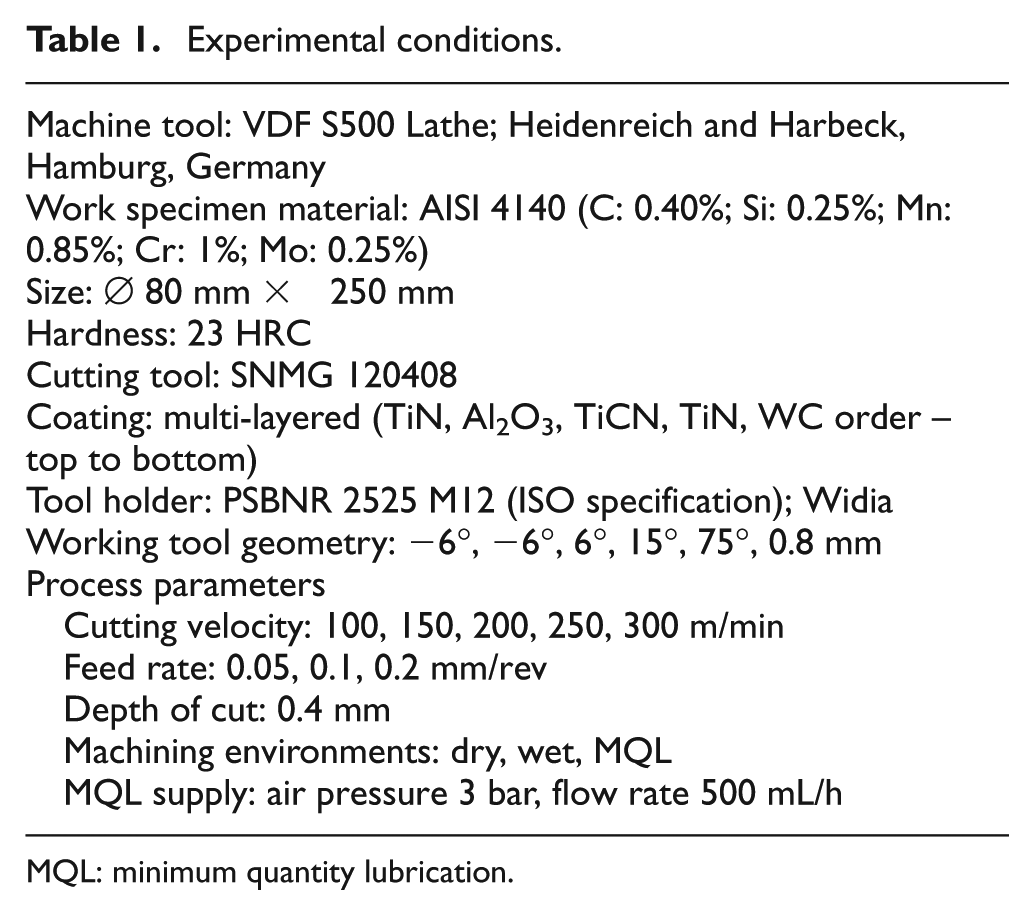
MQL: minimum quantity lubrication.
In IR thermography, before commencing experiment, emissivity was calibrated to a fairly approximated extent. The coated surface was glossier, and the emissivity of the main component of that insert (Ti) was less than 0.5. Thus, the coated insert’s thermal image showed lesser value compared to the non-coated one in non-calibrated condition. From the database, emissivity value of Ti was collected and that value was used during offline recording of temperature of those inserts. The thermal image of the inserts was calibrated initially at atmospheric condition. Also while post-processing the image, a diagonal line was drawn along the insert to observe the temperature variation along the tool. Since the insert’s main component was titanium (TiN-coated insert), its emissivity was calibrated previously. It was seen from the database that for the polished titanium at 149 °C–649 °C, emissivity value was in the range of 0.08–0.19. In the present study, emissivity constant was kept as 0.12 because the maximum temperature was expected to be well below 649 °C.
As shown in Figure 6, for this study, K-type thermocouple has been used. With the help of suitable adhesive, thermocouple was stuck at the closest zone of tool tip. For pyrometer technique, IR ray was focussed on the tool tip and dynamic value of the temperature at tool-tip zone was recorded. Both IR thermography and pyrometer techniques are non-contact methods, whereas thermocouple technique is contact-type method for temperature assessment. With the most befitting technique, the usefulness of nanofluid in reduction of cutting temperature was assessed later. Finally, after getting proper benefit in tool-tip temperature reduction, CNT nanofluid was used again for getting optimum cutting parameters and the whole experiment in best cutting condition was modelled properly.
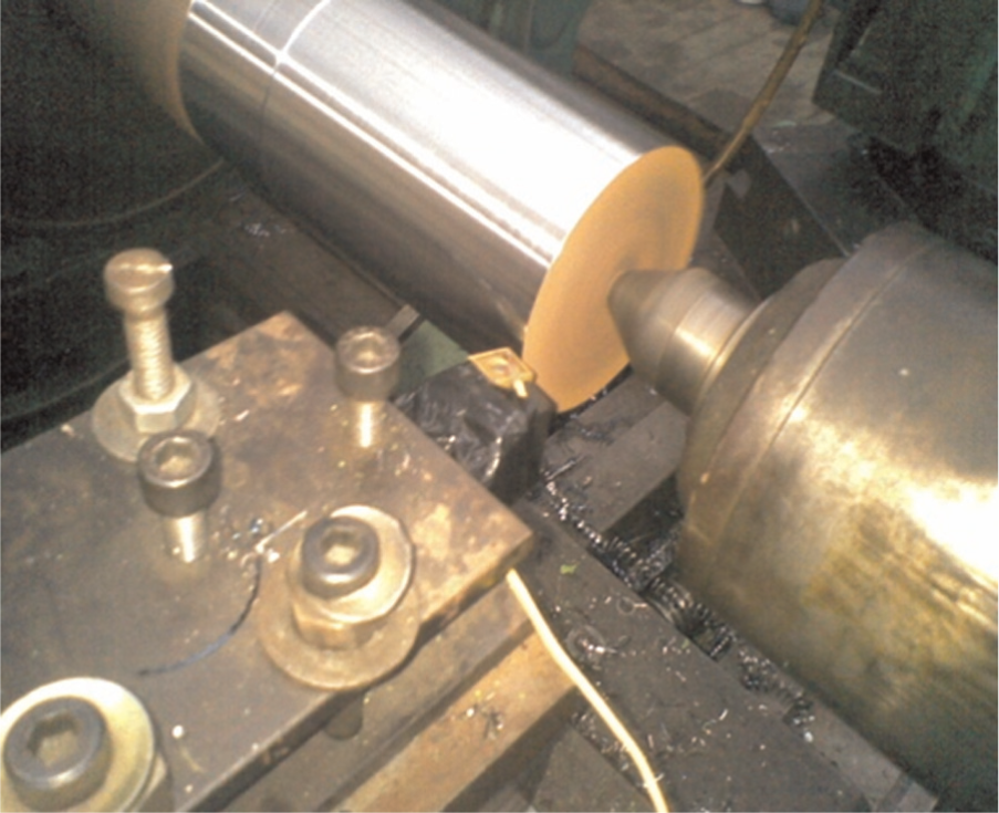
Thermocouple technique for temperature measurements.
Results and discussions
Figure 7 clearly indicates the difference in measured temperature level for a specific feed rate and depth of cut at various cutting velocities under dry environment. All the results show more or less increasing tendency of tool-tip temperature with increased cutting velocity. This was due to more cutting power consumption at higher cutting velocity and hence more heat flux across the chip–tool contact area. Figure 8, through an IR thermographic image, depicts the intensity of heat at the cutting zone with respect to its surroundings. A selected area, say near the tip of tool, was zoomed and thermal analysis was done on it. Results of IR thermography analyses were further compared with the results obtained using thermocouple and digital pyrometer at a given cutting condition.
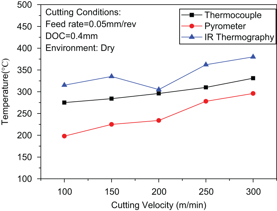
Different techniques for temperature measurements.
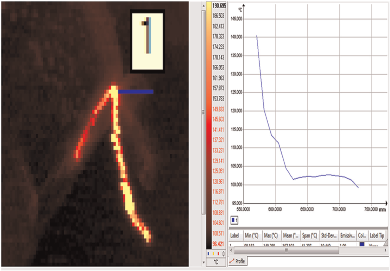
Tool-tip temperature measurements using IR thermography.
It was observed that the temperature data from the IR thermography technique were best comparable with FEA results (discussed later). It appears that it was difficult to keep the digital pyrometer focussed on and thermocouple fixed to the nearest point (zone) to tool tip avoiding the chip when it was flowing at high velocities and there was every possibility of minor change in its direction. On the other hand, IR thermography data could be carefully post-processed to select a zone on the tool, nearest to chip. Multiple frames could be consulted immediately before and after a given time to assess the near tool-tip temperature. Figure 8 reveals such an analysis on a particular frame. This IR thermography technique was alone used for the MQL experiment for being the most precise approach.
Figure 9 clearly brings out the difference in near tool-tip temperatures with increasing cutting velocities under different environments including MQL with conventional coolant and nanofluid lubricated condition. It reflects the obvious increase in temperature with cutting velocities due to increase in heat flux. The effectiveness of MQL environment appears to be more pronounced than that of the other environments. Also from Figure 9, we can understand that the temperature generation at tool–work zone is the lowest in MWCNT-lubricated condition. The main reason is that due to very high thermal conductivity (~3000 W/mK at 300 K), MWCNT can absorb more heat compared to conventional coolant which results in decrease in temperature of around 30%−35% compared to dry cutting condition. The recorded data appeared as the minimum at all cutting velocities when nanofluid MQL was used. This significant reduction of near tool-tip temperature clearly establishes technological benefit of the nanofluid MQL technology in this investigation, that is, high-speed turning of steel with multi-layered coated insert with TiN top coating.
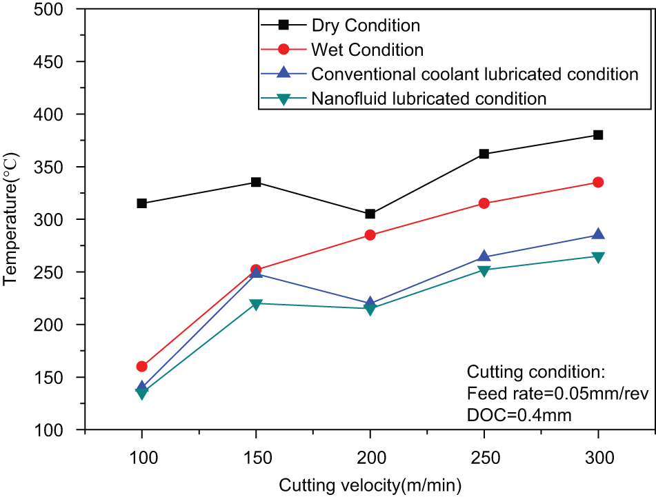
Tool-tip temperature in different cutting conditions.
It is known that by increasing the cutting velocity, the tool–chip interface temperature will rise. In Figure 7, the temperature drops between the cutting velocity range of 150–200 m/min. The same phenomenon happens in Figure 9. The main reason behind this is sometimes, at higher cutting velocity, due to chip clogging between tool tip and workpiece, tool tip gets lesser time to be in contact with workpiece and thus results in lesser temperature generation in tool tip. This is not a regular phenomenon, but it may happen during experiment.
Machining simulation using DEFORM 3D software
DEFORM 3D is an FEA tool by which turning process can be simulated for same work–tool combination. For dry condition, the turning simulation was done for 300 numbers of steps. The input parameters were cutting velocity 150 m/min, feed rate 0.05 mm/rev and depth of cut 0.4 mm; multi-layered coated insert with tungsten carbide base material was modelled (Figure 10), and material properties of alloy steel AISI 4140 were loaded from DEFORM database. After a proper meshing, database for the problem was generated (Figure 11), and after simulation at a specific number of steps, the chip–tool interaction was post-processed, and from that a significant idea was achieved about the average temperature at tool–work interaction zone and the tool tip.
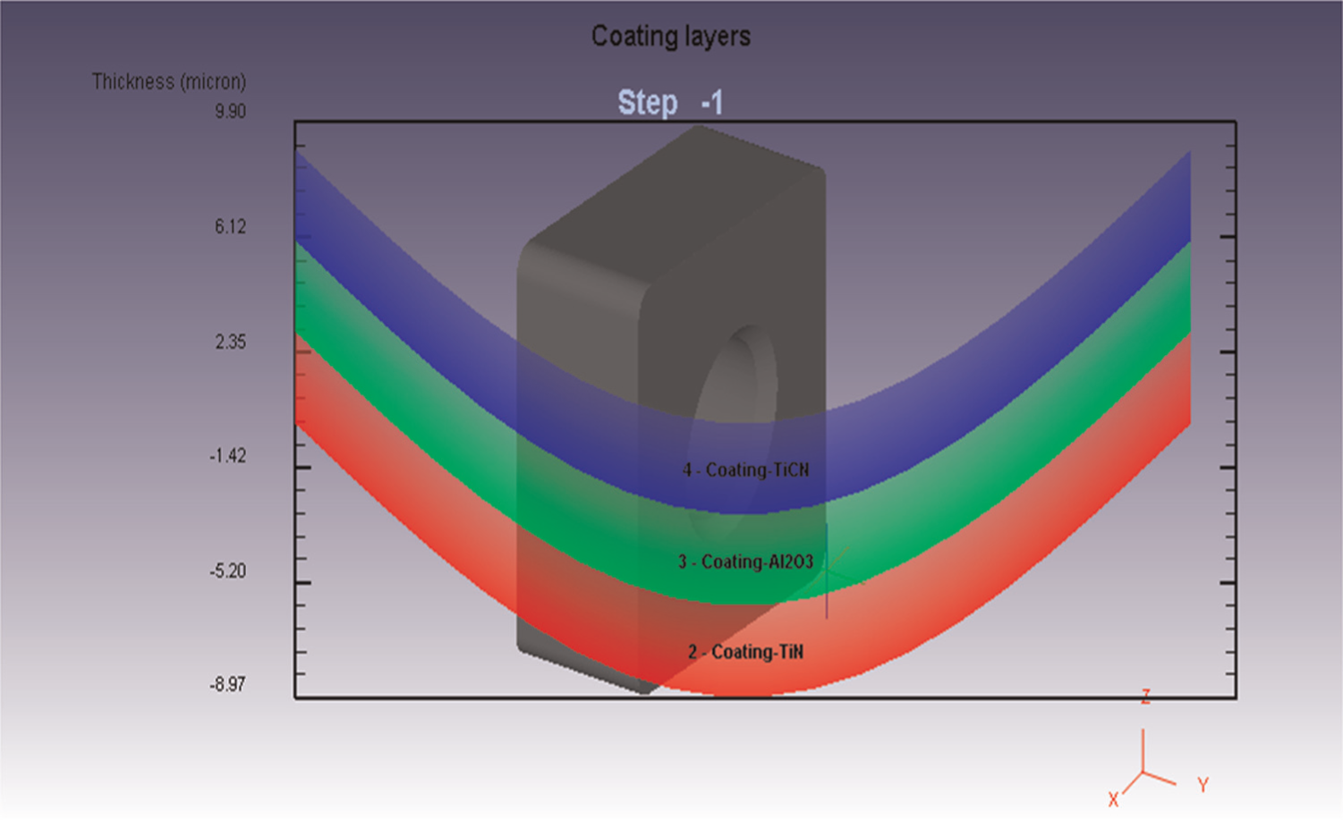
Multi-layered coated insert for turning.
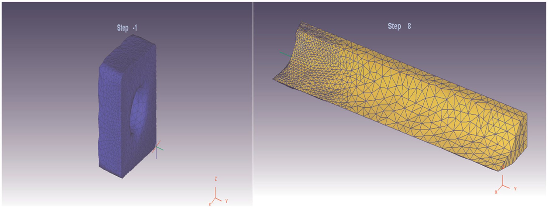
Meshing of coated tool and modelled workpiece.
Thus, the whole procedure includes specifying the process data and loading the materials, inserts and tool holders from the library. From Figure 12, we can observe that for this particular case, the average temperature is in the region of 370 °C–400 °C which is very close to the result opted from IR thermography technique. Thus, thermocouple and pyrometer results had shown more error according to the result opted from the simulation study.
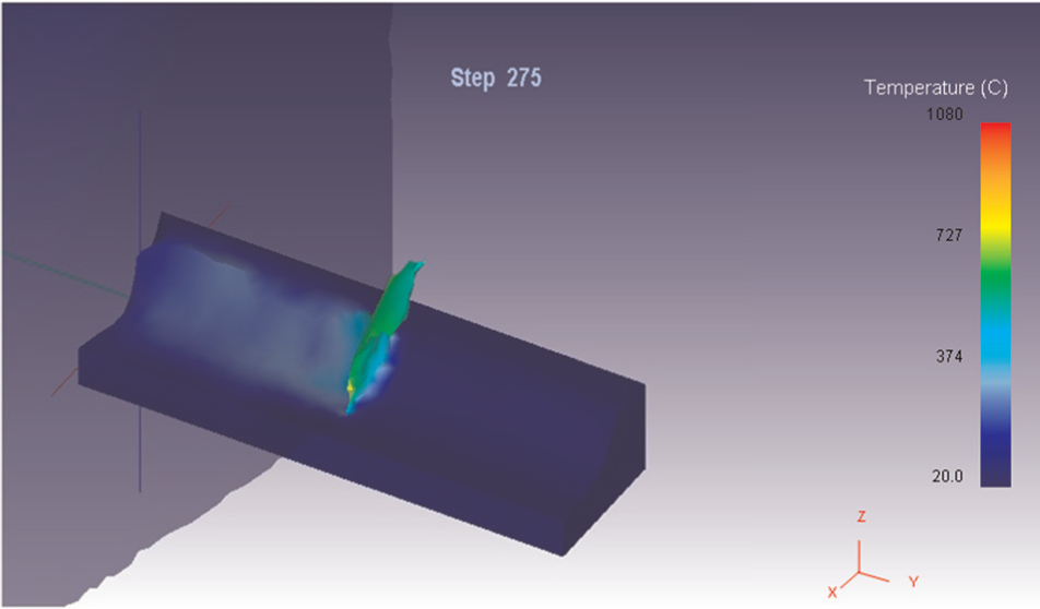
Temperature profile at specific cutting condition using DEFORM software.
Design of experiments in nanofluid turning
In a turning operation, it is an important task to select cutting parameters to achieve high cutting performance. For this study, design of experiments using Taguchi method is opted for getting the optimum parameters as well as significance of each parameter on cutting force in MWCNT nanofluid lubricated condition because this condition had shown the best result from the point of view of force study. Usually, the desired cutting parameters are determined based on experience or by use of a handbook. However, this does not ensure that the selected cutting parameters have optimal or near-optimal cutting performance for a particular machine and environment.
To select the cutting parameters properly, several mathematical models based on statistical regression techniques or neural computing have been constructed to establish the relationship between the cutting performance and the cutting parameters. Then, an objective function with constraints is formulated to solve the optimal cutting parameters using optimisation techniques. Therefore, considerable knowledge and experience are required for using this modern approach. Furthermore, a large number of cutting experiments have to be performed and analysed in order to build the mathematical models. Thus, the required model buildings are very costly in terms of time and materials. In this article, an alternative approach based on the Taguchi method is used to determine the desired cutting parameters more efficiency. The methodology is valuable when the design parameters are qualitative and discrete.
Experimental results and data analysis
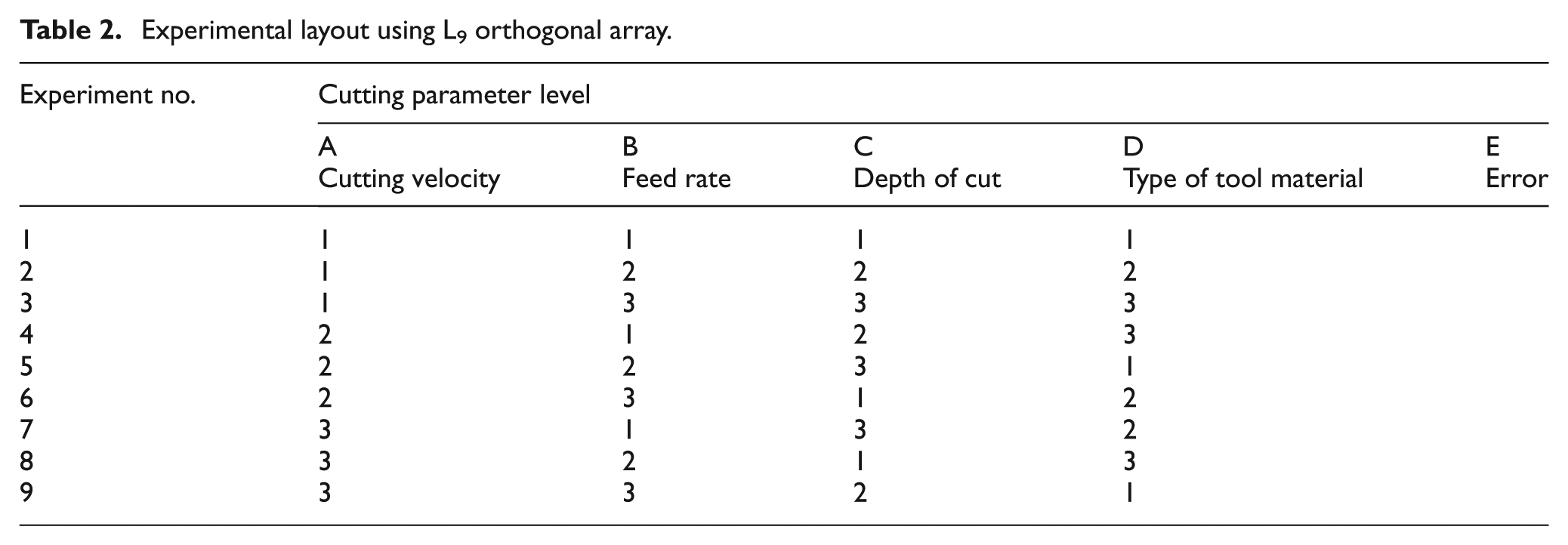
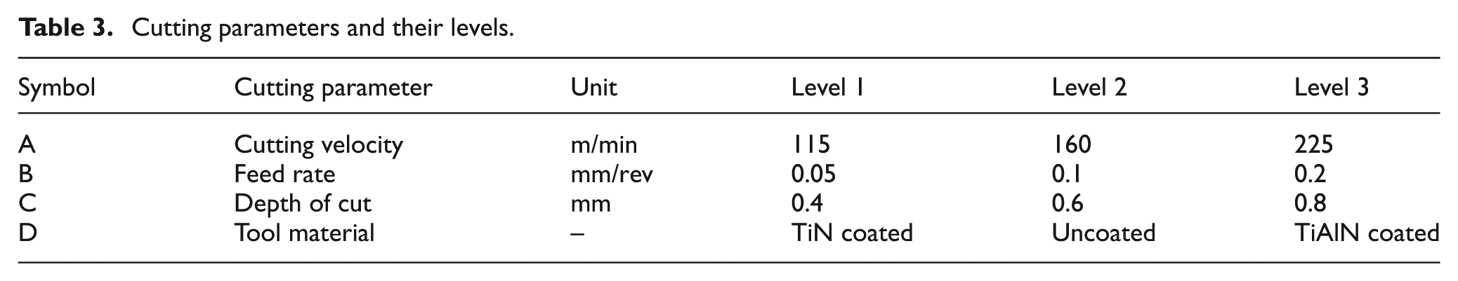
In Table 2, schematic layout of turning experiment is given. Previously, performance study of nanofluid in turning operation was done. So, from the results of that study, it is seen that MWCNT nanofluid lubrication condition had given the best result for the specified turning operation. For in-depth investigation, turning is performed in L9 orthogonal array with MWCNT nanofluid (1 vol%) to identify optimum parameter levels. There were some constraints on choosing the cutting velocity. Other parameter levels are chosen considering the capability of machine tool and ease of machining. Not only speed, feed and depth of cut but also tool type has significant impact while machining. So, this parameter is also included in this study (Table 3). Although, there are so many other parameters such as pressure of compressed air supply. Flow rate of nanofluid and so on could be varied, but those parameters are not included in this study to simplify the effectivity of other parameters in turning. So, for whole experiment, the pressure of air supply is kept constant at 3 bar, and the flow rate of nanofluid is kept constant at 500 mL/h.
Experimental layout using L9 orthogonal array.
Cutting parameters and their levels.
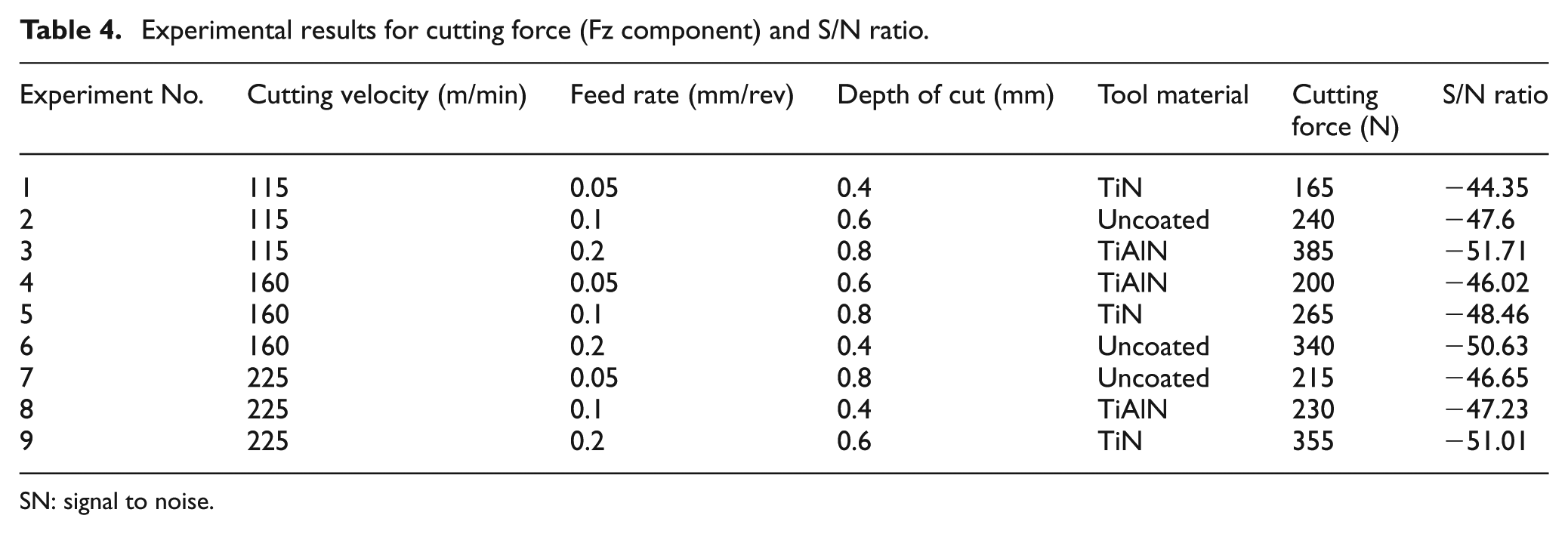
From Table 4, the signal-to-noise (S/N) ratio for cutting force result of each condition is calculated on the basis of ‘smaller is better’ quality characteristics. In Table 5, the mean S/N ratio for each parameter at each level is calculated as the arithmetic average of the S/N ratio obtained from Table 4. From Table 5, it is seen that the difference in maximum and minimum values of S/N ratio is maximum for feed rate and minimum for tool material. This depicts that in the performed turning operation, cutting force component is monitored mainly by feed rate of the machining operation, whereas tool material and cutting velocity have a very minimum impact on the cutting force data compared to feed rate or depth of cut. But to accurately predict the contribution of each factor, analysis of variance (ANOVA) is needed. The results of ANOVA are given in Table 6. Also, from Table 5, we can infer that A1B1C1D1 combination is the optimum condition for getting cutting force to be a minimum value.
Experimental results for cutting force (Fz component) and S/N ratio.
SN: signal to noise.
S/N response table for cutting force (Fz).
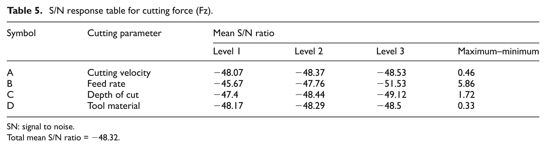
SN: signal to noise.
Total mean S/N ratio = −48.32.
Results of analysis of variance for cutting force.
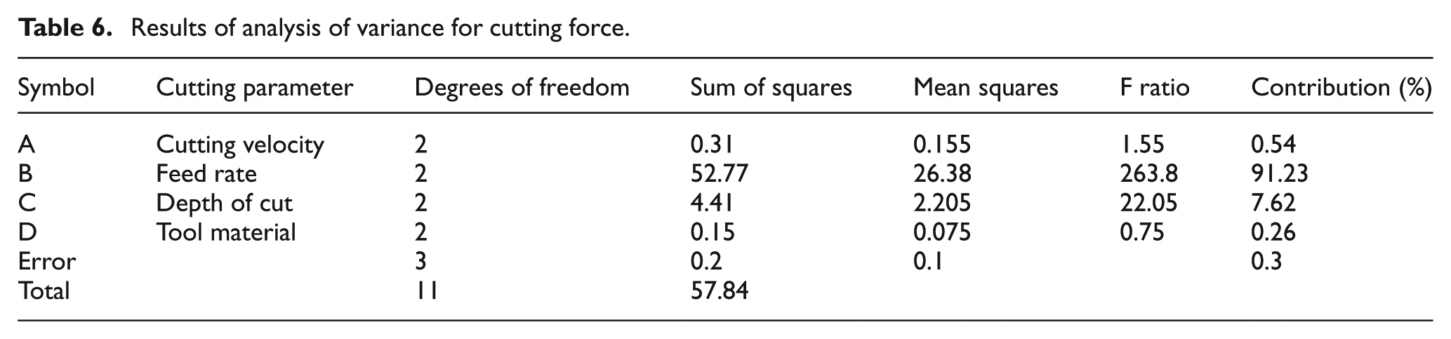
From Table 6, it is seen that cutting force component is mainly monitored by feed rate of machining, having its contribution more than 90%. The second contributor is depth of cut (7.62%). Also, the cutting velocity and tool material have a very minimum impact on cutting force component compared to feed rate and depth of cut. Figure 13 also depicts that the effect of feed rate is maximum on cutting force. So, to decrease the cutting force, we need to choose the feed rate value properly.
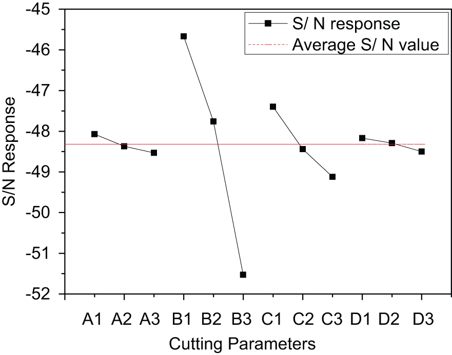
S/N graph for cutting force (Fz).
The main objective of the experiment conducted based on Table 7 is to check whether any better S/N ratio can be obtained by using predicted optimum cutting parameters. Since levels 1 and 3 are extreme levels, all the cutting parameters are either in minimum or maximum range. If we would take those as initial values, then we may or may not get proper effect of usage of predicted optimum parameters. To be on the safer side, we had chosen level-2 parameters as initial parameters for the confirmation test and this reason has been included now. Finally, confirmation test for optimum condition is done with initial cutting parameter level A2B2C2D2 and optimum cutting parameter level A1B1CD1. In predicted optimum parameter level, an improvement of 3.7 dB in S/N ratio was achieved (Table 7). Thus, A1B1C1D1 condition can be predicted as the best fitted condition from the point of view of cutting force.
Results of confirmation test for cutting force (Fz).
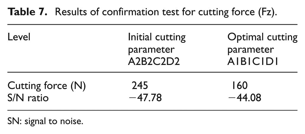
SN: signal to noise.
Conclusion
Indigenously developed MQL delivery system could ensure a flow rate of cutting fluid at approximately 8 mL/min, which falls under a minimum quantity range.
Effect of MQL technique was realised in terms of temperature reduction. It had shown better cooling compared to dry and flood cooling turning operation. In MQL condition compared to flood cooling condition, 10%−30% decrease in near tool-tip temperature was observed.
IR thermography technique could be most successfully used to assess near tool-tip temperature under different conditions.
IR thermography results were the closest to the FEA results than thermocouple and digital pyrometer results. Approximately 10% difference was observed in measurement of temperature using thermography compared with the simulation result for same operating conditions.
Nanofluid MQL lubrication has shown better heat-absorbing characteristics compared to conventional coolant lubrication.
Design of experiments using Taguchi method is successfully used to model the whole experimental conditions in best cutting condition after having a comparative study of near tool-tip temperature under different machining environments.
Footnotes
Declaration of conflicting interests
The authors declare that there is no conflict of interest.
Funding
This research received no specific grant from any funding agency in the public, commercial or not-for-profit sectors.