
Abstract
The method of embedded cold-pressing joining could achieve the joining of sheets with different thickness and the joining of dissimilar sheets. Besides, it could meet the lightweight request easily. This article expounded the joining mechanism of this method deeply. To expound the joining mechanism of this method, this article has taken aluminum and stainless steel as examples. In addition, numerical stimulation studies of different hole types’ connecting processes had shown that it was easier to reach plastic yield conditions for aluminum and deform it under the same load conditions. The deformation achieved was significantly greater than that for stainless steel. The width increment of the joining parts increased with the increase of the load pressures; however, the thickness changes of the joining parts behaved in an opposite manner. When the pressing volume of the punch reached 2.4 mm, with the width increment of aluminum sheets of the square hole reaching 2.78 mm, which was the maximum width increment, followed by the hexagonal hole, and the round hole being a minimum. Hole type had a small influence on the width of stainless steel sheets. The experimental results of different hole type joining process indicated that compared with round hole and hexagonal hole, the filling of the square hole was relatively difficult. In case of unreasonable process schemes, defects such as “fake joining,” “offset loading” and “hole deformation” would occur. Thus, this article provided a theoretical basis for the scheme establishment and quality control of the embedded cold-pressing joining process.
Introduction
With the increasing application of aluminum–magnesium alloys and high-strength steels in automotive, aerospace and other fields, the problems related to joining of different materials has become one of the hot topics of discussion in aerospace and automotive industry. 1 He 2 indicates that riveting is an effective mechanical connecting technique, and there are many scholars studying this method further by simulation and experimental techniques. Roux and Bouchard 3 optimized the technique of clinching by Kriging meta-model. Some other scholars researched on the effect of technological parameters and metal mechanical properties on quality of connection and morphology. Lambiase and Di Ilio 4 analyzed the material flow of extensible dies by finite element analysis (FEM). The increasing of punch force and the sheet thickness led to connection axial asymmetry. Kim et al. 5 found that the connection load decreases with increase in the connection temperature. Han et al. 6 researched the sheet pre-straining of self-piercing riveted aluminum alloy sheet and discussed the relationship between it and the static and fatigue behavior. This article shows that shear and fatigue strength increase with increase in the pre-straining level. Mucha et al. 7 analyzed the influence of the thickness distribution and die on connection strength. Mucha 8 studied it further and discussed the effect of process parameters on high-strength steel, and found that the die radius, die depth and die groove shape are mainly parameters and Lee et al. 9 researched the relationship between process parameters and connection characteristics. Shi et al. 10 projected a tool design method that is used for the designing of clinching tools. Masters et al. 11 present a simulation method that can forecast deformation process of self-piercing rivet. These discussions and designs improved the rationality of design and elevated the development and application of clinching tools.
This article proposes a new mechanical connection method, and researches on the method of embedded cold-pressing connecting further, and analyzed the effect of crucial technical factors on the joining quality with numerical simulation and technology experiments.
Research scheme
Principle
Through-holes of a certain number and geometry (e.g. round, square shaped, etc.) need to be prefabricated in the teeth on one side of the end portion of the sheet in the embedded sheet cold-pressing deformation joining process. Then the prepared sheet is matched and lapped with the end of another sheet section by section before putting them on the press workbench. Then, the sheets are put on the press workbench, and as the punch moves down and a load is applied on the joining region, the end portion deforms and interlocks; in this way, the embedded deformation joining is realized; the principle is shown in Figure 1.
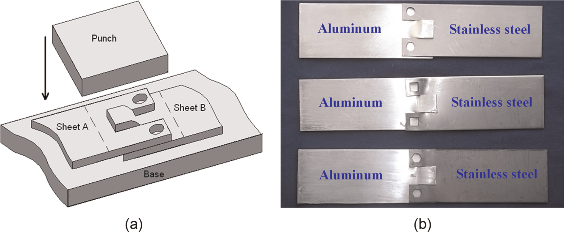
Principle of embedded cold-pressing joining: (a) schematic diagram of joint principle and (b) design of hole type.
The analysis of strength theory has shown that, under the same load conditions, lower strength material reaches plastic yield and deforms first. So the holes are processed on the high-strength sheet, while the lower strength sheets are deformed and embedded into the holes to obtain deformation joining.
Embedded cold-pressing joining method has the following salient features: it can be used in joining same or dissimilar sheets and sheets with same or different thicknesses, independent of the sheet size; has low sheet surface quality requirements, and there is no need for polishing; has relatively low technology and equipment demands and has low cost and is easy to be implemented in production. Therefore, the method is easily applied in production. Compared with mechanical joining methods such as stamping joining, it can improve the normal direction carrying capacity of the joint.
Research approach
Finite element software DEFORM-3D is employed in this article, and FEM has been taken as finite element analysis. Defining the connected sheets as elastic–plastic finite element model, the materials used are 304 stainless steel and 1100 aluminum, which are processed into rectangles 80 mm in length, 30 mm in width and 1.15 mm in thickness. The punch, the base and the other auxiliary tools are defined as rigid bodies. In order to save operation time and ensure accuracy of operation, this study takes axial symmetry model as a research object of simulation due to the symmetry of connection sheets, and imposes restriction on symmetry plane to ensure that speed is zero in width. The friction between the sheets and the mold is defined by the Coulomb friction model with friction factor of 0.12. It defines punch downward movement by speed of 1 mm/s.
The experimental materials are the same as numerical simulation. As per the aforementioned analysis, different holes are processed on the stainless steel sheets at one of the end portions in advance. The type and size of the hole have an important impact on the quality of joining. The three holes’ types involved are shown in Figure 1(b). In order to facilitate comparing, the diameter of the round hole, the edge length of the square hole and the inscribed circle diameter of the hexagonal hole are all 5 mm.
The experiment is performed on the universal testing equipment with the forming speed of 0.5 mm/s. There are many process parameters affecting the joint quality. Therefore, comparisons are made under load pressures of 200, 250 and 290 kN, when the other process conditions are settled. The chemical composition of sheets is shown in Table 1, and mechanical properties are shown in Table 2.
Chemical composition.
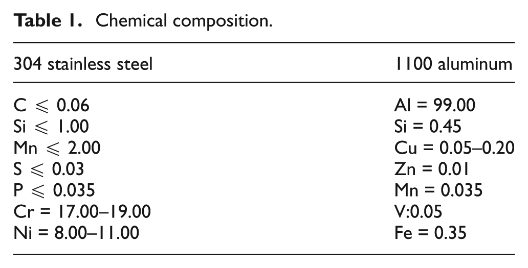
Mechanical properties.
σb: tensile strength; σ0.2: offset yield strength; δ: elongation.
Analysis of embedded joining process
Embedded joining behavior
After applying normal pressure to the joining regions, the low-strength sheet of the joining regions is stuffed into the holes of the other sheet. The comparison of the stainless steel sheet and aluminum sheet stuff flow behavior during joining process is shown in Figure 2, taking round hole process as an example.
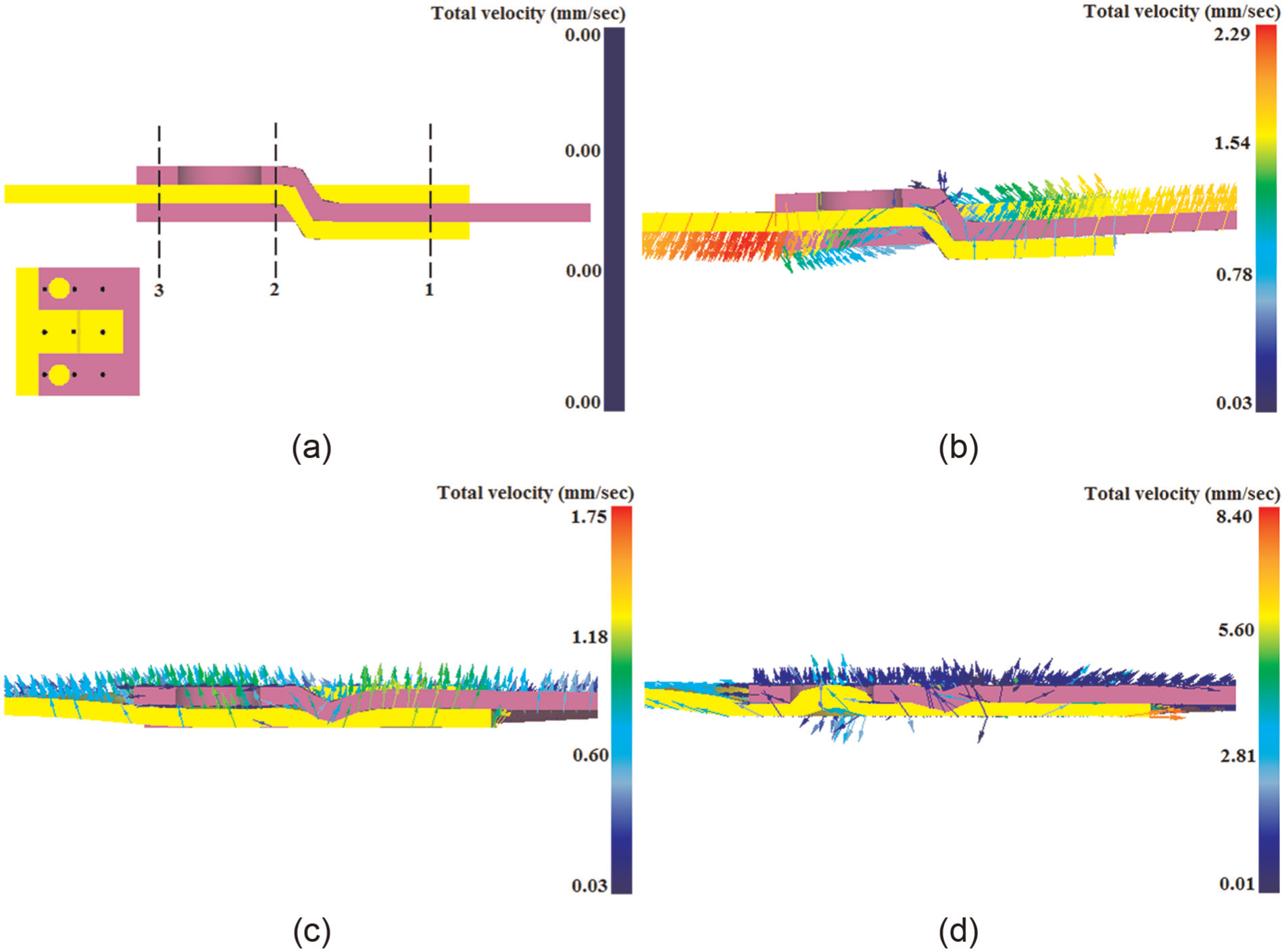
Behavior of the embedded cold-pressing joining: (a) 0, (b) 0.2, (c) 2 and (d) 2.6 mm.
It can be seen from Figure 2(a) that the two sheets are put on the workbench without being pressed after pre-processing, and then are matched and lapped. The stress of the joint region becomes extremely unbalanced when normal load is applied, and the sheets’ positions change due to instability. The initial forming stage is shown in Figure 2(b). The left top side of the joint region touches the punch, while the right bottom side of the joint region is next to the workbench. When normal pressure is applied, the sheets of the joint regions deflection move because of the existence torque effect. Meanwhile, the left side and the right side show significant trend of deforming and flowing downward and upward separately, and the flow velocity of the edges on the joint region is much higher than that of the middle part. As shown in Figure 2(c), the convex tooth in the overlapping position of stainless steel sheet and aluminum sheet deforms and flows toward the opposite side, reaching almost the same horizontal level as the non-overlapping parts. The stress also becomes balanced relatively. The deformation flow tendency of the whole joint region is basically the same, but it is opposite to the load direction. The final forming stage is mainly an embedded deformation joining phase, as shown in Figure 2(d). The aluminum sheet flowed toward and filled the holes in stainless steel sheet, and the aluminum near the holes had a tendency to flow to the deformation region, and therefore, the flow velocity of this region is much higher than other regions, and the thinning of the aluminum sheet is very significant. After holding the pressure for a long time, the holes are mainly stuffed by the aluminum sheet, and then the embedded joining process is completed.
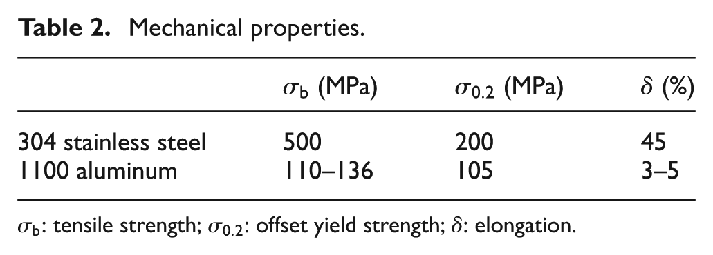
During the joining process, the sheets flowed along the inside direction. Figure 3 shows the comparison of different sheets end portion flow velocity vector distribution in the square hole scheme.
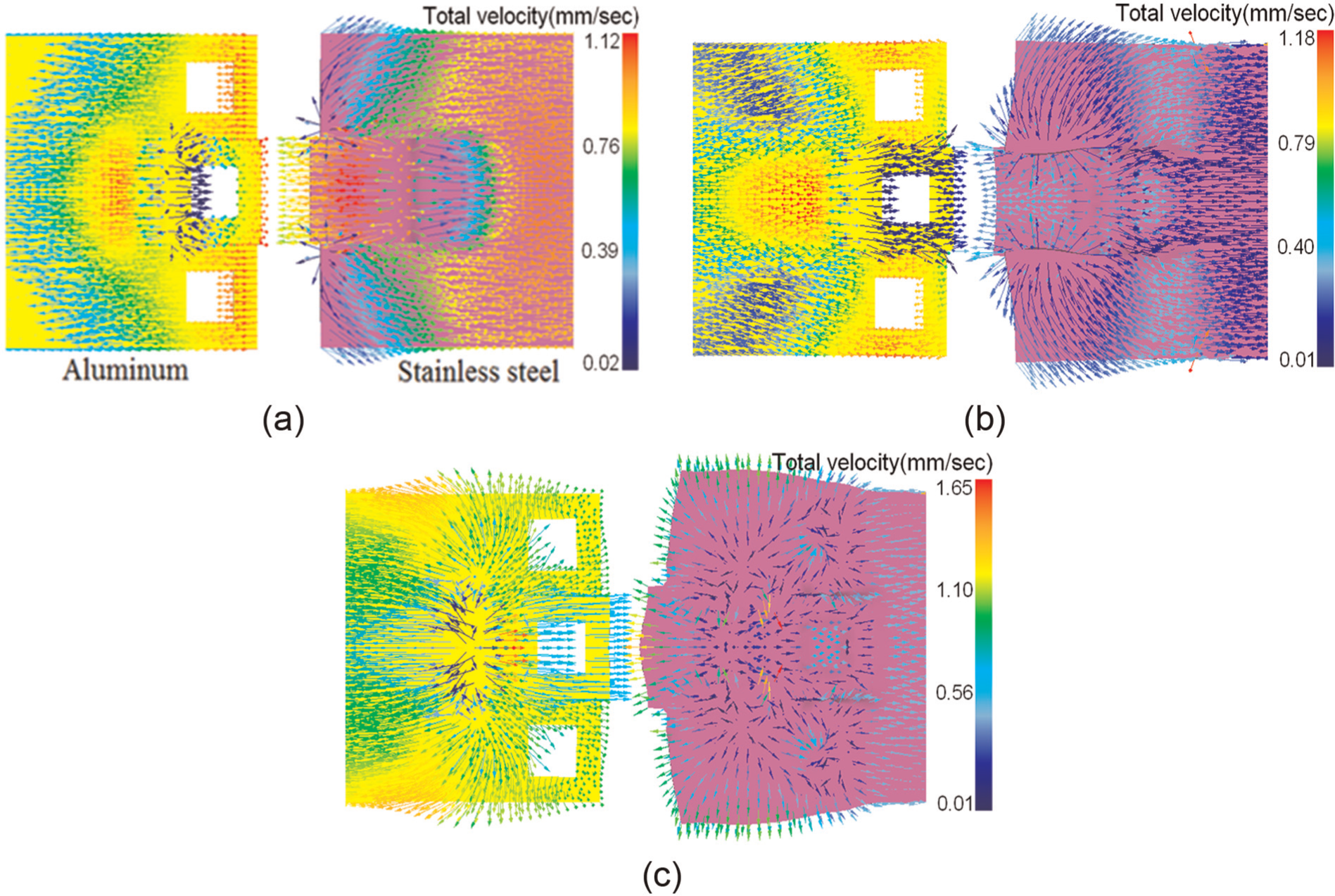
Analysis of the joining portion velocity field: (a) 1, (b) 2 and (c) 2.4 mm.
It can be seen from Figure 3(a) that when the pressing volume of the punch is 1 mm, the unconnected regions of the sheets have a tendency to flow away from the joining region. The middle convex tooth of the stainless steel sheet flows to the other side along the length direction, while the flow of the convex teeth on the two sides is the opposite. The middle convex tooth of the aluminum sheet also has a tendency to flow to the other side, and the convex teeth on the two sides where deformation occurred not only flow along the length direction but also along the vertical length direction. As shown in Figure 3(b), when the pressing volume of the punch is 2 mm, the amount of aluminum deformation is large, and there is a contact with the stainless steel sheet. Meanwhile, the deformation flow tendency of the whole stainless steel sheet is the same as the former, but the flow behavior of different parts on the aluminum is quite different. The deformation flow of the middle convex tooth is mainly along the length direction due to the restrictions on both sides. The convex teeth on both sides flow along the width direction change as left and right shunt trends. While the pressing volume of the punch reaches 2.5 mm, as shown in Figure 3(c), the end portion of the stainless steel sheet tends to flow along the width direction with the obvious increasing of deformation, because of deformation increasing significantly. The width direction deformation of the end portion on the aluminum further increases; moreover, the end portion deforms along the length direction as well. Therefore, the whole region is like a sector. Meanwhile, the aluminum sheet tends to flow into the holes.
The characteristics of the joining deformation
The embedded deformation joining process can be divided into three phases: the adjusting phase, pressing phase and embedding phase. The deformation of different materials is quite different because the material yield strength is different. The comparison of the maximum effective strain influence in joining processes of different hole scheme is shown in Figure 4(a). Maximum effective strain is the maximum value of effective strain at the hole on connected sheets. Maximum effective strain is determined by both pressure and resistance to deformation.
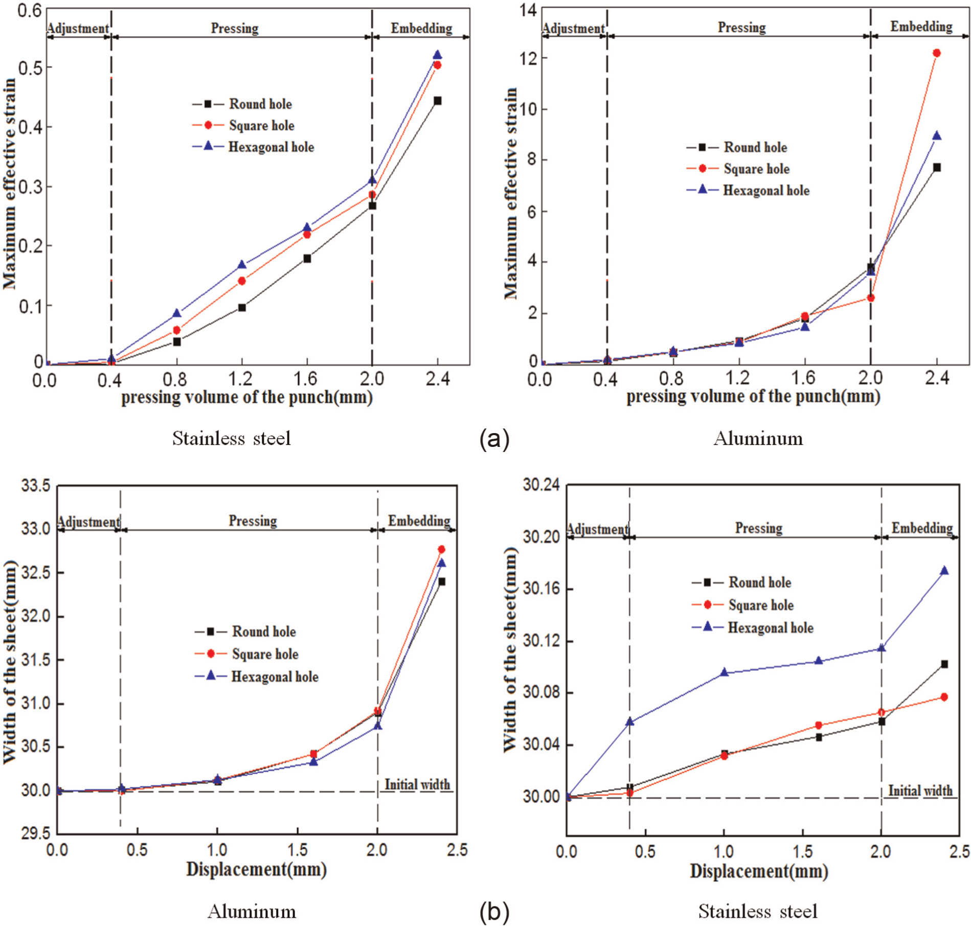
Comparison of the effective strain and the joint width change at the joint region: (a) maximum effective strain and (b) maximum joint width of the joint region.
It can be seen from Figure 4 that the effective strain of the joint region tends to increase with the increasing pressing volume of the punch. The maximum effective strain of the stainless steel sheet will not change before the punch stroke reaches 0.4 mm, as shown in Figure 4(a). After the pressing volume of the punch head reaches 0.4 mm, the maximum effective strain starts to increase significantly, and it comes into the pressing phase. The maximum effective strain of the stainless steel sheet continues to increase during the embedded phase. The stainless steel sheet deforms, while the aluminum sheet embeds into the holes. The comparison indicates that the deformation of the hexagonal hole scheme is the maximum, followed by the square hole and then the round hole. Because of the low strength, the maximum effective strain of the aluminum sheet is more than 10 times that of the stainless steel sheet. During the adjusting and the pressing phases, the maximum effective strains of the aluminum sheets in different hole schemes increase. When displacement punch reaches 2 mm, the maximum effective strain, the width of sheet and the slope increase, which indicates the end of the pressing phase and beginning of the embedding phase. The increase in the degree of maximum effective strain of the aluminum sheets is larger than before in the embedding phase. Analyzing from the numerical comparison, the effective strain of the square hole scheme is the maximum, followed by the hexagonal hole, while it is smallest for the round hole. The maximum effective strain of the stainless steel of the hexagonal hole is more than that of the square hole due to the effect of both pressure and resistance to deformation.
The change of the joint width is shown in Figure 4(b). The initial width of the sheets is 30 mm, and the joint width increases as the normal load increases. Before the movement of the punch reaches 0.4 mm, the aluminum sheets are moved mainly to adjust the position; therefore, almost no change occurs in the aluminum sheet along its width. When the pressing volume of the punch reaches 1.6 mm, the width size increases to 30.4 mm. When it reaches 2.4 mm, the width size keeps increasing. Among them, the width size of the square hole scheme increases by 2.78 mm, which is the maximum, followed by the hexagonal hole and round hole. The width deformation of the stainless steel sheets is much smaller than that of the aluminum sheets, but the hole style has more influence on the width size change of the stainless steel sheets. When the pressing volume of the punch reaches 2.4 mm, the width size of the square hole scheme and the round hole scheme increases by 0.07 and 0.10 mm, respectively, while it is up to 0.17 mm in the hexagonal hole scheme. As a result, it can be concluded that the hexagonal hole process of the stainless steel sheet had the maximum elongation along the width direction under the same loading conditions.
The load changes of the joint region
From the former analysis, embedded cold-pressing joining method can be broadly divided into three stages, and the deformation flow of the three phases is quite different, which causes the load change. The sheets’ joint load of different hole styles is compared in Figure 5.
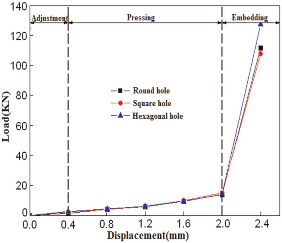
Comparison of changes in joint load.
The load of sheets joined with different hole styles tends to increase. Combined with the former analysis, the whole deformation is less in the adjusting phase, and it mainly adjusts the location. Therefore, the joint load is small, less than 1 kN. When it comes into the pressing phase, convex teeth of two sheets deform to the other side gradually and are coated, while the sheets’ deformation volume is larger. So, the need of deformation load is significantly more than the adjusting phase. When the pressing volume of the punch increases from 0.4 to 2.0 mm, the joint load of different hole styles increases from 3.28 times to 3.81 times. In the embedding stage, the increase of required joint load is great because of the need to increase the amount of aluminum deformation and to overcome the resistance of prefabricated holes on the aluminum sheet. When the pressing volume of the punch increases from 2.0 to 2.4 mm, the joint load of different hole shapes increases from 7.14 times to 9.03 times, and the joint load at the hexagonal hole scheme is up to 130 kN.
Consequently, the hole type has little influence on the joint load, especially in the adjusting and the pressing phases, the changing tendency is almost the same. The joint load of different hole shapes in the embedding phase has almost no difference. Among them, the joint load of the hexagonal hole scheme is a bit larger than the round and the square scheme.
Experimental
Joining process
The processed samples are put on the presses bench, then the punch head is moved downward to apply normal load to the joint region, as shown in Figure 6. Fixture can be used in advance to make convex teeth of two sheets at the joint region to fit for improving the smoothness of the sample that has lap match.
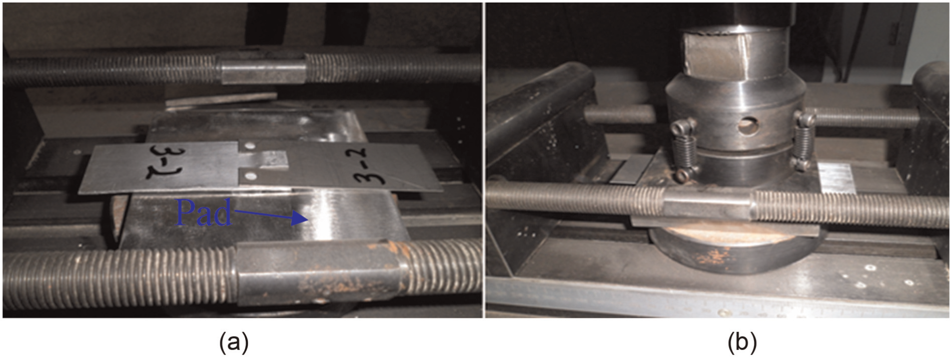
Sheet embedded deformation joining process experiments: (a) sample placement and (b) load.
A pad can be used between the punch and the sheets, so that the load can effectively and uniformly transmit to the joining portion. It not only increases the load area but also avoids the possibility of sheets warping when under load. But defects occur when the technology parameters are unreasonable because there are many factors which affect the quality of embedded cold-pressing joining. Among them, the hole type is one of the most important technology parameters which not only has a significant influence on the joining quality but also affects the embedded joining depth. The contrast of experimental results of different hole shapes in embedded cold-pressing joining is shown in Figure 7.
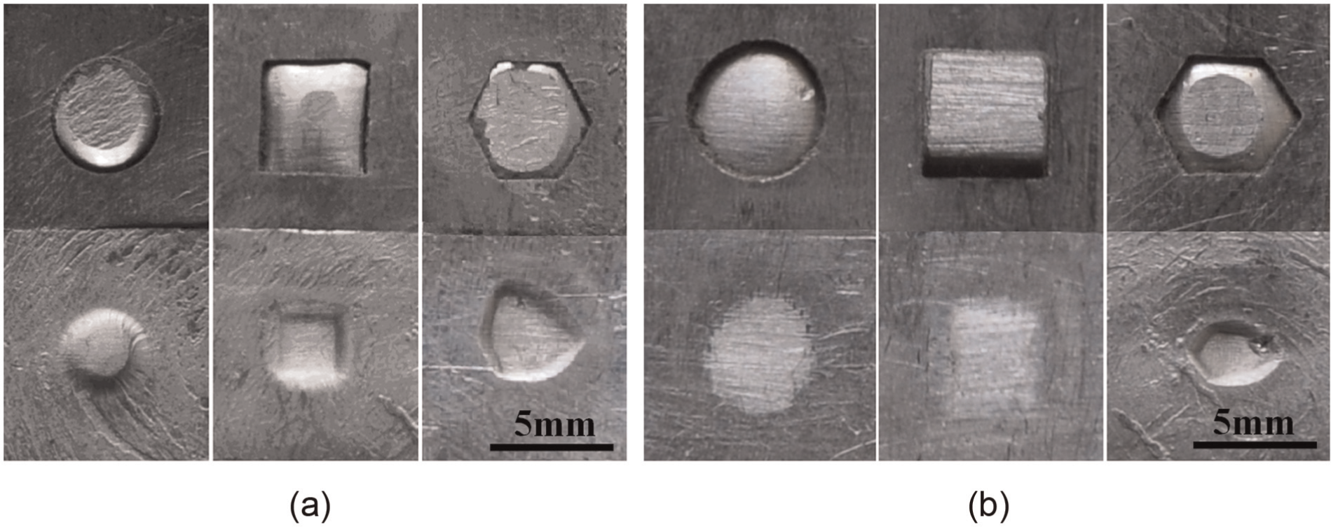
Comparison of different hole type filling morphology: (a) well and (b) not satisfactory.
It can be seen from Figure 7(a) that the stuffing results of different hole types are quite different under the same load conditions. The stuffing of round and the hexagonal scheme is full, while the stuffing of square scheme is relatively difficult because of the resistance around the corners. As can be seen from the concaves on the back of the sheets, the holes mostly filled with aluminum alloy and the shapes of the concaves are similar to the shapes of the holes. However, undesirable results occur when the process is designed unreasonably, as shown in Figure 7(b). Among them, the stuffing amount of the round hole scheme is little, and the deformation is flexible because of the insufficient pressure. The phenomenon is called “fake joining.” So it cannot bear the shear load, and the joining will be destroyed easily. Square hole scheme shows “offset loading.” One side of the hole is barely filled with metal, which cuts down the bearing load markedly. “Hole deformation” preformed in the hexagonal hole scheme is a result of the excessive normal load. It is not very regular that sample back filling characteristics and the sheets are easy to fall off, moreover the holes are easy to break after long-term use.
In order to avoid the undesirable phenomenon and improve joining quality, the finite element simulations are used to optimize the process to make the program best before carrying out the experiment. It can also avoid the defects of “fake joining” and “hole deformation,” which result from insufficient and excessive normal load separately. Meanwhile, in order to avoid “unbalanced-partial load,” the joint region can be flatted or loaded upside down.
Connected shapes and thickness distribution
The stuffing deformation occurs in the joining process. Besides, the interface morphology of joining interface between the convex teeth and the sheets has changed, as shown in Figure 8.
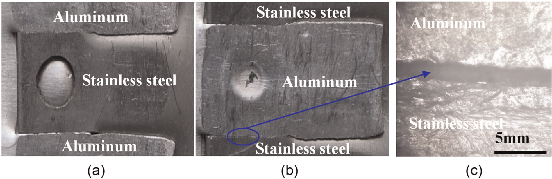
Convex teeth and joint portion morphology: (a) front, (b) back and (c) connecting portions.
It can be seen from Figure 8 that the convex teeth and the regions around change significantly when normal load is applied. When the load reaches a certain value, the convex teeth on the stainless steel sheets will be embedded into the aluminum sheets. The convex tooth roots of the aluminum sheets on the same side deform along the horizontal direction, and when pressed, the convex tooth of the stainless steel sheets is embedded because of the pressure. Meanwhile, the holes on the stainless steel sheets are embedded by the aluminum sheets and the interlocking of the sheets is obtained. This is completely in conformity with the simulated result of Figure 2(d).
The yield strength of the aluminum is lower than that of the stainless steel sheets. As shown in Figure 8(b), the plastic deformation of aluminum sheets appear first under the same load conditions, while the deformation amount of the stainless steel sheets is relatively small. The deformed convex teeth on the stainless steel sheets and the two sides of the tooth are on the same plane, so the joints are smooth, and the sheets are joined closely, as shown in Figure 8(c).
The deformation of the sheets increases significantly with the load increasing and the joint thicknesses reducing. The thickness is the average of the of three equidistant points which are taken along the width direction at sectional portion, as shown in Figure 2(a), and comparison of the relationships between thickness and the pressing load with different hole schemes is shown in Figure 9.
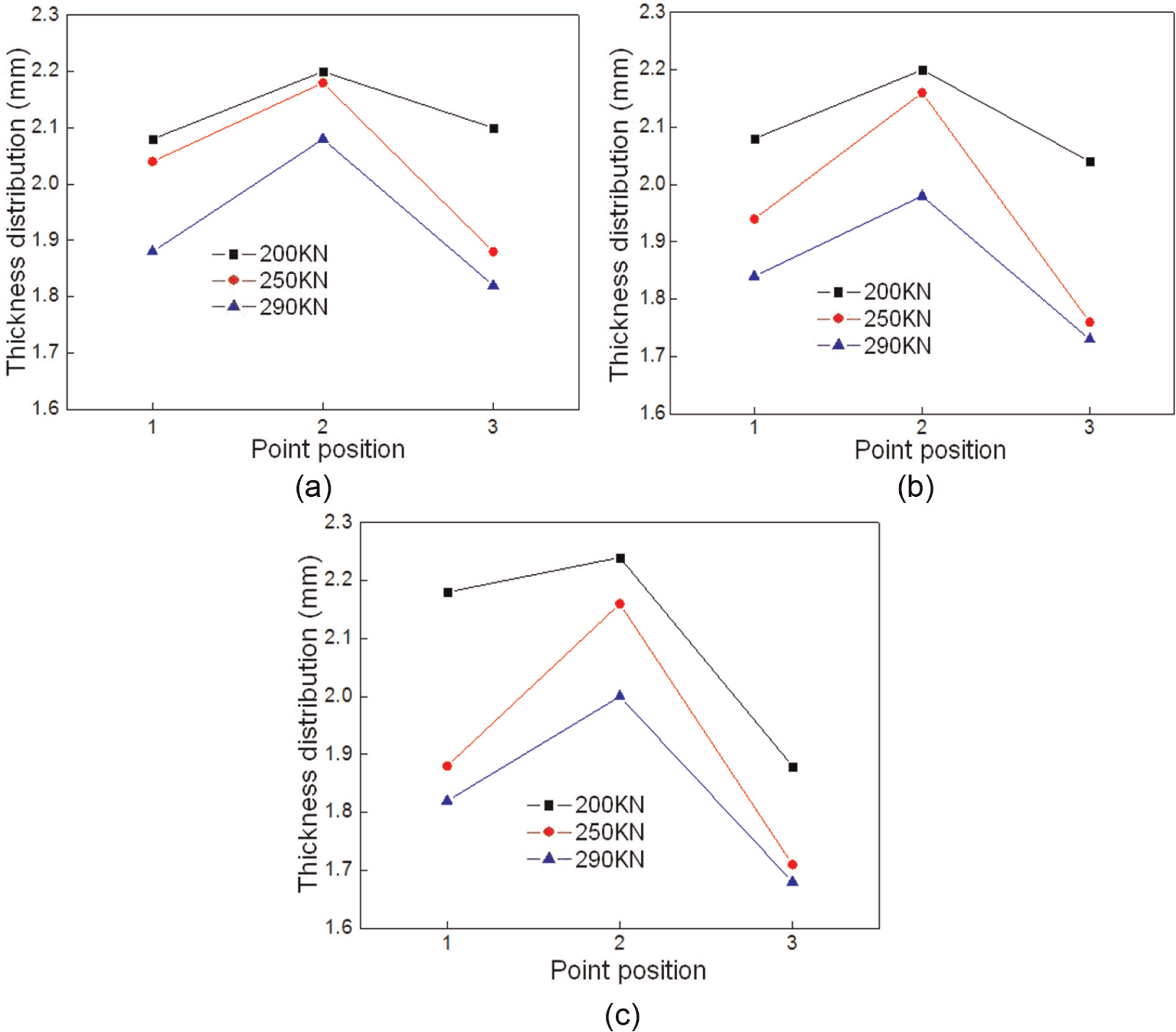
Effect of hole type on joining thickness: (a) round, (b) square and (c) hexagonal.
It can be seen from Figure 9 that all the thicknesses of the joint with different hole types tend to decrease with increasing load. The thickness distribution of the round hole scheme is shown in Figure 9(a). When the load pressure is 200 kN, the thinning rates of point 1, 2 and 3 are 9.5%, 4% and 8.7%, respectively; when the load pressure is 250 kN, the thinning rates at corresponding points will increase to 18.3%, 9.5% and 20.9%, respectively. The thickness distributions of the square and the hexagonal hole scheme are shown in Figure 9(b) and (c), and the tendency of the joint thicknesses is almost the same as the former. By comparison, when the load pressure reaches 290 kN, the maximum thinning rates of the square and the hexagonal schemes, which are located at point 3 reaches 24.8% and 25.6%, respectively.
From the comparison, irrespective of hole types and different loading conditions, the joint thicknesses of point 2 are higher than other regions. Because point 2 is in the center portion and restricted by two sides, the thinning rate is relatively small. However, points 1 and 3 are restricted by one side, and the thickness thinning rates of points 1 and 3 are higher than point 2 under the same load conditions.
Conclusion
Embedded cold-pressing joining can achieve the joining of dissimilar sheets of different thicknesses, even the joining of multi-layer sheets. The carrying capacity of the joint regions is improved because of the interlocking of the convex teeth. Besides, the processed shape and number of holes have a significant impact on the quality of the joining.
The simulation results show that the sheets with lower strength undergo plastic deformation first under the same load conditions. The width of the joint portion increased with the increase in the amount of reduction of the punch; the width increment of aluminum sheet is much larger than that of the stainless steel sheet. Hole type has greater impact on stainless steel width increments and joint load, among them, the impact of the hexagonal hole is the most obvious.
Research on the shape characteristics of the joint showed that compared with the round and the hexagonal hole schemes, the stuffing of square scheme is relatively difficult because of the resistance around the corners. When the technology is unreasonable, “fake joining,” “unbalanced-partial load” and “hole deformation” defects occurred.
During the loading process, the stainless steel sheets are pressed and the aluminum sheets are embedded into the holes, only then the joining is obtained. The thinning rates of the sheets increases with the increase in pressure, but the thinning amount at point 2 is much less than that at points 1 and 3.
Footnotes
Declaration of conflicting interests
The authors declare that there is no conflict of interest.
Funding
This study was funded by Program for New Century Excellent Talents In Heilongjiang Provincial University (No.1253-NCET-008) and Natural Science Foundation of Heilongjiang Province of China (No. E201128) and the Foundation of Heilongjiang Educational Committee (No. 12520140).