
Abstract
Nickel-based alloys are widely used in applications requiring high strength at elevated temperatures such as in aircraft jet engines. However, nickel-based alloys such as Inconel 100 are still considered difficult-to-machine metal alloys. In this study, specially designed orthogonal cutting tests on Inconel 100 nickel-based alloy have been conducted using WC/Co cutting tool with two varying rake angles, cutting edge radii and at wide ranges of cutting speed and feed. Effects of those parameters on specific forces have been investigated. Serrated and segmented chip formation is observed and the mechanics of segmented chip have been modeled and validated using the experimental test data. Chip microscopic images are utilized in measuring and calculating chip formation angles, shear strain, and shear strain rate in the main shear zone and within the shear bands. It was found that segmentation is highly influenced by machining conditions, and energy distributions calculated with regard to machining parameters reveal that friction dissipation and material separation are significant in machining of Inconel 100 nickel-based alloy.
Introduction
Nickel-based alloys are often used in applications requiring superior strength in high temperatures and exist mainly as in Ni-Co-Cr, Ni-Fe-Cr, or Ni-Co-Fe alloying forms. In general, these alloys can withstand high temperatures without losing their strength. Therefore, they are a good choice for applications requiring high strength at very high temperatures such as hot sections of aircraft and gas engines. They often can be obtained via certain manufacturing routes such as forging, casting, or powder compaction followed by sintering. Particularly, Inconel 100 (IN-100) nickel-based alloy can be obtained through casting or sintering. In all these cases, the parts must be processed via finish material removal processes. However, machinability of these alloys is considered highly difficult1–3 due to their abundant fracture toughness and strain hardening behavior.4–6 Workpiece subsurface forms a hardened layer due to machining-induced thermal–mechanical loading. 7 Furthermore, heat generated during machining cannot be rapidly dissipated due to low thermal conductivity and this leads to excessive tool wear.8,9 At high temperatures, nickel-based alloy tends to adhere to the cutting tool edge and alloying related hard particles act as abrasives creating further complications of excessive wear.3,9–11 In the literature, extensive number of research studies has been reported addressing the issues related to machining nickel-based alloys.
In order to improve machinability and tool life, tool materials such as uncoated and coated carbides and ceramics have been widely used.1–16 It was found that tool edge radius is more critical since the cutting edge geometry cannot be perfectly sharp and must have a finite edge radius in these tool materials with high hardness but relatively low toughness. Then, tool edge induces large strains on the workpiece during cutting; hence, a hard layer forms on the subsurface resulting from plowing. While a positive rake tool geometry decreases plowing by shearing away the chip from workpiece efficiently and minimizes not only build-up on the cutting edge but also work hardening layer formation on the workpiece.
For rouging operations, a large edge radius is recommended to increase the strength of the cutting edge and reduce chipping. Since a larger edge radius tool induces larger strains and greater subsurface damage, work hardened layer would be thicker on the machined surface. The thickness of the work hardened layer is usually 0.05–0.075 mm and can be as large as 0.125 mm. Hence, a depth of cut deeper than the thickness of the work hardened layer must be taken in sequential cuts. In both semi-finishing and finishing operations, a positive rake cutting edge is recommended.
In addition, tool edge geometry and rake angle are found to be highly influential where especially tool edge geometry affects material adhesion and surface finish in machining of nickel-based super alloys. 15 In general, very small edge radius insert edges are preferred to minimize material adhesion and improve surface finish during machining. However, the effect of tool edge geometry and rake angle to a fuller extent still yet to be revealed on specific cutting, material separation, and friction energies with resultant fracture toughness of nickel-based alloys for process planning purposes.
In machining Inconel 718 (IN-718), high degrees of the work hardening with a rich layer of plastic deformation have been observed. 15 Material hardening behavior is claimed to be affected by the size of the grains, which was changing mainly due to dynamic recovery, refinement, and precipitation. 17 In machining of UDIMET 720, it was observed that the microhardness of the material was decreasing from the surface into the depth direction significantly within the cutting-affected layer. 14
In machining powder compaction sintered nickel-based alloy RR_X (which is considered similar to Inconel), it was observed that the processed chips adhere and redeposit on the machined surfaces during rough and finish turning. 12 However, changing depth of cut values in each turning pass has been seen effective in minimizing the occurrence of redeposition.
Characteristically, most nickel-based alloys include some content of carbide particles as gamma prime phase (γ′) in their structure. Carbide cutting tool materials include tungsten carbide grains in cobalt matrix. During finish machining, these carbide particles irregularly dislodge from the workpiece or tool structure and deposit onto the workpiece surface causing sudden rise in shear stress and leading to serious surface defects at the locations where product’s fatigue performance decreases substantially.18,19,20 The degree of carbide cracking also depends on the tool edge radius and cutting conditions especially depth of cut since at low feeds and depth of cuts, machining process is more sensitive to carbide particles that are typically in the size of 20 µm.
Consequently, there is a need for additional experimental studies and analyses to fully understand the influence of tool geometry and edge radius in machining of nickel-based alloys. Therefore, experimental investigations and related analyses are carried out in this study to understand the effects of machining parameters such as cutting speed and feed and tool geometry such as rake angle and edge radius on process mechanics, namely, segmented chip formation, specific energies for shearing, friction and material separation, and friction coefficient between carbide tool and the workpiece in machining of Inconel 100 (IN-100 nickel-based super alloy.
Experimental study
Orthogonal turning of webs (3 mm thick) has been performed using uncoated tungsten carbide (WC) cutting tools in a rigid CNC turning center (ROMI Centur 35E) at Manufacturing & Automation Research Laboratory of Rutgers University. Test workpiece is machined with plunge turning. This experimental setup has created the orthogonal cutting condition, as illustrated in Figure 1. On nickel-based alloy disks, grooves (19 mm deep and 3 mm wide) are machined at a cutting speed (vc) of 18 m/min and a feed (h) of 0.06 mm/rev to create the test workpiece with multiple webs. The cutting forces were measured with a Kistler turret-type three-component force dynamometer (Type 9121, Kistler Instruments AG, Switzerland) and high-speed data acquisition devices. The signal generated at each component at the force dynamometer was amplified using charge amplifiers (Kistler Type 5814B1, Kistler Instruments AG, Switzerland). The amplified signal is acquired and sampled (a sampling frequency of 1000 Hz per channel) using a laptop computer-based data acquisition system (PCMCIA card and Type 2825A-02-1; Kistler DynoWare software).
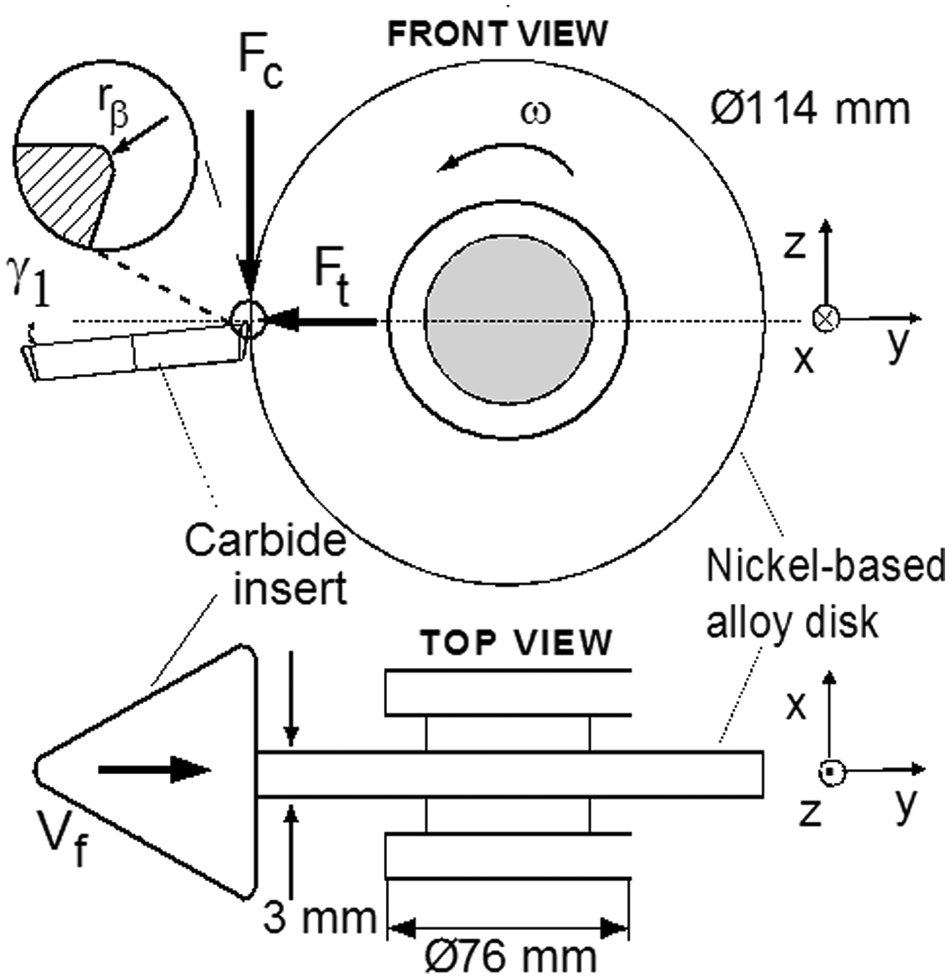
Orthogonal cutting of a nickel-based super alloy workpiece specimens.
The experiments have been conducted using uncoated carbide tools with two different edge radiuses (rβ = 10 and 25 µm) and tool holders with 0° and +3° rake angles (γ1) at four different cutting speeds (vc = 6, 12, 18, and 24 m/min) and six different feeds or uncut chip thicknesses (h = 0.01, 0.025, 0.05, 0.075, 0.1, and 0.125 mm/rev).
Analysis of chip morphology
The influence of serrated chip formation on machining process outputs—cutting forces, temperature and surface roughness and integrity—is profound. Therefore, a thorough understanding of mechanics of serrated chip formation in nickel-based super alloy machining is considered important.
Fundamental mechanism of serrated chip formation in titanium alloys (e.g. Ti-6Al-4V) and nickel-based alloys (e.g. IN-718) has been long debated. According to one theory, 3 this is due to the thermal softening (i.e. localized shearing). Another theory claims that there exists a crack initiation in the primary shearing zone (i.e. a narrow band between the tool tip and the chip free surface), which causes serration in the chips.4–7
Both theories are supported by experimental evidences, and the common belief is that both mechanisms are in effect. At low cutting speeds, a crack-initiated serration occurs, and at high cutting speeds, localized shearing-based serration occurs due to higher temperatures and it becomes more dominant.
In the orthogonal cutting of nickel-based super alloy IN-100, morphology of the chip formation has been investigated. Chip images captured using field emission scanning electron microscopy (FESEM) depict highly serrated shape with regions of high plastic deformations (adiabatic shear bands) and cracks mixed, as shown in Figure 2. It should be noted that views of segmented chips were accurate enough to reveal the chip segmentation dimensions and in close-up examination lamellar shear zones.
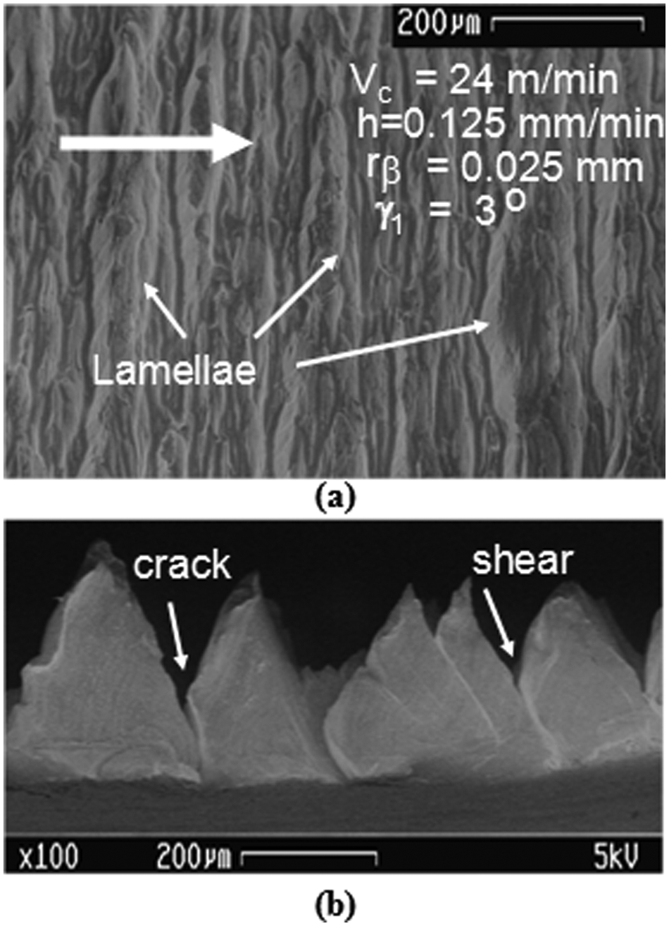
Morphology of the continuous but segmented chips: (a) lamellae on the free surface of the chip and (b) cross-sectional image of the same chip with shear and crack formation.
It is believed that adiabatic shear band is a form of failure mechanism that occurs in both titanium and nickel-based super alloys when they are deformed at a high rate in machining processes. Adiabatic shear bands are usually very narrow, typically 5–50 µm, and they consist of very highly sheared material. It should be noted that “adiabatic” is a thermodynamic term meaning an absence of heat transfer—the heat produced is retained in the zone where it is created. Furthermore, adiabatic shear bands are commonly the precursors to fracture.
The presence of adiabatic shear bands in serrated chips does not rule out the existence of segmented chip formation with crack initiation. Many experimental observations of chip morphology indicated that both cracks and adiabatic shear bands can coexist.21–26
In general, continuous but serrated chip formation has been observed with the cutting conditions specified in this study (see Figure 3). At lower feeds, continuous chips with little or no serration were seen. Segmentation increased at higher feeds and cutting speeds similar to other observations reported for titanium and nickel-based alloys in the literature.16,25,27 Segmentation has been more dominantly affected by the increase in feed or uncut chip thickness increase.

FESEM images of segmented chip formation.
Chip FESEM images revealed brighter coloration occurred at higher cutting speeds indicating temperature rise–related material microstructure alteration. This alternation may be an indication in change in crystalline structure due to the cutting-related temperature rise that can reach above dynamic recrystallization of nickel-based alloy. During the machining operation, the workpiece material is exposed to a thermal, mechanical, and chemical energy that can lead to strain aging and recrystallization of the material.21,22,24 Due to the strain aging process, the material might become harder but less ductile, and recrystallization might cause the material to become less hard but more ductile. It is believed that these microstructural alterations can lead to white layer formation when strain aging is dominant, and when recrystallization is also observed.23,24,26
Mechanics of serrated chip formation
Many researchers investigated the mechanics and dynamics of chip formation when machining heat resistant alloys such as titanium and nickel-based alloys.21–23,25 Most recently, Cotterell and Byrne 27 have investigated the dynamics of chip formation and the relation between cutting parameters and chip serration in Ti-6Al-4V alloy. Pawade et al. 16 investigated the specific shear energy of the workpiece material in machining IN-718 using an elastic–viscoplastic analytical model they created and found out that shear band spacing increases with increasing feed. Fang et al. 28 provided a segmented chip formation model and investigated chip formation mechanics in machining of aluminum alloys. In this study, we utilized a segmented chip formation model that is similar to models presented by Cotterell and Byrne, 27 Pawade et al., 16 and Fang et al. 28
In this model, the serration of the chip creates a sawtooth shape, and the pitch of these chips (pch) and the shear band thickness (δsb) parameters become important factors in determining the shear strain at the adiabatic shear band. Also, the chip morphology will have peaks and valleys, which makes the measurement of the chip thickness more difficult. Instead, the minimum chip thickness of a sample and a maximum chip thickness are measured, and the arithmetic average of these two is accepted to be the experimental chip thickness. According to this model, average shear strain calculation can be done as follows. 27
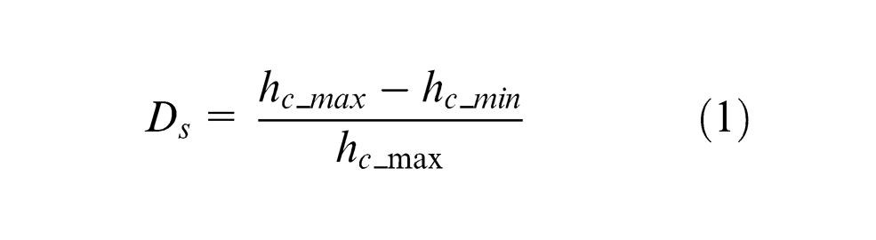
An important measure of chip formation mechanism in nickel-based alloy machining, which is related to adiabatic shearing and crack formation, is the degree of segmentation. It also indicates the severity of chip segmentation. The degree of segmentation (Ds) is formulated using the minimum (hc_min) and maximum (hc_max) experimental chip thicknesses along the serrated chips where their locations are indicated in Figure 4 28
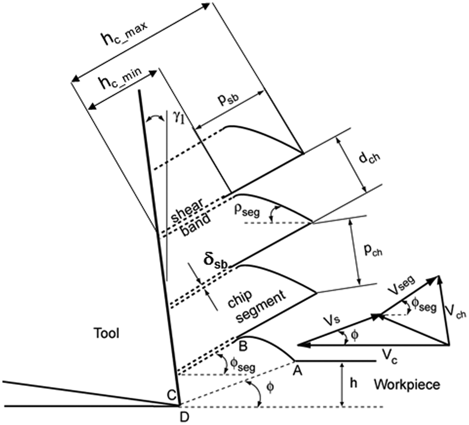
Serrated chip formation model and its hodograph.
The chip ratio (rc) is defined by the ratio of undeformed chip thickness (h) (or feed in orthogonal cutting) to the average thickness of the segmented chips (hc) that are measured experimentally

Hence, the shear angle can be found utilizing the measured chip ratios using the following formula, which is derived from the ratio (rc) of undeformed chip thickness (h) to the average chip thickness (hc) and rake angle (γ1)

Following this formulation, the shear strain in the primary shear zone (γ) can be found and the calculation based on continuous chip formation assumption becomes

In addition, average shear strain in segmented chip (γseg), average shear strain in the shear bands (γsb), and average strain rate based on segmented chip calculations become as suggested in Cotterell and Byrne 27
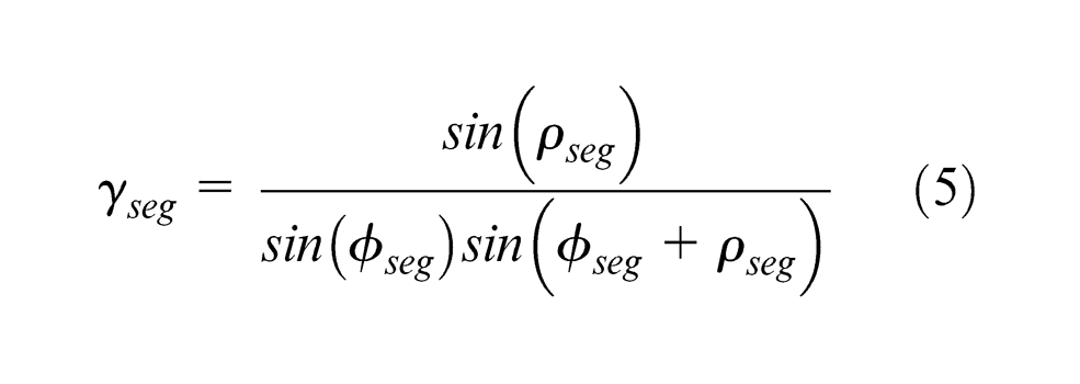

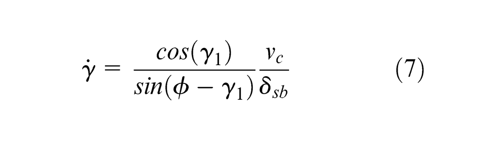
where ρseg is chip segment angle, φseg is shear angle at the chip segment, psb is depth of segmentation, and δsb is shear band thickness. Then, using FESEM images and measurements on chip morphology (see Figure 5), average strain and strain rate can be found (Table 1).
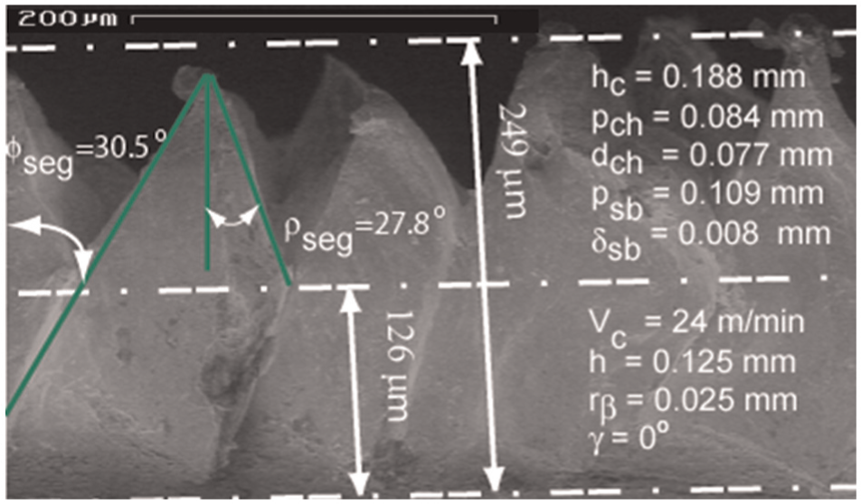
An example for the chip morphology measurements.
Influence of machining and tool geometry parameters on calculated strain and strain rates.
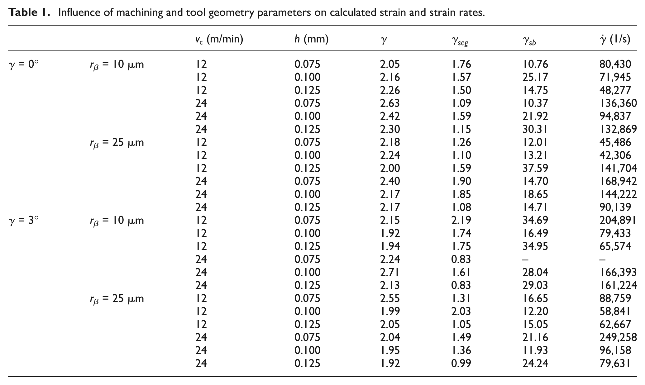
It should be noted that severe shearing (between 10 and 30 mm/mm) occurs within the shear bands. This severity of deformations can also be seen as potential for fracture strain–initiated crack formation and indicates possible crack initiation on the machined surface.
Effects of machining conditions on degree of segmentation
The overall effects of machining conditions on degree of segmentation are shown in Figure 6. It is observed that increasing feed (h) or cutting speed (vc) does not have a significant effect on the degree of segmentation (Ds) (<5%), whereas increasing cutting edge radius (rβ) (∼5%) and decreasing rake angle (γ1) (∼10%) decrease the degree of segmentation.
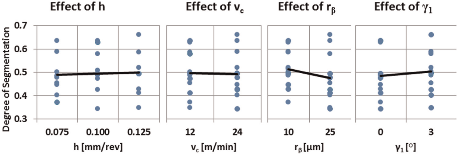
Effects of feed (h), cutting speed (vc), edge radius (rβ), and rake angle (γ1) on the degree of segmentation.
Effects of machining conditions on main shear angle
The effects of machining conditions on the main shear angle (φ) are given in Figure 7. While all the parameters had notable effects on the main shear angle, it can be observed that with increasing feed (h) and decreasing cutting speed (vc), the shear angle increased significantly (∼20%). With increasing cutting edge radius (rβ) and rake angle (γ1), a less significant increase (∼10%) in the shear angle was also observed.
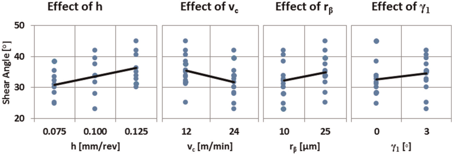
Effects of feed (h), cutting speed (vc), edge radius (rβ), and rake angle (γ1) on shear angle.
Effects of machining conditions on segmented shear angle
The effects of machining conditions on segmented shear angle, φseg (see Figure 4), are given in Figure 8. While changing cutting edge radius (rβ) and rake angle (γ1) did not have significant effects (<5%), it was observed that with increasing feed (h) and cutting speed (vc), the segmented shear angle increased by 10%−20%.
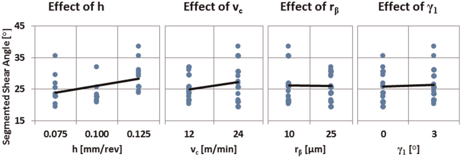
Effects of feed (h), cutting speed (vc), edge radius (rβ), and rake angle (γ1) on segmented shear angle.
Effects of machining conditions on chip segment angle
The effects of machining conditions on chip segment angle (ρseg, see Figure 4) are given in Figure 9. With increasing cutting speed (vc), a ∼25% decrease in the chip segment angle was observed. In addition, increasing feed (h) increased the chip segment angle by ∼7%. The other parameters did not have significant effects on the chip segment angle (<5%).
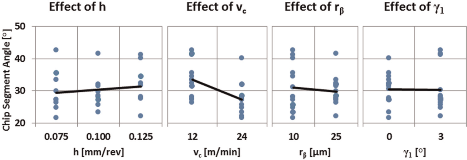
Effects of feed (h), cutting speed (vc), edge radius (rβ), and rake angle (γ1) on chip segment angle.
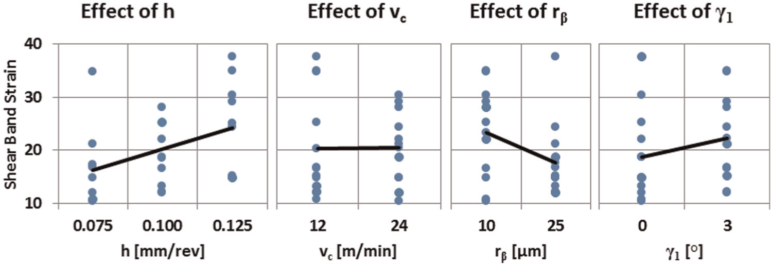
Effects of machining conditions on shear strain in shear band
The shear strain in the shear band (γsb, see Figure 4) has been found to be in the range of 10–40, indicating a very rapid secondary shearing due to work material yielding and perhaps flow softening or dynamic recrystallization-related weakening. The effects of machining conditions on shear strain in shear band indicate an increase when feed (h) and rake angle (γ1) are increased (∼46% and ∼32%), and cutting edge radius (rβ) is decreased (∼16%), as shown in Figure 10. Cutting speed (vc) did not have an observable effect on the shear strain in shear band (<1%).
Effects of feed (h), cutting speed (vc), edge radius (rβ), and rake angle (γ1) on shear strain in shear band.
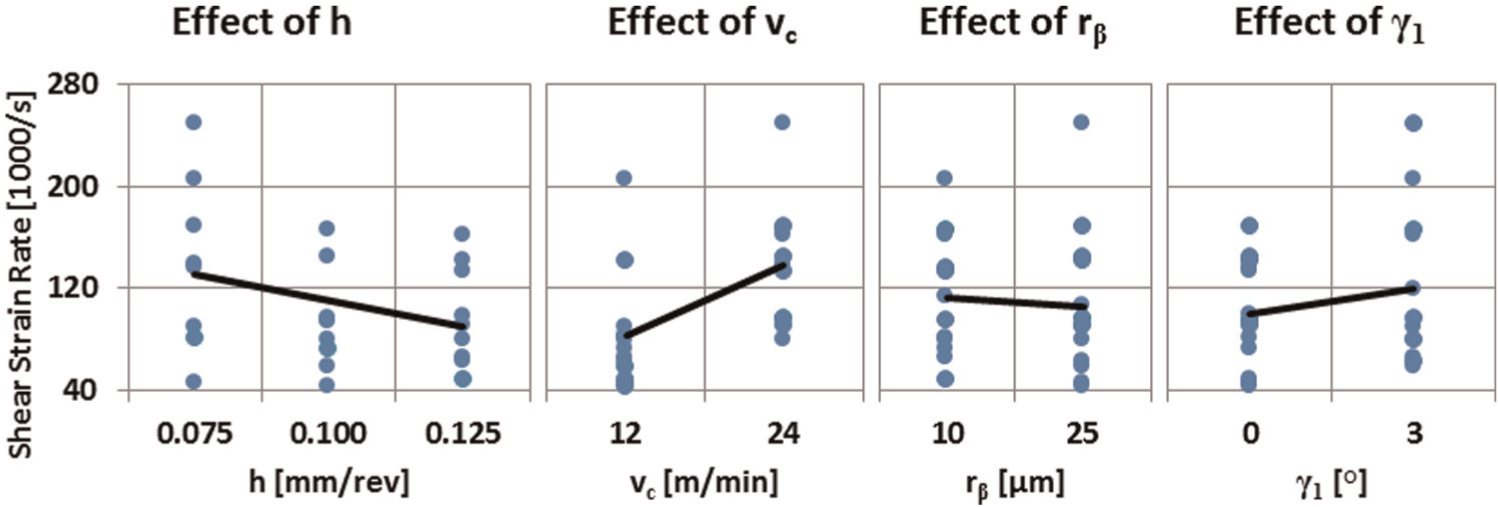
Effects of machining conditions on shear strain rate
As well known, increased cutting speed increases the shear strain rate in the cutting zone. The results shown in Figure 11 agree with this common knowledge, indicating a ∼40% increase in shear strain rate with increasing cutting speed (vc). The effects of other machining conditions such as edge radius (rβ), rake angle (γ1), and feed (h) on shear strain rate are also given in Figure 11. Increased feed (h) caused a decrease of ∼30% in shear strain rate. In addition, a neutral rake angle of (γ1 = 0°) resulted in lower shear strain rate (∼16%), and a smaller edge radius (rβ) resulted in higher shear strain rate (∼7%).
Effects of feed (h), cutting speed (vc), edge radius (rβ), and rake angle (γ1) on shear strain rate.
Specific cutting forces and energy distributions
As widely reported in the literature, machining nickel-based alloys often results in extremely high specific cutting forces. The highest forces are encountered at lower cutting speeds and feeds. The main reason for this observation is the increasing specific energy for shearing and the material separation as suggested by Atkins 29 and Subbiah and Melkote, 30 even though this approach has been criticized by some researchers.
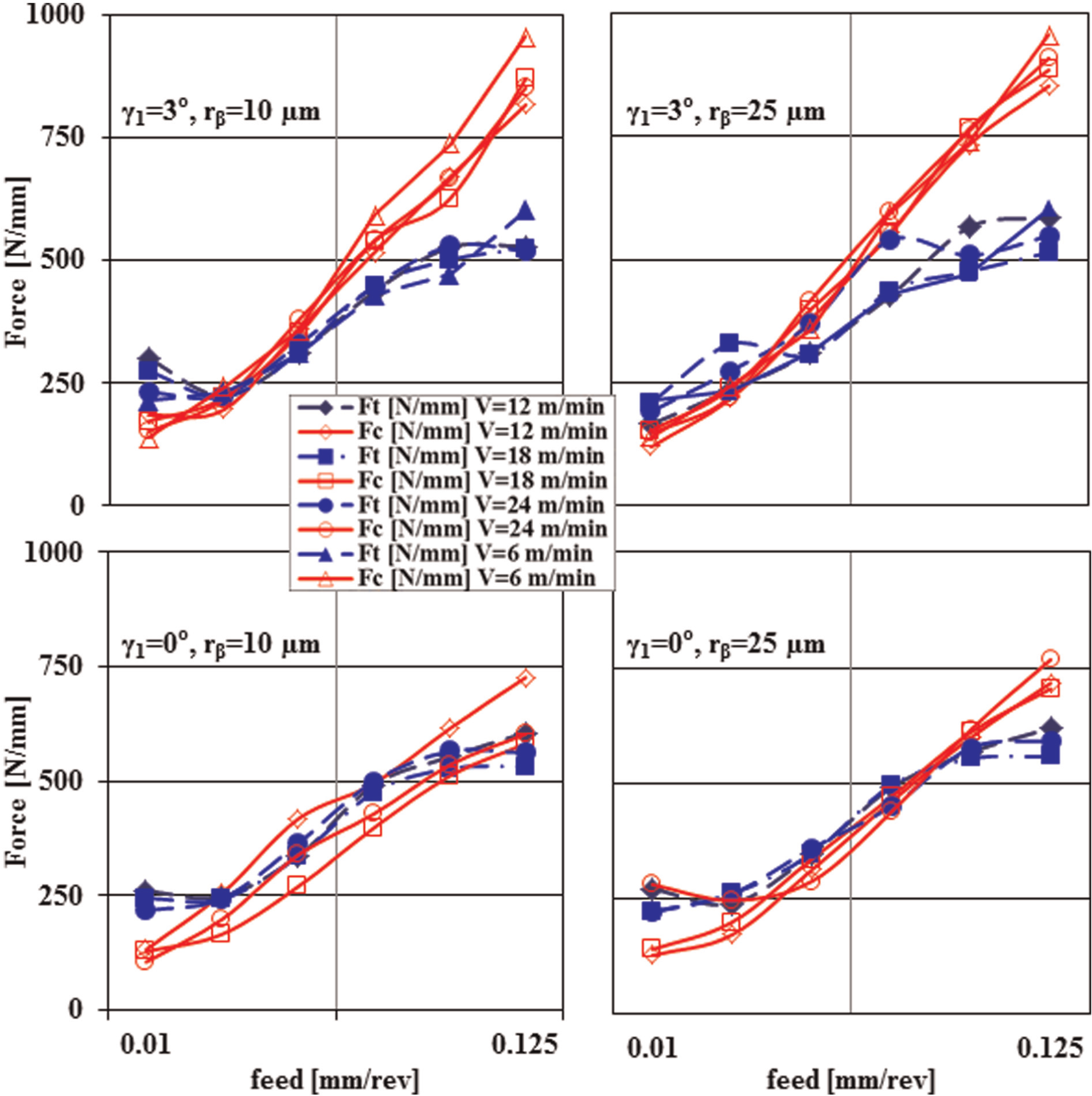
Therefore, in order to better understand the effects of tool edge radius, rake angle and cutting speed on machinability, specific forces and energies for shearing, friction, and material separation are investigated. Specific cutting forces measured in orthogonal cutting tests of nickel-based alloy disks have been presented in Figure 12. Positive rake angle and larger edge radius resulted in higher specific cutting forces. At higher cutting speeds, specific cutting force decreases due to thermal softening and strain softening at higher strain rates.
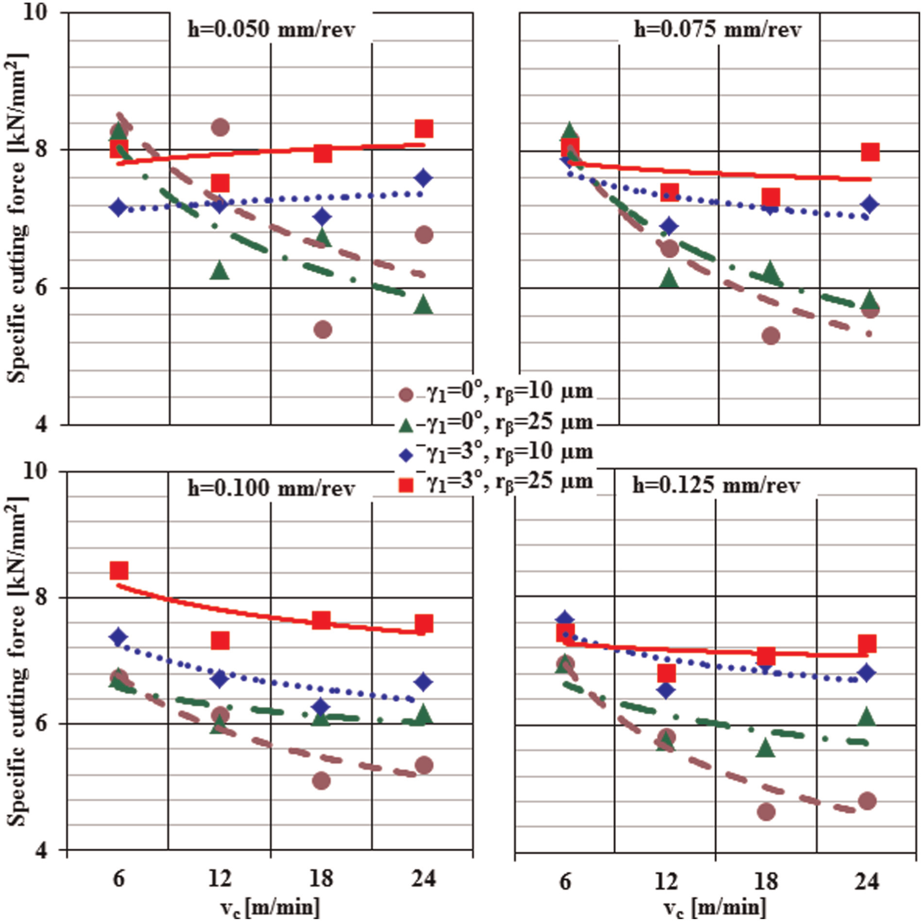
Measured specific cutting forces at lower and higher feeds (0.05–0.125 mm/rev).
In machining processes, the temperature increase during operation is mainly caused by three different energy sources: shear energy (plastic dissipation), frictional dissipation, and surface formation (material separation). The total cutting energy Fcvc is the sum of these three components, since the cutting force and velocity are the sources for these energy terms
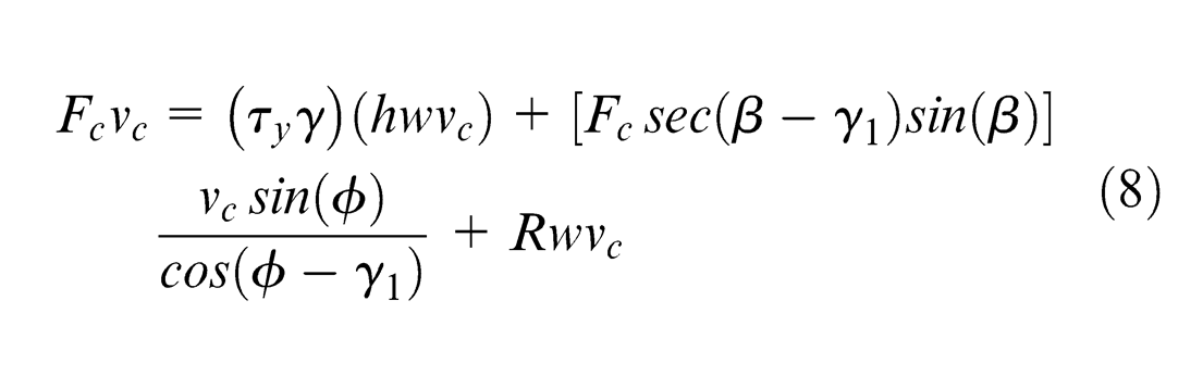
In this equation, Fc is the cutting force; vc is the cutting velocity; τy is the shear yield stress; γ is the shear strain; h is the uncut chip thickness; w is the width of cut; β, γ1, and φ are the friction, rake, and shear angles, respectively; and R is the fracture toughness of the material. 29 This equation can also be written as

Here, Q is a common denominator represented by
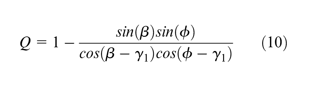
In order to find the fracture toughness (R) and the shear yield stress (τy) of the material, we follow a procedure suggested by Atkins 31 and also outlined in Subbiah and Melkote. 30 First, forces in thrust and cutting directions are measured. Then, the friction angle (β) is found using the following equation

From this equation, the shear angle is found as follows

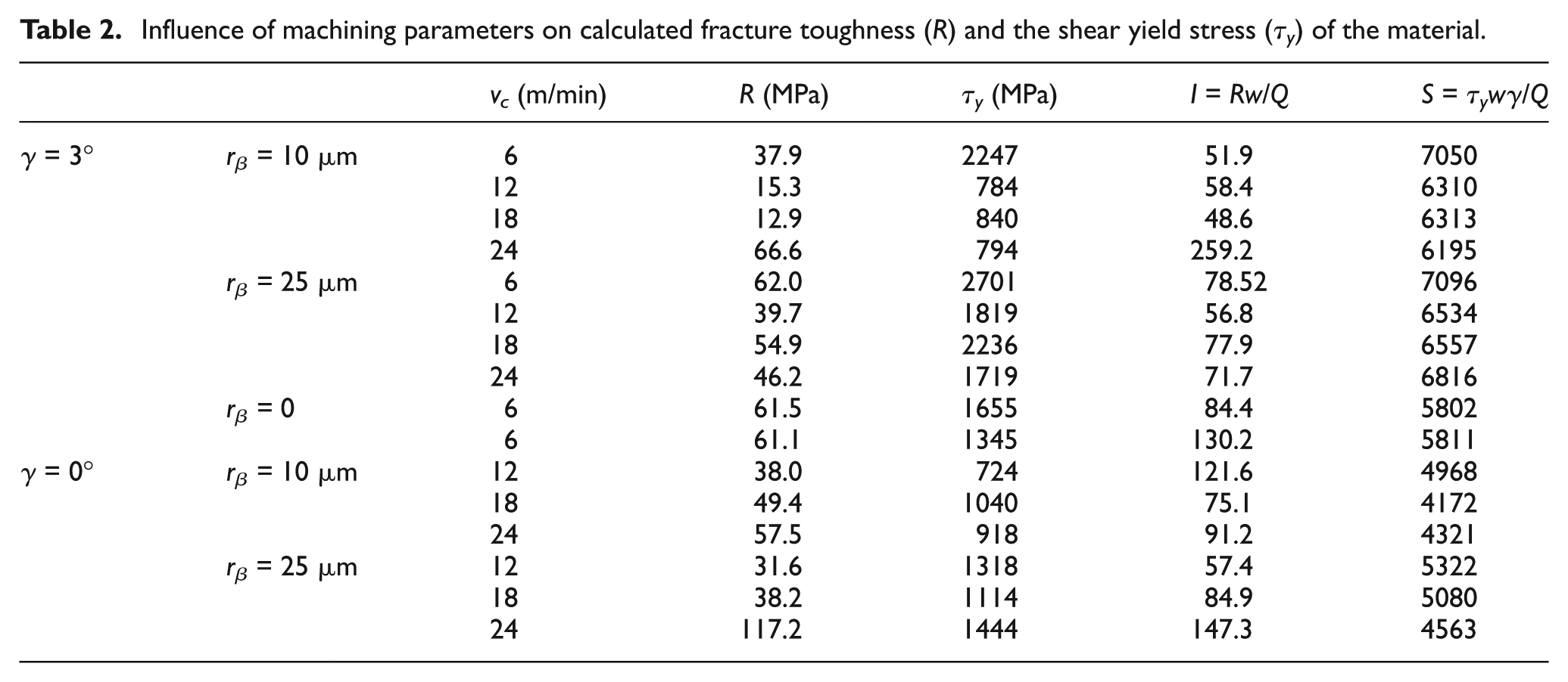
Then, various meaningful combinations of R and τy are created, and all of the combinations are subjected to calculation of I = Rw/Q and S = τywγ/Q, which are the intercepts and slopes of the force graphs. When the ratio of (I/S) calculated this way is equal to the ratio (I/S) calculated from the force measurements, the calculation is ended and fracture toughness (R) and shear yield stress (τy) of the material, as well as the shear angle (φ), are found (see Table 2). These values are then used in the energy distribution formula to find the specific energies distributed to different sources of energy. Calculated energy distributions for plastic dissipation (shearing), friction dissipation and surface formation energy using this formulation are given in Figure 13. It should be noted that increasing surface formation energy should result in higher fracture toughness as it has been confirmed with the results presented here.
Influence of machining parameters on calculated fracture toughness (R) and the shear yield stress (τy) of the material.
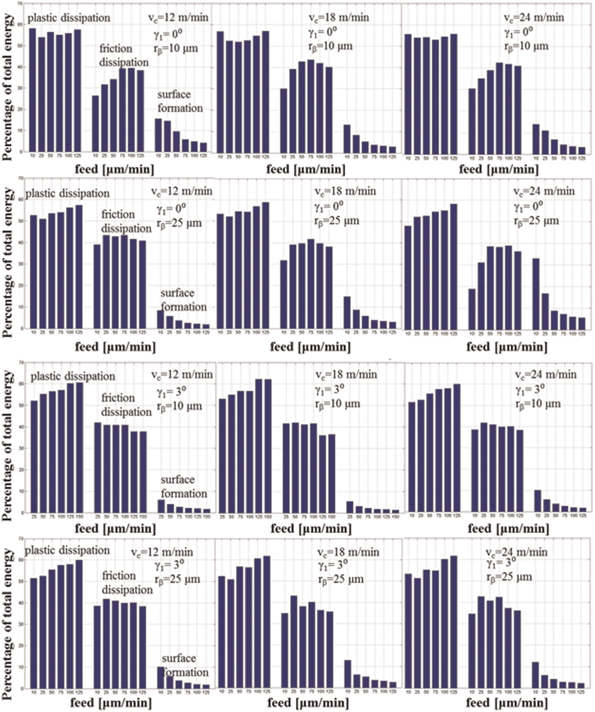
Calculated energy distributions for plastic dissipation (shearing), friction dissipation and surface formation energy.
Analysis of friction coefficient
In determining the friction coefficient under dry machining conditions of nickel-based alloy, measured cutting and thrust forces are utilized. Forces measured at two different rake angles and two different tool edge radii are shown in Figure 14. For zero rake angle cutting conditions, cutting forces and thrust forces increased linearly with the same slope between 0.025 and 0.1 mm/rev feed or uncut chip thickness. For a positive rake angle (γ1 = 3°), thrust forces were lower; hence, the slope for thrust force trends was seen smaller indicating lower friction coefficient in those cutting conditions. Due to a possible size effect, thrust forces become greater than cutting forces when the feed (h) or uncut chip thickness is smaller than the tool edge radius (rβ).
Experimentally measured cutting and thrust forces.
Friction coefficient is calculated using two distinct methods: (1) mean friction coefficient method and (2) gradient-based friction coefficient method. Since the friction coefficient is quasi-steady along the friction surface, a constant mean value of the ratio of measured frictional force to cutting force could be used, which can be determined by equation (13) for the mean friction coefficient method. In gradient-based friction coefficient determination, experimental friction identification proposed by Albrecht 32 and improved by Arrazola and Meslin 33 has been utilized. Experimentally measured cutting (Fc) and thrust (Ft) forces for increasing feeds from 0.01 to 0.125 mm/rev were plotted against each other. The slope of the curve was calculated where μ is the friction coefficient and γ1 is the rake angle. From the Fc–Ft plot, it is observed that the critical uncut chip thickness is higher than the cutting edge radius. The regions on the Fc–Ft plot can be correlated to the zones over the tool–chip contact area where high- to low-pressure contact areas exist. Equation (14) can be derived to find the coefficient of friction


Friction coefficients that are found using mean (average) friction coefficient method and gradient method have been compared with each other, as shown in Figure 15. The results indicated that average friction coefficient is higher when compared to friction coefficient obtained from gradient method. In addition, using gradient friction method, the effect of cutting speed on friction coefficient has been obtained, as shown in Figure 16.
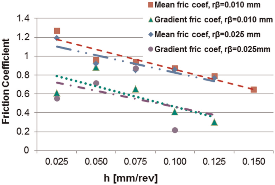
Comparison of friction coefficient obtained using mean friction coefficient method and gradient method for machining nickel-based alloy at vc = 12 m/min.
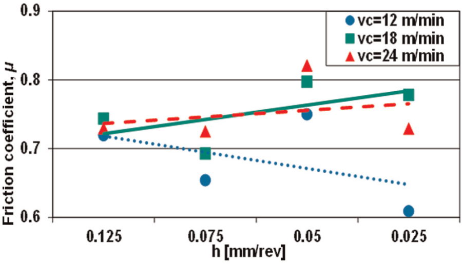
Friction coefficient identified using gradient method for γ1 = 3° and rβ = 10 µm.
Summary of the results and discussions
In orthogonal cutting tests, continuous but serrated chip formation is observed under the machining conditions considered in this study. At lower feeds, continuous chips with little or no serration were seen. Segmentation increased at higher feeds and cutting speeds similar to other observations reported in the literature.16,25,27,28 Segmentation has been more dominantly affected by an increase in feed or uncut chip thickness.
The overall effects of machining conditions on the degree of segmentation indicate that increasing feed (h) results in higher degree of segmentation (Ds) when a positive rake angle (γ1 = 3°) is used. Severe shearing (γsb = 10–30 mm/mm) occurs within the shear bands as a potential for fracture strain–initiated crack formation.
Measured specific cutting forces depict that positive rake angle and larger edge radius result in higher specific cutting forces. At higher cutting speeds, specific cutting force decreases due to thermal softening and strain softening at higher strain rates.
In machining nickel-based super alloy materials, work hardening behavior and the degree (or depth) of work hardening were reported mainly as signs of severe plastic deformation. The energy dissipated through plastic deformation work has been found between 50% and 60% of the total machining energy. As feed increased, energy dissipation through plastic work increased. Energy dissipation through friction has been found to be ∼40%, indicating a severe friction situation in machining of IN-100 nickel alloy. The energy spent for material separation and surface formation due to the fracture strength of the material has been found less than 10% of the total energy. But this component is substantially higher at low feeds (Figure 13).
Conclusion
In this study, mechanics of segmented chip formation and machinability of nickel-based super alloy IN-100, which is obtained from powder metallurgy and by sintering, are investigated using orthogonal cutting tests. A range of machining parameters has been considered, and orthogonal cutting tests on IN-100 disks have been conducted using uncoated WC/Co cutting tools with two different rake angles and edge radii. Cutting forces are measured and effects of machining parameters on specific cutting forces are reported. Chip images are utilized in measuring and calculating chip formation angles, shear strain, and shear strain rate in the main shear zone and within the shear bands. Energy distributions calculated with regard to machining parameters reveal that friction dissipation and material separation are significant in machining of IN-100 nickel-based alloy. Furthermore, fracture toughness and shear yield stress have been calculated in each condition. It was found that material separation energy and fracture toughness of IN-100 material increase with decreasing cutting speed and feed but with increasing edge radius. These results also reveal some important aspects of nickel-based alloy machining, which may be useful for further investigations and modeling studies. Some specific conclusions on effects of machining parameters can be given as follows:
Measured specific forces reveal that at higher cutting speeds, specific cutting force decreases due to thermal softening and material flow softening behavior at higher strain rates. Positive rake angle and larger edge radius resulted in higher specific cutting forces.
Main shear angle is increased ∼20% by increasing feed and increasing tool edge radius. While increasing cutting speed decreases the main shear angle more than 10%, increasing rake angle and edge radius decreases the main shear angle by ∼10%.
Main shear strain rate is largely affected by feed and cutting speed as expected.
Segmented chip properties are also affected by machining conditions.
Degree of segmentation is mainly affected by tool edge radius (decreases with increasing edge radius) and slightly affected by tool rake angle (increases with increasing rake angle).
Shear strain in shear bands, which is a major indicator for secondary (or adiabatic) shearing, is affected by increasing feed and rake angle. However, increasing tool edge radius decreases shear band strain by about ∼35%.
Chip segment angle is also affected mainly by cutting speed (>20% decrease for 100% increase in cutting speed).
Segmented shear angle increases with increasing feed and cutting speed by about ∼10%−20%.
Footnotes
Nomenclature
dch chip segment length [mm]
Ds degree of segmentation [-]
Fc cutting force
Ft thrust force
h feed or uncut chip thickness [mm/min]
hc average thickness of the segmented chips [mm]
hc_max maximum thicknesses of the segmented chips [mm]
hc_min minimum thicknesses of the segmented chips [mm]
pch pitch of the chip segments [mm]
psb depth of segmentation [mm]
R fracture toughness [MPa]
rc chip ratio [-]
rβ edge radius [µm]
vc cutting speed [m/min]
Vch chip velocity [mm/min]
Vf feed velocity (rate) [m/min]
Vs shearing velocity [mm/min]
Vseg velocity of the chip segmentation [mm/min]
w width of cut [mm]
β friction angle [degree]
γ shear strain in the primary shear zone [mm/mm]
γsb average shear strain in the shear bands [mm/mm]
γseg average shear strain in segmented chip [mm/mm]
γ1 rake angle [degree]
δsb shear band thickness [mm]
µ friction coefficient [-]
ϕ shear angle [degree]
ϕseg segmented shear angle [degree]
ρseg chip segment angle [degree]
τy shear yield stress [MPa]
τy shear yield stress [MPa]
Acknowledgements
The authors acknowledge the assistance from Mr Michael Pandolfo and Mr Adam Miller during the experimental study and Mr Joshua Greenhaus for data analysis.
Declaration of conflicting interests
The authors declare that there is no conflict of interest.
Funding
This research was conducted through a contract agreement with United Technologies Research Center and partially supported by NSF grants CMMI-0758220 and CMMI-1130780.