
Abstract
Numerical and experimental investigations on micro-detonation of striking arc machining of alumina ceramics were performed to ascertain the material removal mechanism and study the effects of the process parameters on the machining performance. The shape of the micro-detonation plasma jet and the ablation pit generation process were observed by high-speed video and machining test. A three-dimensional finite element model for temperature simulation during a single-pulse micro-detonation of striking arc machining process was developed and validated by corresponding experiments. The effects of the five process parameters, that is, working current, gas pressure, pulse width, nozzle stand-off distance, and muzzle diameter, on the highest temperature and material removal rate were studied by employing the Taguchi method. The findings indicated that the simulated results were in good agreement with the experiments. The material removal mechanism for alumina machined by micro-detonation of striking arc machining was determined based on high-speed video observation, numerical simulation, and experimental study. The alumina ceramics were mainly removed by a combination of sublimation, melting, and phase transformation under the synergistic effect of high temperature and high impact force of the micro-detonation plasma jet. The highest temperature and the material removal rate were significantly affected by the process parameters. Both temperature and material removal rate increased with increase in the working current, gas pressure, and pulse width, but decreased with the increase in the nozzle stand-off distance and nozzle diameter. Based on the analysis of variance and the effects of parameters on the highest temperature and material removal rate, the optimal combination of parameters was presented. This study may serve as a reference in understanding the machining mechanism of micro-detonation of striking arc machining and presents a method that can be used for efficient machining of alumina.
Keywords
Introduction
Alumina (aluminum oxide, Al2O3) is one of the most common structural ceramics applied in machine tool inserts, heat-resistant packing, electrical and electronic components, and attachments to melting ducts and refractory linings because of its desirable properties, such as low chemical stability, superior wear resistance, high hardness, low electrical conductivity, low thermal conductivity, and low density. Unfortunately, its inherent characteristics, such as hardness, brittleness, and low fracture toughness, make alumina machining difficult at high precision involving complex shapes. 1 Although the conventional ceramic machining technique that uses diamond grinding remains the most desirable and reliable technique for alumina machining, it is inefficient and costly. Shen et al. 2 claimed that the grinding cost accounts for 80% or more of the total component cost. Samant and Dahotre 3 believed that grinding accounts for 60%–90% of the cost. Furthermore, Barnes et al. 4 found that grinding often generates products with surface and subsurface cracks, certain amounts of plastic deformation, pulverization layers, and significant surface residual stresses. Therefore, the development of nontraditional processing techniques that can fabricate alumina parts at a relativity high rate is crucial.
Alumina is a typical insulating brittle material, so it is difficult to be machined by cutting and conventional electrical discharge machining process. Alumina has been successfully fabricated by many thermal machining technologies. Yan et al. 5 machined a deep crack-free cavity underwater with CO2 laser and obtained a set of optimized parameters for laser milling process. Yan et al. 6 also performed laser crack-free cutting of thick-sectioned alumina. Chang and Kuo 7 applied laser-assisted machining on alumina and obtained a much better surface roughness than that acquired through conventional machining. Liu et al. 8 machined alumina by electrical discharge milling with the assisting electrode of a thin copper sheet. Tian et al. 9 developed a novel, nonconventional machining technology called micro-detonation of striking arc machining (MDSAM), which was proven to be an alternative technique for brittle and hard materials. Zhang et al. 10 found that MDSAM possesses better attributes, such as lower original equipment cost, decreased operation cost, reduced power per volume, higher material removal rate (MRR), and more flexible process compared with conventional machining processes. MDSAM can be used for drilling, milling, turning, and grooving when combined with a positioning system.
During the MDSAM process, the machining energy is transferred by plasma jet. When the plasma jet bursts out from the nozzle of the micro-detonation generator, the jet is immediately applied to the workpiece until the pulse vanishes. The machining process is shown in Figure 1. Observing the clear shape of the plasma jet and the machining process is very difficult because the machining time is short and the machining process generates intensive light and heat. Currently, the suitable technology used to observe the high-speed transient process is high-speed video technology. High-speed video is widely used in the thermal machining process. Harwig et al. 11 used high-speed video to analyze the droplet melting phenomena and evaluate the arc behavior in the variable polarity gas metal arc welding process. Aeschliman et al. 12 observed the inductively coupled plasma by high-speed video during the laser ablation of Y2O3 pellet. Therefore, high-speed video was employed in this study to observe the transient machining process and the shape of the micro-detonation plasma jet.
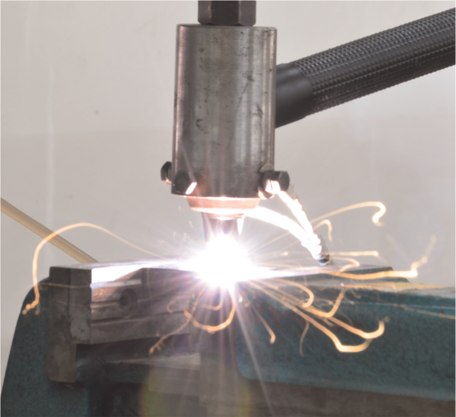
Photograph of the MDSAM process.
In this study, alumina machining by MDSAM was conducted. Numerical simulations were performed to study the effects of five major process parameters on temperature fields and MRR. The three-dimensional (3D) finite element (FE) modeling of single-pulse machining was developed and then validated by corresponding experiments. High-speed video and scanning electron microscopy (SEM) of the machined pit were employed to investigate the machining characteristics. The material removal mechanisms of alumina during MDSAM were revealed based on the numerical and experimental results.
Experimental procedure
Experimental setup and material properties
The experimental setup is illustrated in Figure 2. The MDSAM setup consisted of special pulse power supply, pulse controller, micro-detonation generator, gas supply, 3D numerical control table, and high-speed video setup. The maximal output power supplied by the special pulse power was 15 kW. The working current was adjustable, which ranged from 20 to 100 A. The nozzle of the micro-detonation generator was connected to the positive terminal of the special pulse power and served as an anode, whereas the hafnium cathode was connected to the negative terminal. The pulse controller was used to control the pulse width and pulse interval. The pulse width was about 60–120 ms, whereas the pulse interval was about 600–1000 ms. The pulse interval was about 10 times greater than the pulse width to ensure that the processing region could be sufficiently cooled by the cooling gas flow. In this study, the compressed air served as the working and cooling gas, as provided by the gas supply. The high-speed video setup consisted of a digital high-speed color video camera (PHOTRON FASTCAM Super 10KC camera), lighting system (Xenon lamp), and monitor (Panasonic VV–5350 industrial television). The aperture of the camera was F32, the shooting distance was 40 cm, and the shooting frequency was 2000 s−1.
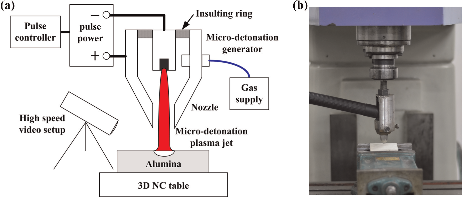
Experimental setup used in the study: (a) schematic diagram of the experimental setup and (b) the practical experimental setup.
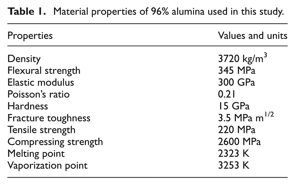
The material used in this study was 96% alumina, which was supplied by the China Building Materials Academy. The major properties of the material are listed in Table 1. In the numerical simulation, obtaining the exact material properties was necessary to generate a model closest to reality and improve accuracy. The temperature-dependent thermal properties, such as thermal conductivity, specific heat, and enthalpy, are illustrated in Figure 3. The microstructure of 96% alumina used in this study is shown in Figure 4.
Material properties of 96% alumina used in this study.
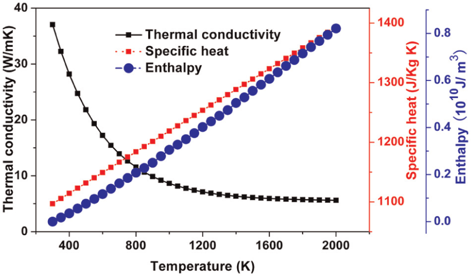
Curve of the temperature-dependent thermal properties.
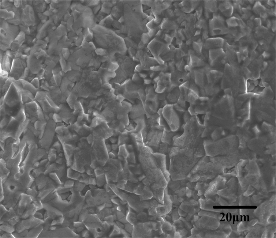
Microstructure of 96% alumina.
Experimental design
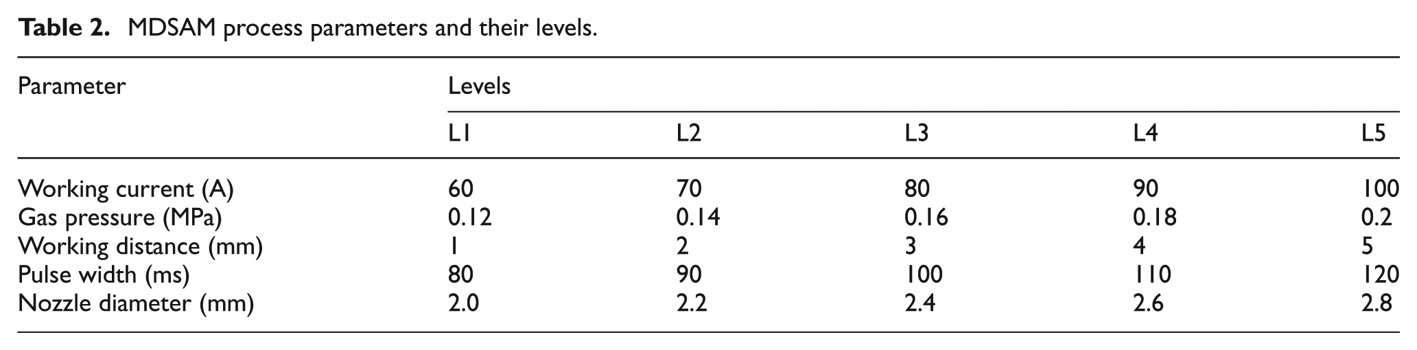
FE technique is one of the most widely used numerical simulation methods in studying the transient temperature fields and the material removal process during the thermal machining process. In this study, the ANSYS software was used and a 3D FE model for single-pulse MDSAM of alumina was developed. The Taguchi method was employed, and the orthogonal design was used to increase the information amount because the simulation is a very time-consuming process. Five major process parameters existed during the MDSAM process, which included the working current I, working gas pressure P, pulse width Ton, nozzle stand-off distance L, and nozzle diameter of micro-detonation generator D. Five levels of each parameter were selected, and the L25 (56) orthogonal array was chosen. The input processing parameters, and the levels used for the simulation are listed in Table 2.
MDSAM process parameters and their levels.
After single-pulse MDSAM, a round pit with a spherical cap shape and circular cross section was generated, as illustrated in Figure 5. The radius and the depth of the pit were determined by the process parameters of MDSAM and the materials. MRR was obtained by measuring the volume of the pit generated in the single-pulse machining. The volume of the pit can be calculated by the following equation
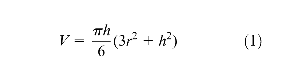
where V is the volume of the pit, r is the radius of the pit, and h is the depth of the pit.
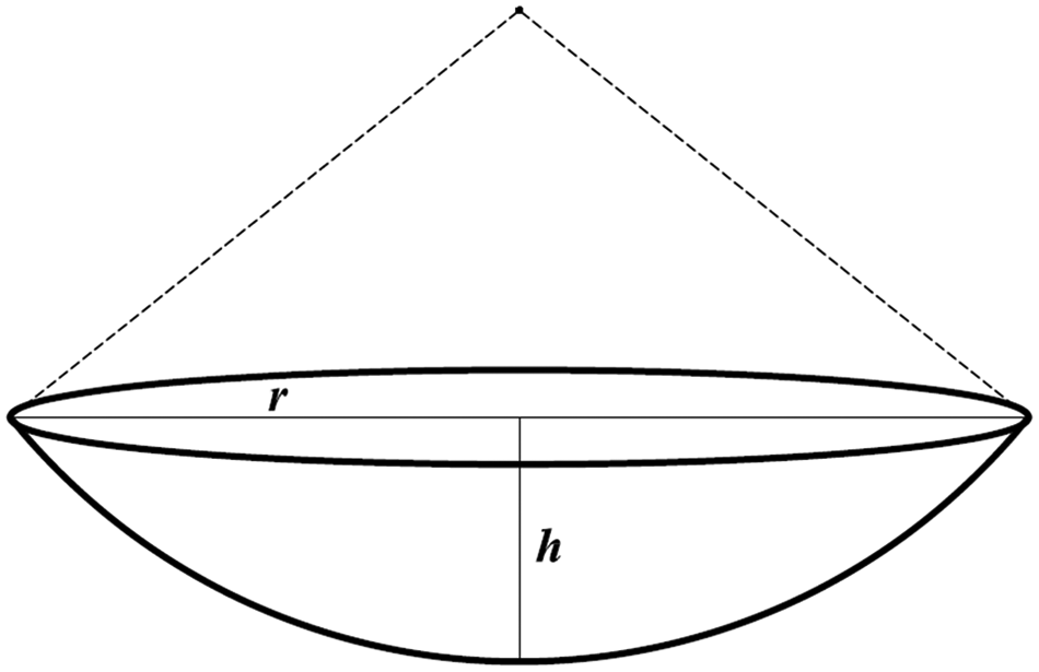
Shape of the pit after single-pulse MDSAM.
After temperature simulation, single-pulse machining of alumina was also performed to validate the simulation results. High-speed video was used to observe the shape of the micro-detonation plasma jet and the generation process of the pit. The morphology of the pit was examined by a digital microscope (Aigo GE-5). SEM (Nova Nano SEM 450/650) was employed to capture the microstructure of the pit after machining. Finally, the material removal mechanisms of alumina during MDSAM were revealed with the assistance of temperature simulation, single-pulse machining, high-speed video observation, and microstructure examination.
FE modeling
FE geometric model
In this study, a 3D FE semi-model was developed to observe the cross section of the model more conveniently after temperature simulation, as shown in Figure 6. The dimensions of the model were 4 mm × 4 mm × 1 mm. The semi-model was symmetrical with respect to the Y–Z plane, and heat load was applied on the X–Y plane. The micro-detonation machining took place at the origin with the coordinates (0, 0, 0).
3D semi-model for temperature simulation.
Heat input model
The MDSAM of alumina is a transient thermal transfer process in which the temperature complies with the law of energy conservation. The 3D non-static heat conduction equation can be described as follows
where ρ is the density of alumina, c(T) is the specific heat, λ(T) is the thermal conductivity, T is the instantaneous temperature, t is time variable, and x, y, and z are space variables.
The initial condition is

where the initial temperature T0 can be taken as room temperature. In this study, T0 = 300 K.
The boundary condition is the heat convection condition that can be written as
where R stands for the radius of the micro-detonation plasma jet, h is the heat convection coefficient, and q(x, y) is the heat flux density distribution of the micro-detonation plasma jet. The micro-detonation plasma jet was considered the surface heat source in the FE model. The heat current density of the heat source adheres to the Gaussian distribution, which can be expressed as follows
where η is the energy transfer ratio and U is the voltage of the micro-detonation plasma jet. The value of η ranges from 0.22 to 0.3, depending on the nozzle stand-off distance. U is a function of working current, working gas pressure, and nozzle diameter, which is obtained by the preceding experiment. U is represented by the following equations
The MDSAM of alumina is a very complex process. Although the process is attempted to be defined accurately in the FE model, some physical phenomena have to be neglected due to the complicated and indefinite nature of the machining. The following were the assumptions used in the simulation:
The workpiece is homogenous and isotropic.
The surface is not influenced by MDSAM and is regarded as an adiabatic boundary.
The molten and evaporated materials are simplified.
The heat flux of the micro-detonation plasma jet follows the ideal Gaussian distribution.
The simulated diameter and depth of the machined pit were measured in the model and compared with the corresponding experimental results. The temperature curves along the x- and z-axes were plotted to study the influences of processing parameters on MRR and to ascertain the material removal mechanisms involved in the MDSAM of alumina.
Results and discussion
High-speed video observation
The effect of working current on the micro-detonation plasma jet was investigated at fixed gas pressure, pulse width, nozzle stand-off distance, and nozzle diameter. The parameters used in the plasma jet observation were set as follows: I = 40, 60, 80, and 100 A; P = 0.16 MPa; Ton = 120 ms; L = 10 mm; and D = 2.4 mm. The nozzle stand-off used a value of 10 mm, which was much bigger than the range of normal values, to observe a more complete plasma jet. The results of the observation are shown in Figure 7. When the working current was too small, the energy density provided by the power was so low that the micro-detonation plasma jet could not be produced. Figure 7(a) shows that the plasma jet of 40 A is very weak and does not have detonation characteristics. When the working current is more than 50 A, the stable micro-detonation plasma jet can be obtained. The images of the stable plasma jet with different working currents are shown in Figure 7(b)–(d). The diameter of the plasma jet increased with the increase in working current. The difference was in the increase of temperature as the working current increased. Higher temperature caused the expansion of the plasma jet column and the increase in diameter.
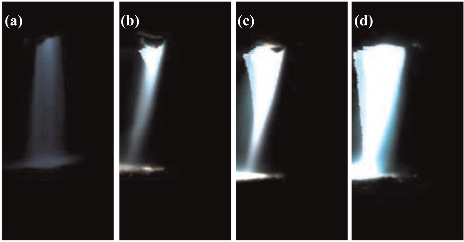
Images of the micro-detonation plasma jet at (a) I = 40 A, (b) I = 60 A, (c) I = 80 A, and (d) I = 100 A.
An observation of the material removal process during the single-pulse MDSAM was conducted. The results are shown in Figure 8. The parameters were I = 80 A, P = 0.16 MPa, Ton = 80 ms, L = 3 mm, and D = 2.4 mm. Figure 8(a) shows that the micro-detonation plasma jet is sprayed very weakly from the nozzle at 3 ms. The plasma jet became stable at 5 ms and was applied on the workpiece surface where the material removal process began (Figure 8(b)). As the process continued, the ablation zone gradually expanded (Figure 8(c)–(g)), and the melting alumina drops spattered along the radial direction. The plasma jet vanished (Figure 8(h)) at the end of the single-pulse machining of 80 ms, and an ablation pit was produced.
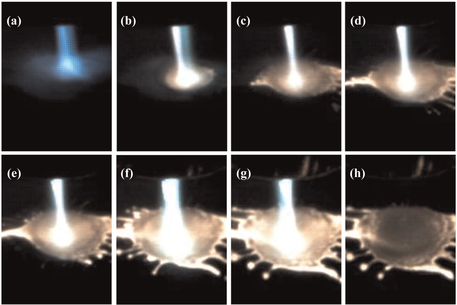
Images of the material removal process in the alumina machining at (a) 3, (b) 5, (c) 10, (d) 15, (e) 20, (f) 50, (g) 79, and (h) 80 ms.
Figure 9(a) shows the top view of the pit after the single-pulse machining. The pit had a spherical cap shape and its cross section approximated a circle. The pit size had a diameter of 2 mm and a depth of 0.3 mm. The alumina melted as the processing region reached a temperature above melting point, as shown in Figures 8 and 9. Part of the melting alumina spattered in the radial direction under the impact force of the micro-detonation plasma jet and formed the spatter deposition. A clear spatter deposition is shown in Figure 9(b).
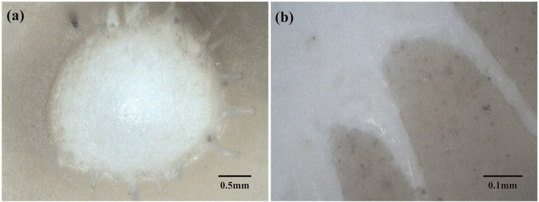
Pit produced by a single-pulse MDSAM: (a) top view and (b) micrograph of the spatter deposition.
SEM was employed to observe the micrographs of the machined pit after the MDSAM of alumina. The surface of the pit bottom is illustrated in Figure 10(a). Several small craters and micro-cracks were found on the machined surface. The craters showed a similar shape but had different sizes and depths. The craters were generated by the sublimation effect when the temperature in the pit was above the boiling point of the alumina. The micro-cracks were mainly produced by the different cooling speeds, whereas the melting materials were recasted after MDSAM. The spatter deposition, small craters, and micro-cracks may cause many machining defects in the materials. Therefore, the machined surface for alumina machining with MDSAM is very rough and must be dressed via post-processing method.
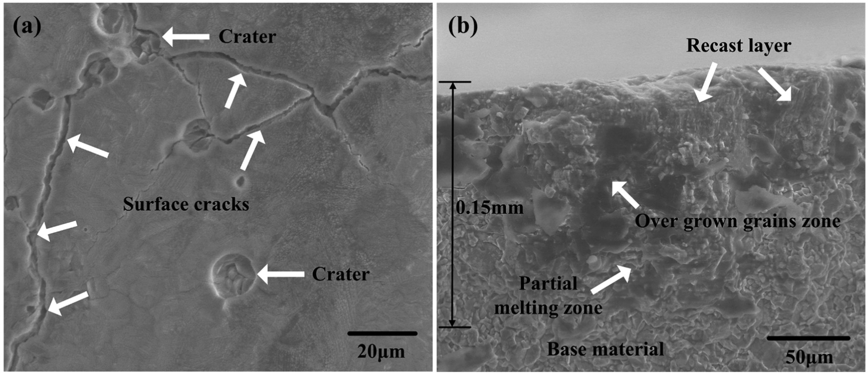
SEM microstructure of the machined pit: (a) surface and (b) cross section.
The microstructure of the cross section at the bottom of the pit is shown in Figure 10(b). The cross section of the pit was divided into four parts, including the recast layer, overgrown grain zone, partial melting zone, and base material. The molten materials formed the recast layer. The grains, as part of the recast layer, grew and formed a column shape along the direction of the temperature gradient. The other part of the recast layer showed an amorphous morphology. The zone with the overgrown grains was adjacent to the recast layer. In this zone, the noticeable thermal effect induced the overgrowth of grains. In the partial melting zone, the grains were partially melted and then resolidified into the glassy phase. Under typical process parameters, the thickness of the heat-affected zone in the MDSAM of alumina was about 0.15 mm. Thus, after the MDSAM of alumina, post-finish machining was needed to remove about 0.15 mm thickness.
Initial results of simulation
A typical set of process parameters (I = 80 A, P = 0.16 MPa, Ton = 100 ms, L = 3 mm, and D = 2.4 mm) was selected for the initial study. The simulated temperature field generated by single-pulse micro-detonation machining for alumina is shown in Figure 11. The maximum temperature was located at the center of the micro-detonation point with a value of 13,540 K. The temperature of the alumina at the molten region reached its melting point of 2323 K.
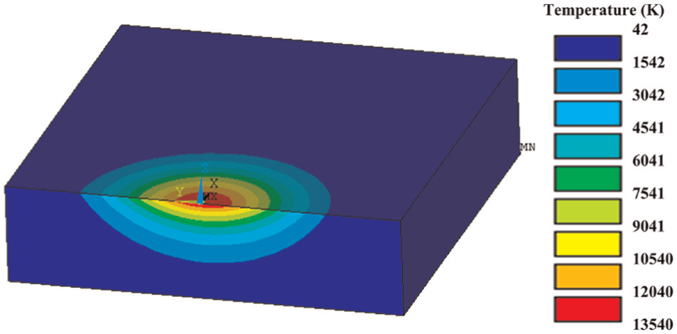
Temperature field after single-pulse MDSAM.
Figure 12(a)–(c) shows the temperature distribution at the micro-detonation point and along the x and z directions, respectively. The temperature gradually increased with the increase in machining time, as shown in Figure 12(a). At the end of the pulse width, the temperature reached its highest value. Figure 12(b) shows the variation of temperature along the x direction. At the material removal region (x < 1.1 mm), the temperature rapidly decreased. The temperature outside the pit (1.1 mm < x < 4 mm) slowly decreased and failed to reach the melting point. Figure 12(c) shows the temperature along the z direction. The more absolute the z value is, the lower the temperature. The cross section of the material removal area was 0 mm < z < 0.5 mm.
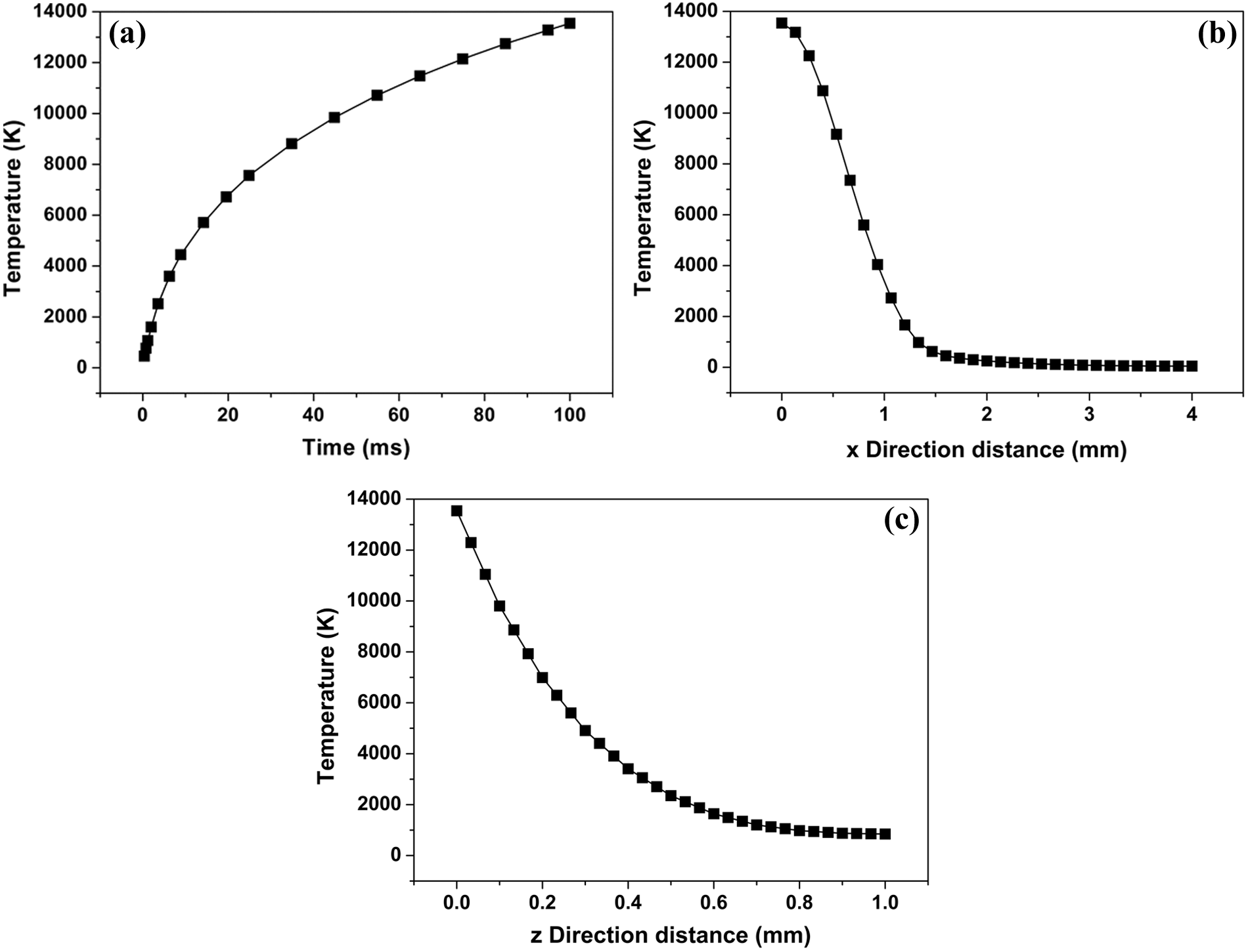
Temperature distribution (a) at micro-detonation point, (b) along the x direction, and (c) along the z direction.
The experimental trial was performed to validate the simulation result. The same parameter set was employed in the simulation. Figure 13 shows the simulated result (right side) and the corresponding experimental result (left side), including the cross-sectional profile of the pit. The cross section of the simulated pit was in good agreement with that of the experiment. The 2.2 mm diameter of the machined pit was similar to the simulated diameter. The depth of the machined pit was 0.34 mm, which was smaller than the 0.5 mm simulation result. The difference in depth can be ascribed to the heat effect on the zone at the bottom of the pit. Figure 10(b) shows the heat-affected zone at the bottom of the pit with a thickness of 0.15 mm. If both the depth of the machined pit and the thickness of the heat-affected zone are considered, the total depth of the pit would be about 0.49 mm, which is very close to the simulated depth of 0.5 mm. The corresponding experiment validated the simulation result and proved that the finite model is appropriate.
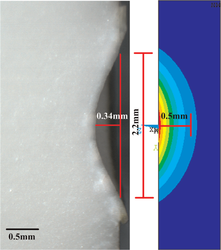
Cross-sectional view of the pit generated by the experiment (left side) and simulation (right side).
Material removal mechanism
When the SEM image of the machined pit, temperature simulation, and properties of alumina are combined with the results of high-speed video observation, the material removal mechanism of alumina in the MDSAM process can be deduced. The material absorbed a large amount of heat, and the temperature gradually increased while the high-temperature micro-detonation plasma jet was applied on the surface of the alumina. At the end of the single-pulse duration, part of the materials at the center of the pit had a temperature above the boiling point. These materials were removed by sublimation method, which generated many craters on the machined pit. The part of the materials with temperature reaching melting point was removed by melting method. The micro-detonation had a high impact force, and part of the melting materials was thrown out from the pit by the impact effect, forming spatter deposition. The other melting materials cooled in the pit and generated a recast layer. Phase transformation phenomenon occurred at the subsurface of the bottom of the machined pit and produced the grains at the overgrown zone and partial melting zone. In conclusion, when alumina ceramics were machined with MDSAM, the materials were removed by a combination of sublimation, melting, and phase transformation under the synergistic effect of high temperature and high impact force of the micro-detonation plasma jet.
Analysis of the Taguchi method
Table 3 presents the L25 orthogonal array based on the Taguchi method, as well as the observed values of the highest temperature and MRR. The highest temperature was obtained by simulation, whereas MRR was calculated using equation (1). In equation (1), the depth of the pit h is the practical value, which is measured by experimental method. Analysis of variance (ANOVA) of the experimental data was conducted to obtain the significant process parameters and the optimal combination levels of the process parameters associated with the highest temperature and MRR. The influence of the process parameters was considered significant if the calculated F ratio values exceeded F0.05(4, 4).
Orthogonal array and observed values of highest temperature and MRR.
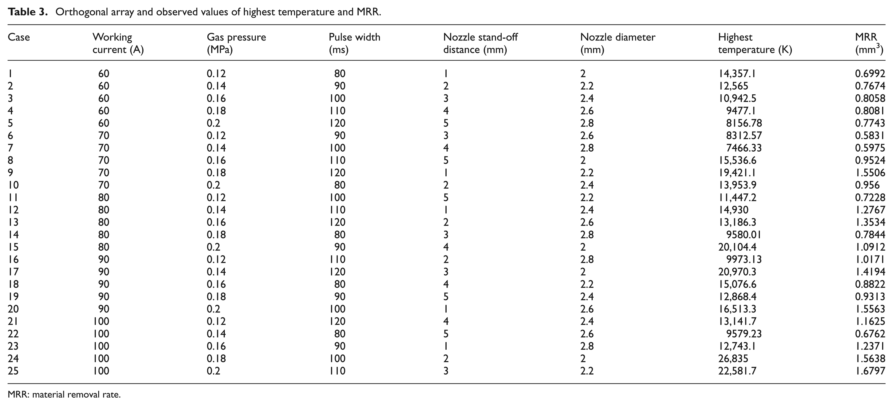
MRR: material removal rate.
ANOVA of the highest temperature and MRR
Using the data in Table 3, ANOVA of the highest temperature was performed. The results are presented in Table 4. In Table 4, the nozzle diameter had the most significant influence on the highest temperature, followed by the working current and gas pressure. The pulse width and nozzle stand-off distance had less significant contributions to temperature.
ANOVA of highest temperature.
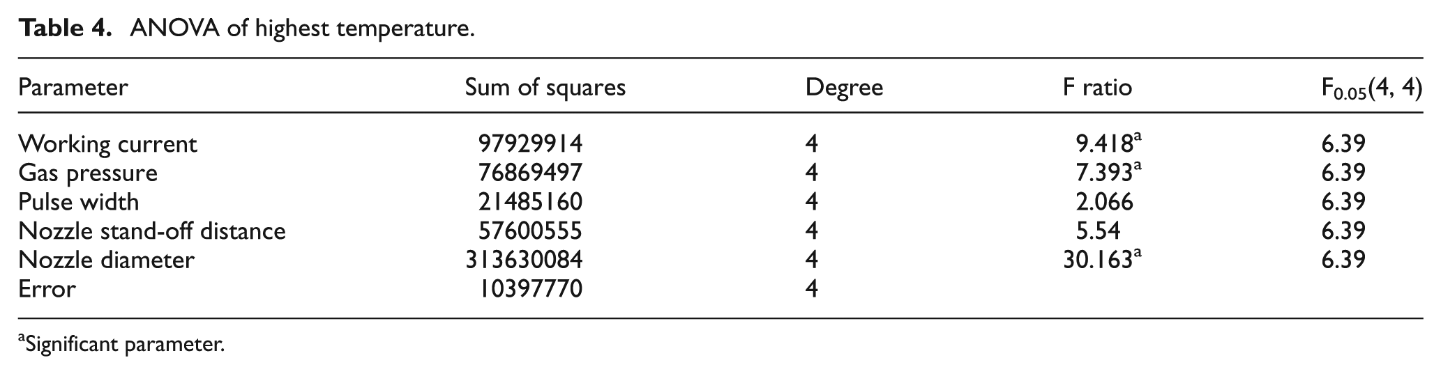
Significant parameter
Table 5 shows the result of the ANOVA of MRR obtained from the L25 array in Table 3. As shown in Table 5, the working current, pulse width, and nozzle stand-off distance had significant contributions to MRR. The working current had the most significant effect on MRR, whereas the pulse width and nozzle stand-off distance had almost the same influence.
ANOVA of MRR.
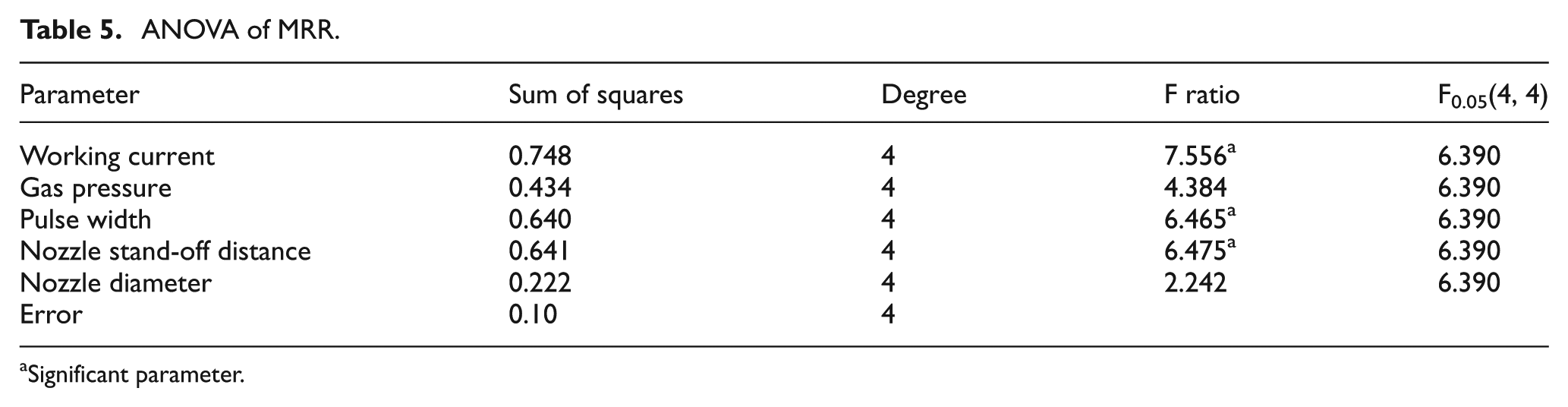
Significant parameter
Effects of parameters on the highest temperature and MRR
The average values of the highest temperature and MRR at each level for the five process parameters were calculated to determine the parameter effects. The relationship between the process parameters and the highest temperature and MRR can be obtained when the process parameters are taken as the abscissa and the highest temperature as the vertical coordinates. Figure 14(a)–(e) illustrates the effects of the working current, gas pressure, pulse width, nozzle stand-off distance, and nozzle diameter on the average values of the highest temperature and MRR, respectively.
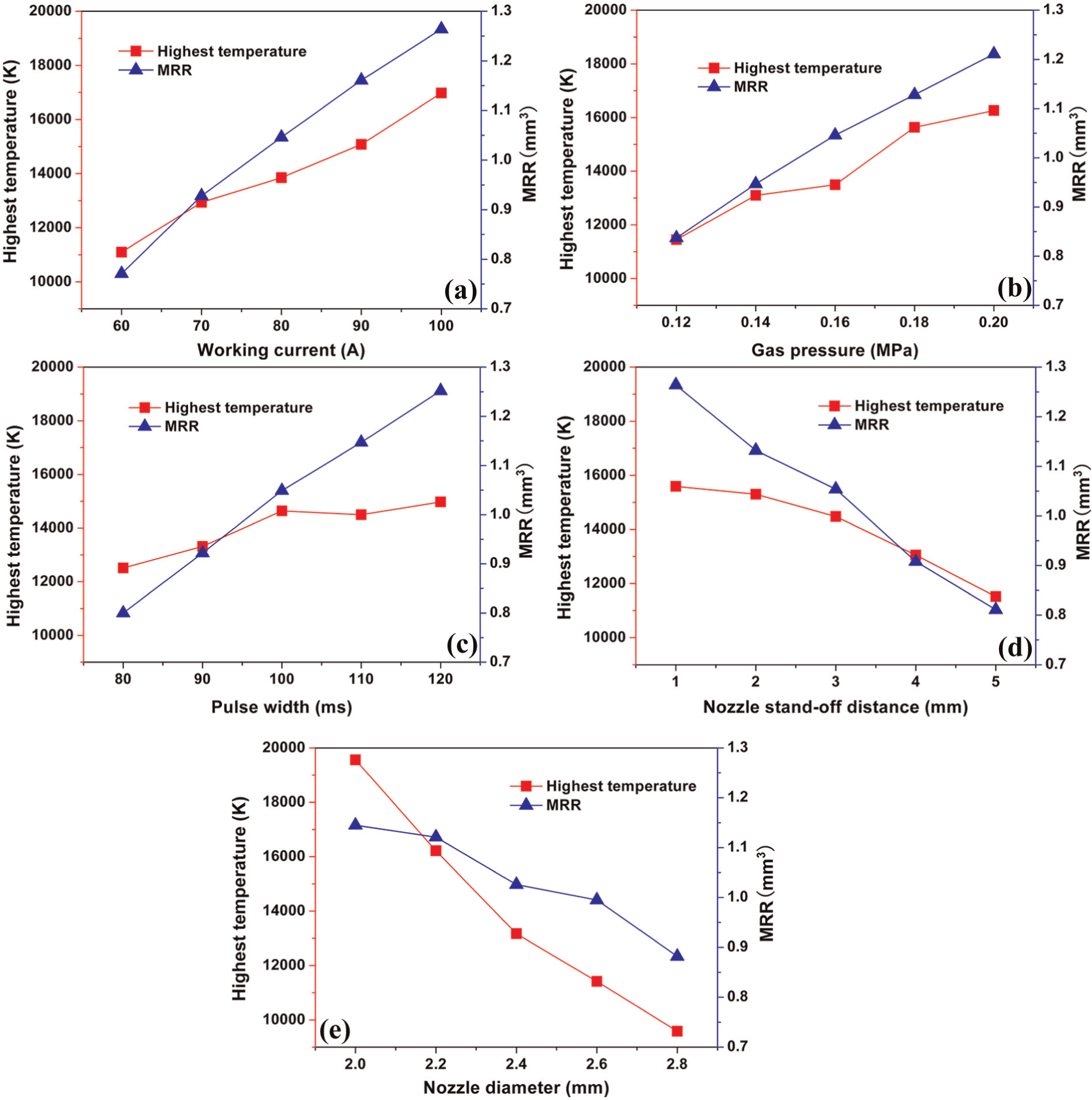
Effect of the process parameters on the highest temperature and MRR: (a) working current, (b) gas pressure, (c) pulse width, (d) nozzle stand-off distance, and (e) nozzle diameter.
In Figure 14, the highest temperature and MRR have the same relationship with the process parameters. The highest temperature and MRR increased with the increase in the working current, gas pressure, and pulse width, but decreased with the increase in nozzle stand-off distance and nozzle diameter. In general, these phenomena can be explained by equations (5) and (6). From the two equations, the single-pulse energy had a direct proportion with the working current and gas pressure and an inverse proportion with the nozzle diameter. Therefore, the highest temperature and MRR increased with the increase in working current and gas pressure (Figure 14(a) and (b)), but decreased with the increase in nozzle diameter (Figure 14(e)). Moreover, the output energy noticeably increased with the increase in pulse width. A longer pulse width increased the processing duration, which caused the augmentation of the highest temperature and MRR (Figure 14(c)). In equation (5), η is the energy transfer ratio of the micro-detonation plasma jet, and its value depended on the nozzle stand-off distance. The energy transfer ratio η had an inverse proportion with the nozzle stand-off distance. When the value of the nozzle stand-off distance was 1 mm, the energy transfer ratio η had the highest value of 0.3. Therefore, the highest temperature and MRR increased with the increment of the nozzle stand-off distance (Figure 14(d)).
Optimal combination of parameters
Since MDSAM is a rough machining method for engineering ceramics, the machining efficiency is the priority goal to be considered and the bigger MRR is our expectative target. The high temperature may cause thermal damage to the workpiece, so the highest temperature should be as low as possible. Based on the ANOVA and the effects of parameters on the highest temperature and MRR, we know that the working current, pulse width, and nozzle stand-off distance have significant contributions to MRR. Meanwhile, the bigger working current and pulse width and the smaller nozzle stand-off distance lead to bigger MRR. Therefore, the values of the three parameters should be I = 100 A, Ton = 120 ms, and L = 1 mm. As the working gas pressure and nozzle diameter have insignificant influence on MRR, the objective should be smaller temperature. So the values of working gas pressure and nozzle diameter are P = 0.12 MPa and D = 2.8 mm. The optimal combination of parameters is presented as follows: I = 100 A, P = 0.12 MPa, Ton = 120 ms, L = 1 mm, and D = 2.8 mm.
Conclusion
The MDSAM of alumina was investigated in this study. The shape of the micro-detonation plasma jet and the MDSAM process were observed by high-speed video. The material removal mechanism for alumina machined by MDSAM was obtained by temperature simulation and the corresponding experiments. The effects of the process parameters, which included working current, gas pressure, pulse width, nozzle stand-off distance, and nozzle diameter, on the highest temperature and MRR were studied using the Taguchi method and ANOVA. Some of the conclusions are as follows:
The micro-detonation plasma jet could be generated when the working current is too low. The diameter of the jet increases with the increase in working current. After single-pulse machining, a pit with the shape of a spherical cap is generated. The surface of the machined pit is full of small craters and micro-cracks. The heat-affected zone at the cross section of the pit bottom can be divided into four layers, namely, the recast layer, overgrown grain zone, partial melting zone, and base material. The thickness of the heat-affected zone is about 0.15 mm.
In the typical process parameters, the highest temperature can reach 13,540 K at the center of the micro-detonation point. The simulated pit has a diameter of 2.2 mm and a depth of 0.5 mm, whereas the corresponding experimental result indicates a pit with the same diameter but smaller depth of 0.34 mm. Considering the thickness of the heat-affected zone, the result in the simulation result is the same as that in the experiment.
For alumina ceramics machined with MDSAM method, the materials are removed by a combination of sublimation, melting, and phase transformation under the synergistic effect of high temperature and high impact force of the micro-detonation plasma jet.
The working current, gas pressure, and nozzle diameter have significant influences on the highest temperature, whereas the working current, pulse width, and nozzle stand-off distance have significant contributions to MRR. Both the highest temperature and MRR increase with increase in the working current, gas pressure, and pulse width, but decrease with increase in the nozzle stand-off distance and nozzle diameter. The optimal combination of parameters is I = 100 A, P = 0.12 MPa, Ton = 120 ms, L = 1 mm, and D = 2.8 mm.
Since MDSAM is a rough machining technology for engineering ceramics, grinding, polishing, or other finish machining methods are needed to recover the machining quality after MDSAM. Another method to control the machining quality is parameter optimization, which we will further investigate. In the further study of the parameter optimization, the machining efficiency, quality, and cost will be comprehensively considered and the spatter deposition area of pit, surface roughness, bending strength, and thickness of heat-affected zone will serve as the object of machining quality.
Footnotes
Declaration of conflicting interests
The authors declare that there is no conflict of interest.
Funding
This study was supported by the National Nature Science Foundation of China (grant number 51075399) and Beijing Natural Science Foundation (grant number 3132022).