
Abstract
Ball-end milling cutter with tooth offset center is widely used in machining industry, because it has higher machining efficiency and better stability compared with the ball-end milling cutter without tooth offset center. In addition, the tooth offset center has lower wear rate of the tool tip so the life of the milling cutter is improved. However, up to present, there is no mature and effective theory for the design and manufacture of this kind of milling cutters. This article presents a new mathematical model for S-shaped edge curve of the ball end taking the tooth offset center into account, which can construct accurate S-shaped edge curve for the ball-end cutting tools with tooth offset center as well as without tooth offset center. This model overcomes the complex computation and bad adaptability of the traditional modeling method. At the same time, a five-axis grinding algorithm for rake face of the ball end is also presented in this article. Finally, based on the application programming interface of CATIA™, a three-dimensional computer-aided design and computer-aided manufacturing system is developed. The accuracy and effectiveness of the grinding algorithm are verified by simulation in VERICUT™ and machining experiment in tool grinding machine.
Introduction
Ball-end milling cutter is the major tool in the milling of curve surface, and it is widely used in manufacturing industry, such as mold, sculptured dies, aerospace, machinery and electronic manufacturing fields. At present, according to the structure of cutting edge, the ball-end milling cutter can be divided into two types: the first one is the ball-end milling cutter without tooth offset center, as shown in Figure 1, whose edge curve directly extends to the tooth tip of ball end. Another one is the ball-end milling cutter with tooth offset center, as shown in Figure 2, and the characteristic of this kind of cutter is that there is offset distance between the edge curve and the tooth tip. By comparison, because the tooth offset center makes the cutting edge in the tooth tip more solid, the ball-end milling cutter with tooth offset center shows better material removal rate and lower wear rate of the tooth tip in high-speed numerical control (NC) machining. And it has much wider application. However, this kind of cutter is more difficult to be designed and manufactured because of the tooth offset center. Although there is a complete set of theory that can be used to design and manufacture the ball-end milling cutter without tooth offset center at present, it cannot be applied directly to the ball-end milling cutter with tooth offset center, so it is significant to research a reliable theory for the design and manufacture of this kind of cutter.
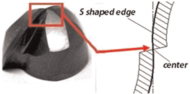
Cutter without tooth offset center.
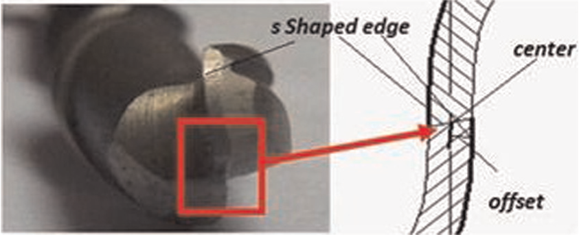
Cutter with tooth offset center.
In the milling cutter manufacturing, precise design is a basic premise of manufacturing, so in order to manufacture precise milling cutter, the modeling design theory must be studied first. Generally, the end-tooth of ball-end milling cutter mainly includes the rake face, flank face and the edge curve. In the cutter modeling, the rake and flank faces are formed based on the edge curve. Furthermore, the edge curve is also the guideline of the grinding wheel movement during grinding process. Therefore, the edge curve should be the major research object. Many researchers have done much research about it since the ball-end milling cutter appears in 1981. Tsai and Hsieh 1 presented an analysis method integrates design, manufacturing and numerical simulation to obtain suitable manufacturing model of the design and NC manufacturing of ball-end cutters and a helical edge curve with constant helix angle on the cylinder and the ball-head, the exact solution of the helical groove cross-sectional equation and the mathematical model of the grinding wheel cross section. In order to produce the exact shapes of helical cutting edges and grooves, Chen et al. 2 first defined the helical angle as the angle between the tangential vector of screw line and the revolving axis on the circular-arc ball-end milling (CABEM) cutter. The shapes of cutting edge curves and groove surfaces of the CABEM cutter are systematically designed and manufactured using a proposed procedure of differential geometry and inverse envelope theory. Chen 3 also finds a mathematical solution to the design and manufacturing problems of ball-end cutters having a cutting edge with constant angle to the axis to resolve two problems of the mathematical description of the cutting edge at the top of the ball-end cutter and the grinding wheel feeding speed description to approach infinity in the same region. Altintas and Engin4,5 gave generalized mathematical models of arbitrary end mills and inserted cutters, and the model allows parametric design and representation of a variety of end mill shapes and helical flutes.
Various researchers1–5 designed a cutting edge of S-shape by defining the helix angle of the edge curve of ball-end milling cutter, which is the included angle between the curve and the cutter axis. But because the mathematical model is not valid in the tooth tip of ball end, the curve cannot extend to the tooth tip of ball end. So other shape of the edge curve must be employed to revise it. On the basis of this, He et al. 6 proposed generalized helical movement and established the general mathematic model of the typical ball-end edge curve, including equal helical pitch curve and equal helical angle curve. Liu and Liu 7 devised a planar edge curve to express the edge of ball-end mill and discussed the formed principle and the processing method of the special revolving tool with this planar edge curve. But the “S” shape of planar edge curve is not good, and the calculation is very complexity. So, Pham and Ko 8 built the mathematical model of the rake face, rear face and cutting edge of the ball-end milling cutter with orthogonal S-shaped edge curve, based on the analysis of the grinding method, and solved the problem about the smooth connection between the ball-end edge curve and the cylindrical helix edge.
Until now, several curves are used as the edge on the ball-end milling cutter, such as orthogonal helix edge curve, equal helix angle edge curve and planar edge curve. Among them, the orthogonal helix edge curve has better S-shape and more simple mathematical computation comparing with the latter two kinds. Although all of these curves can smooth connection with the helix on the circumferential teeth and they extend to the tip of ball end in order to increase the structural strength, and there is certain offset distance from the tip of ball end these have difficulties for this case. Namely, the curve on the ball end consists of two sections, one is the approaching curve and the other is the orthogonal helix edge curve or equal helix angle edge curve or planar edge curve; however, this would inevitably increase the complexity of the modeling of the edge curve and also difficult to ensure the continuity of the curve. Besides the difficulty of mathematical models of edge curve, another concern is how to grind the end-milling cutter precisely. The manufacturing and simulation solutions of the end mill are also studied by many researchers. Kang et al. 9 presented the manufacturing models for revolving-arc milling cutters. Zhang and Yao 10 presented the algorithm of cutting edge of cutter with a constant helical angle. Lai and Chen 11 studied the machining method of NC machining of tapered ball-end milling cutters. Du et al. 12 discussed the NC machining of the ball-end milling cutter by the five-axis tool motions. Bao et al. 13 studied a virtual manufacturing model of a revolving milling cutter in two-axis NC processing. Xiong and Bin 14 and Chen and Bin 15 proposed a grinding method using a cubic boron nitride (CBN) spherical grinding wheel to decrease the number of simultaneous cooperative axes of a computer numerical control (CNC) tool grinder and to realize the smooth transition of rake face. Hsieh 16 proposed a mathematical model for manufacturing the helical flute and cutting edge curve of truncated-cone ball-end cutter. Mounayri et al. 17 introduced a special type of artificial neural networks to establish the relationship between the machining conditions and process parameters for the case of the ball-end milling cutter. Chen et al. 18 discussed a novel mathematical model for grinding ball-end cutter with equal rake and clearance angle to easily grind the rake face and the rear face on a same grinding machine. Lv et al. 19 gave a new type of taper ball-end milling cutter and made some virtual manufacturing on two-axis machining tools. Han et al. 20 researched a non-NC machining method for two kinds of revolving cutter.
In the above-mentioned studies, the majority of the researches were focused on grinding of the ball-end milling cutter without tooth offset center. However, as to the ball-end milling cutter with tooth offset center, no better solutions were found. For the grinding of the ball-end milling cutter without tooth offset center, there are large numbers of research results based on the mature theory of edge curve design. However, the edge curve with tooth offset center established by existing methods is complex, which brings certain difficulty for grinding.
In summary, most previous studies focused on the design and manufacturing theories of the ball-end milling cutter without tooth offset center on the top of the ball end, as shown in Figure 1. But these theories are no longer suited to the ball-end milling cutter with tooth offset center, as shown in Figure 2. So this article presents a new mathematical model for S-shaped edge curve of the ball end taking the tooth offset center into account, and it can accurately describe the curve both with and without tooth offset based on the theory of the orthogonal helical S-shaped edge curve. Based on this, a grinding algorithm for the rake face of ball end is researched in this article. Subsequently, the three-dimensional (3D) models of ball-end milling cutter are designed with CATIA™; finally, a grinding experiment is carried out after 3D grinding simulation with VERICUT™, and a ball-end milling cutter with tooth offset center and a ball-end milling cutter without tooth offset center are machined, and measurements of the cutter products showed that their sizes meet the design requirements, so the design and manufacturing theories presented in this article can be used to the ball-end milling cutter with tooth offset center as well as the ball-end milling cutter without tooth offset center.
This article is organized as follows: In section “Modeling of ball-end milling cutter considering the value of tooth offset center,” the mathematical model of the S-shaped edge curve with the value of the tooth offset center is described, which ensures the smooth connection of S-shaped edge curve with circumferential edge curve. In section “Grinding algorithm of the rake face of ball-end milling cutter,” a grinding algorithm of rake face of ball-end milling cutter is presented. In section “3D design and machining experiment of ball-end milling cutter,” the 3D design and simulation software for the ball-end milling cutter are implemented by the use of the secondary development of software CATIA and VERICUT, and a grinding experiment is carried out in a five-axis grinder to check the feasibility of the mathematical model and the grinding model of the ball-end milling cutter in the visualized mode. In section “Conclusion,” conclusions and future study are presented.
Modeling of ball-end milling cutter considering the value of tooth offset center
Mathematical model of S-shaped edge curve
As shown in Figure 3, the mathematical model of S-shaped edge curve is derived. First, the coordinate system of Os-XsYsZs in the center of sphere is set up, and the Zs-axis coincides with the axis of ball-end milling cutter. A helix edge curve keeps equal helical angle with the guide line of S-shaped edge curve. A straight line which parallels to the XsYs plane and is tangent to the cylinder with radius of h is made through the points of guide line. And the intersection points of straight line and spherical surface form the S-shaped edge curve of ball-end milling cutter. Here, h is the distance of the tooth offset the center from the top view of ball-end milling cutter. If h = 0, the S-shaped edge curve is ball-end orthogonal helical edge curve through the ball end. In other word, the model of the S-shaped edge curve made by this method is consistent with the model of orthogonal helical edge curve. If h≠ 0, the S-shaped edge curve is formed with the value of the tooth offset the tooth tip center.
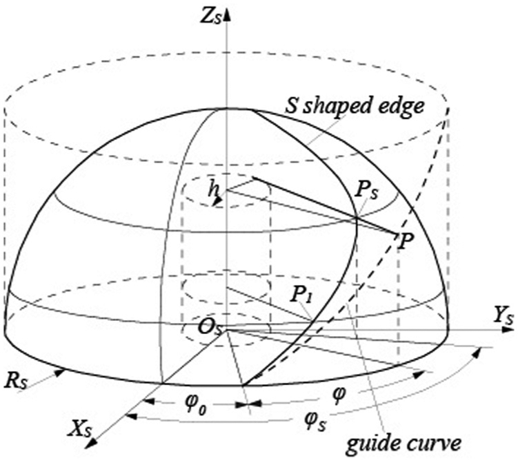
Schematic diagram of S-shaped edge curve
The S-shaped edge curve equation is

where θ is colatitude angle, φs(θ) is rotating angle of the S-shaped edge curve and the parametric expression of φs(θ) based on parametric variable of θ is

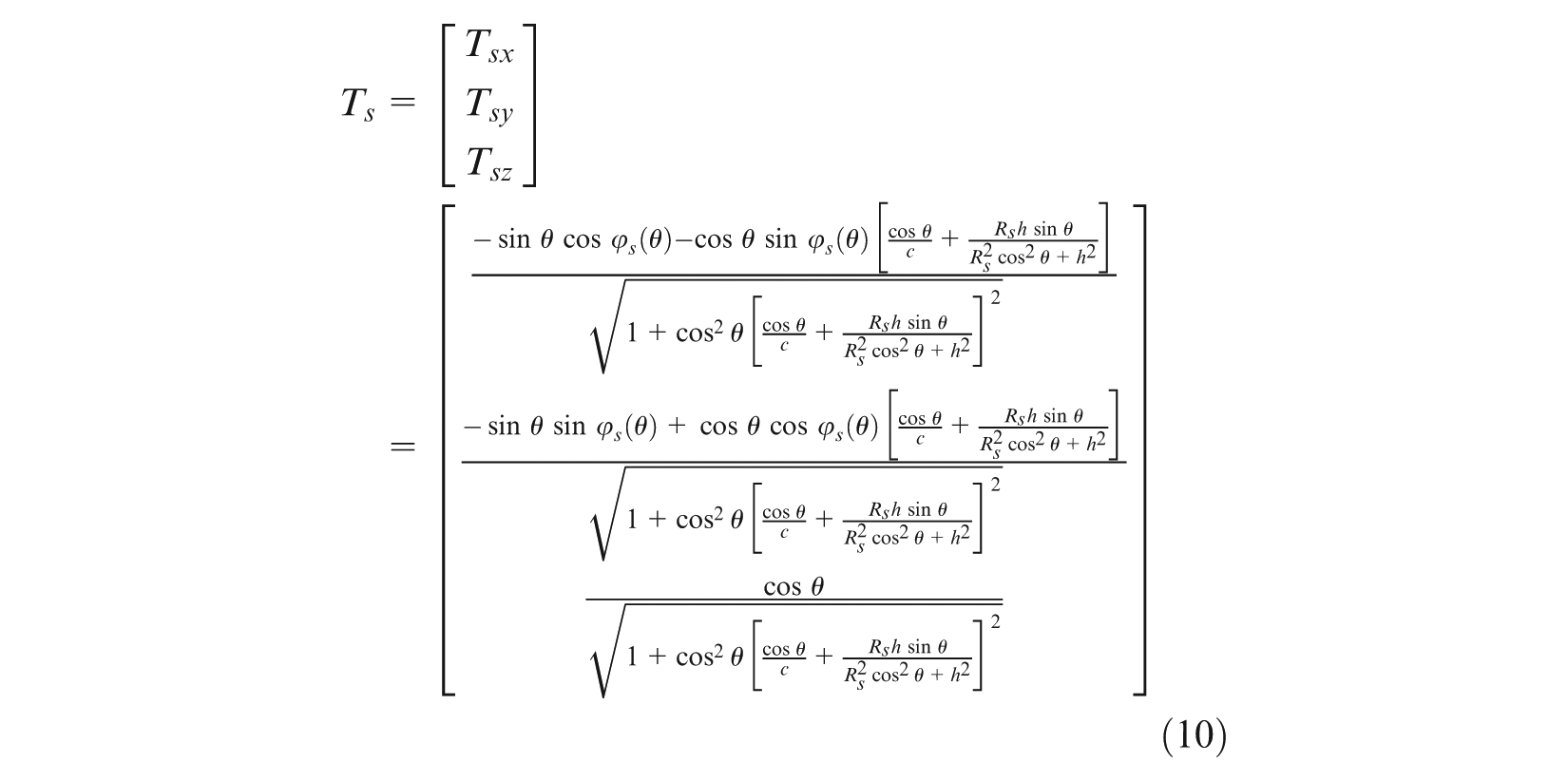
Account for the derivation calculus to equation (1), the unit vector of any point of S-shaped edge curve can be obtained

And, the unit tangential vector of revolved-body generatrix of any point of S-shaped edge curve of ball end is re, then

The definition of the helix angle is the angle between the tangential vector of the helix of edge curve and the tangential vector of revolved-body generatrix. If the helix angle of any point of S-shaped edge curve on the ball surface is βs, then it can be derived by equations (2) and (3)

Consequently, the key solution of equation of S-shaped edge curve is the relation between φs(θ) and θ. Based on the relation between φs(θ) and φ (rotation angle of guide helical curve), the expression of φs(θ) can be obtained.
The equation of guide helical curve in the cylinder is

where Rw is the radius of cylindrical surface with the helical curve, and Rw = Rs, c = 1/tanω, where ω is helical angle.
Supposed that P is the point of the guide helical curve and Ps is the point of the S-shaped edge curve corresponding to point P (Figure 4). It means the line through the point P and Ps parallels to the XsYs plane and tangent to the central cylinder. So, Rs sin θ = Rscφ, and the relation of φ and θ is φ = sin θ/c.
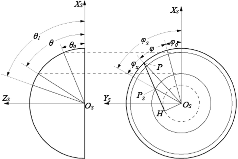
Rotating angle of S-shaped edge.
As shown in Figure 4, φs(θ) = ∠HPsOs−∠HPOs = arcsin(h/(Rs cos θ)) − arcsin(h/Rs). The relation of φ and φs(θ) is

So


Equations (7) and (8) are transferred into equations (1) and (2). Based on parametric variable of θ, the equation of edge curve, unit tangential vector and helix angle are obtained, respectively


Smooth connection of S-shaped edge curve with circumferential edge curve
First-order smooth connection of S-shaped edge curve and circumferential edge curve can be applied with the following two requirements (Figure 5):
The original rotating angle of S-shaped edge curve and the terminal rotating angle of circumferential tooth are equal;
The original unit tangential vector of S-shaped edge curve and the terminal unit tangential vector of circumferential tooth are equal.
Initial rotating angle of S-shaped edge.
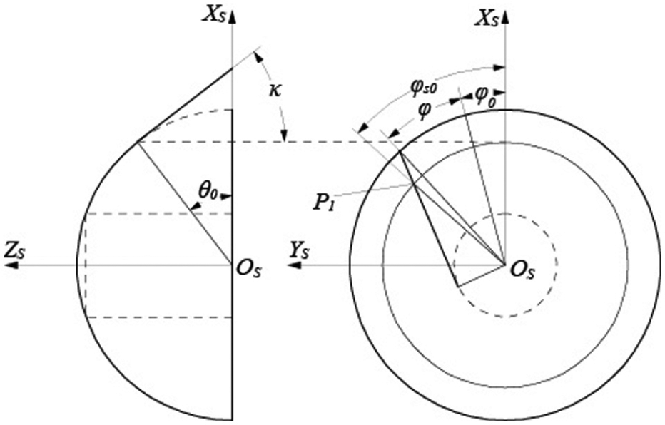
In section “Mathematical model of S-shaped edge curve,” the model of the S-shaped edge curve is built under assumed condition of supposed contour of circumferential tooth is cylinder, and the intersection point Q of the S-shaped edge curve and circumferential tooth curve is in the XsYs plane, which means θ0 = 0 (θ0 is original latitude angle of S-shaped edge curve). In such case, first-order smooth connection of the S-shaped edge curve and circumferential edge curve is easily realized when the helical angle of the guide helical curve and terminal helical angle of the circumferential tooth are equal. But if some part of circumferential tooth curve is conical helix, the point Q is not in the XsYs plane, which means θ0≠ 0, in this case, it is difficult to get the helical angle of the guide helical curve. The value of ω determines smooth connection of the S-shaped edge curve and circumferential edge curve. In the following, the solving method of ω is studied.
Supposing that point P1 is the intersection point of the S-shaped edge curve and circumferential edge curve, and the angle β (terminal helical angle of the circumferential tooth), φ1 (terminal rotating angle of the circumferential tooth) and κ (tapered angle of the circumferential tooth) are known. And then, it is easy to find θ0 = κ (θ0 is original latitude angle of the S-shaped edge curve). According to equations (7) and (10)

where Ts0 is the original unit tangential vector.
Base on the definition of generalized helical angle, Tc (the terminal unit tangential vector of the circumferential tooth) is

In order to meet the conditions 2), let Tcx = Ts0x, Tcy = Ts0y, Tcz = Ts0z, so

And based on φ1= φs0

Equation (15) is transferred into equation (7); the complete equation of φs(θ) can be derived

Model result of S-shaped edge curve
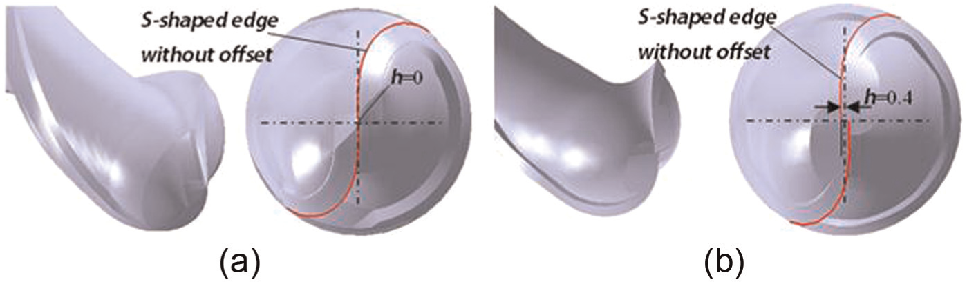
Apparently, the mathematical model of edge curve established in this article can be applied to two kinds of edge curves. When the value of tooth offset center h = 0, an edge curve without tooth offset center can be obtained, as shown in Figure 6(a). On the other hand, an edge curve with tooth offset center can be obtained when h≠ 0, as shown in Figure 6(b).
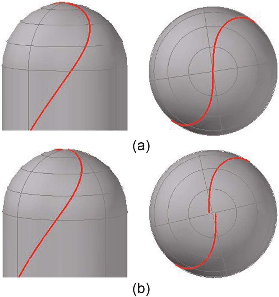
Model result of S-shaped edge curve: (a) S-shaped edge curve without tooth offset center and (b) S-shaped edge curve with tooth offset center.
Grinding algorithm of the rake face of ball-end milling cutter
Because of the fact that the ball-end milling cutter has complicated space curve and surface, the key problem of manufacturing is how to change it as a geometrical problem to control machine tool moving. Based on the geometrical model of S-shaped edge curve of the ball-end milling cutter, the characteristic of the rake face of the ball-end milling cutter with constant normal rake angle is analyzed, the tangential and normal vectors of the rake face are deduced, and then position and orientation of the grinding wheel are resolved when the rake face is machined.
There are two main methods of grinding the rake face of ball-end milling cutter with grinding wheel:
Using the external conical surface of grinding wheel to machine;
Using the end face of grinding wheel to machine.
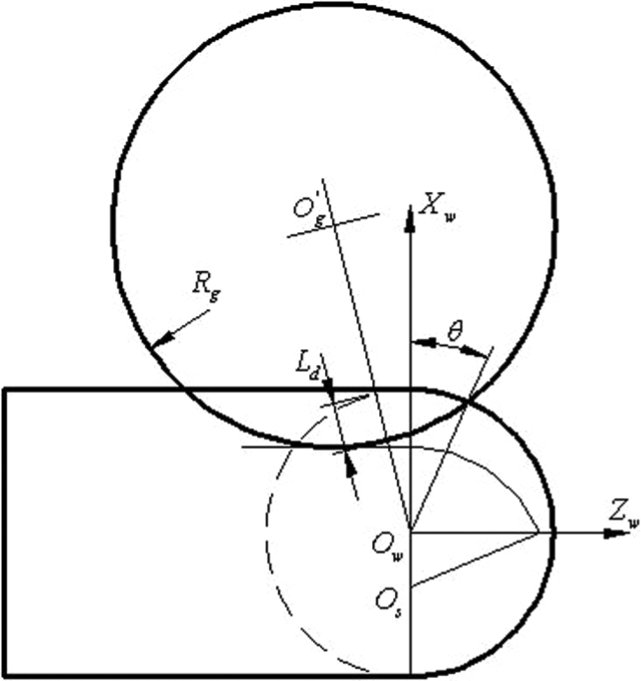
Here gives the grinding algorithm which uses the end face of grinding wheel for grinding the rake face of ball-end milling cutter. The rg (position vector) of Osg (the center of big end circle of grinding wheel) and T (axial vector of the grinding wheel) are used to express the motion curve of the grinding wheel with arbitrary instantaneous processing, as shown in Figure 4. In the grinding process, the contour of the big end circle of the grinding wheel is tangent to the edge curve of the ball-end milling cutter to the point M and through controlling the Ld (cutting depth of wheel) and angle of swing to make sure the position and orientation of the grinding wheel.
Definition and calculation of cutting depth
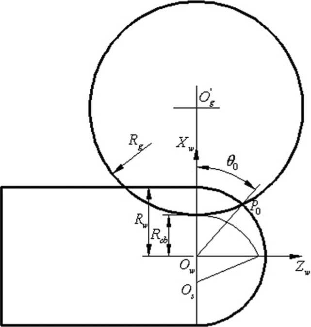
To improve the strength of ball end of the S-shaped edge, for most ball-end milling cutters, it requires that the depth of chip-breaker-groove of the end cutting edge is more close to the ball end. So, here a theoretical curve in the slot bottom is defined, which is used to control cutting depth of the grinding wheel in the grinding process, as shown in Figure 7.
Processing methods of the rake face of ball end.
The curve is circular arc, the center of circle is Os and the radius is Rs. If Rcb (the radius of initial core circle) and h (minimal adjustment quantity of ball end) are known, then

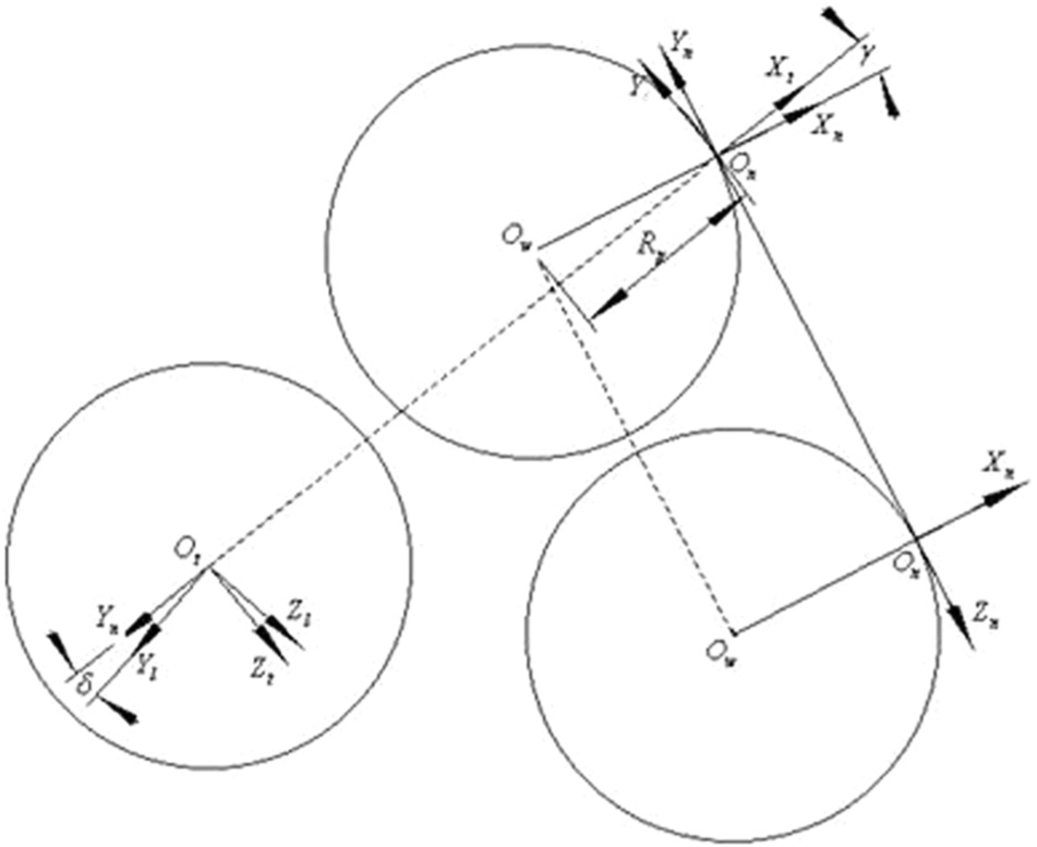
The equation only describes the curve of the slot bottom as a theoretical plane curve. But the curve is space curve in actual machining process, and the big end circle of wheel is located at the XnZn plane of O-XnYnZn (coordinate system of normal section), and to avoid the grinding wheel interfere with the edge curve, which was machined, the big end circle of the grinding wheel has an inclined angle and an angle of minute regulation in the grinding process. Therefore, the plane of the big end circle of the grinding wheel maybe does not pass through the center of sphere, as shown in Figure 8. So, according to the planar curve of the slot bottom, the theoretical cutting depth can be resolved, and the position and orientation of the grinding wheel with the cutting depth will be obtained. In the grinding process, the contour of the big end circle of the grinding wheel is tangent to the edge curve of the ball-end milling cutter to the point M, and the grinding wheel is tangent to curve of bottom of slot to the point M1, as shown in Figure 9; the cutting depth of the grinding wheel is defined as a line segment between Og (center of big end circle) and Ow (center of sphere), which exists in the intersecting part of big end circle of the grinding wheel and section of ball end.
Curve in the bottom of chip pocket.
Schematic diagram of cutting depth.
According to the laws of cosine and sine, the length of the line is derived


And then, the coordinates of central point of the big end circle of the grinding wheel are also obtained

Finally, the cutting depth of the grinding wheel is

But in actual machining process, to ensure the smooth connection of the rake face of the ball end and the rake face of the circumferential tooth, when the grinding wheel is initial cutting, the cutting depth in the Xw direction is consistent with the slot depth of the circumferential tooth, so the above-mentioned equation to get the cutting depth of the grinding wheel is not suitable. Therefore, the critical angle of complete cut and incomplete cut of the grinding wheel is

When θ < θ0, as shown in Figures 10 and 11, in the workpiece coordinate system

And the coordinates of center of the big end circle of wheel is

The cutting depth of any point is
Cutting depth in dividing point.
Cutting depth before dividing point.
Solution of position and orientation of grinding wheel
The position and orientation of wheel are derived in the following two steps:
First, put the big end circle of wheel on the normal section coordinate system of plane XnZn to ensure certain rake angle, and based on the O-XnYnZn, rotate an angle γ along Zn-axis to get the transitional coordinate system Ot-XtYtZ. In this case, the big end circle of wheel is on the plane XtZt of Ot-XtYtZt.
To avoid interference, based on Ot-XtYtZt, rotate a minimal angle
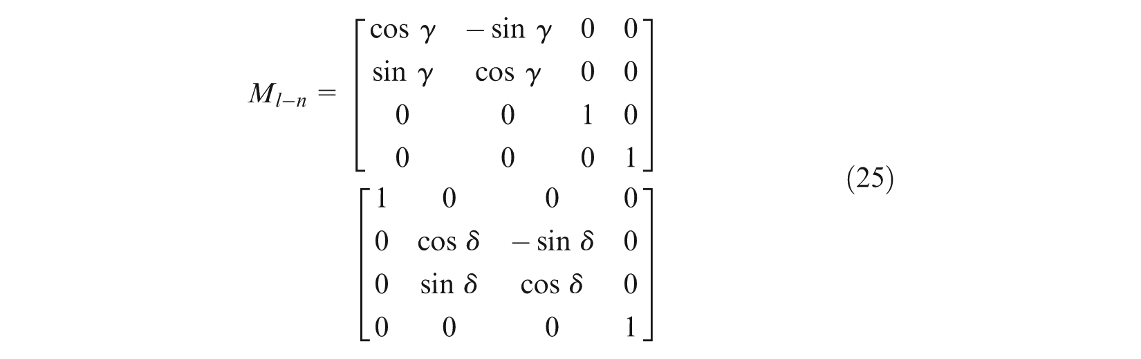
The relationship of the grinding wheel coordinate system and the local coordinate system Ol-XlYlZl is shown in Figures 12 and 13; Xg- and Yg-axes of the wheel coordinate system are parallel to the Z1- and X1-axes of the local coordinate system, so the transformation matrix from the wheel coordinate system to the local coordinate system can also be obtained

And then, the transformation matrix from the grinding wheel coordinate system to normal section coordinate system is
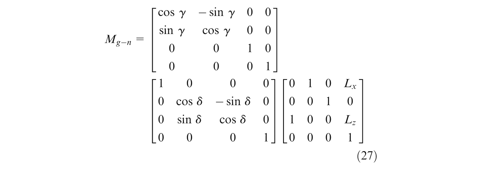
So, the transformation matrix from the grinding wheel coordinate system to workpiece coordinate system is

Coordinate transformation in the rake face of ball end.
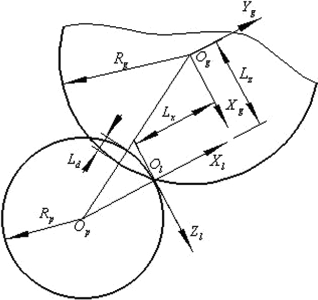
Location of the wheel in the local coordinate system.
In the local coordinate system Ol-XlYlZl, the coordinates of center of the big end circle of the grinding wheel is

And then

When θ≤θ0, substituting equation (21) we get

When θ > θ0, substituting equation (20) into equation (30) we get

In the grinding wheel coordinate system Og-XgYgZg, the direction of axis vector of the grinding wheel is Fg = {0, 0, 1}, and the coordinates of center of the big end circle of wheel are Pg = {0, 0, 0}. Substituting that into equation (27), we can get the direction of axis vector of the grinding wheel and the coordinates of cutter location point.
3D design and machining experiment of ball-end milling cutter
3D design of ball-end milling cutter
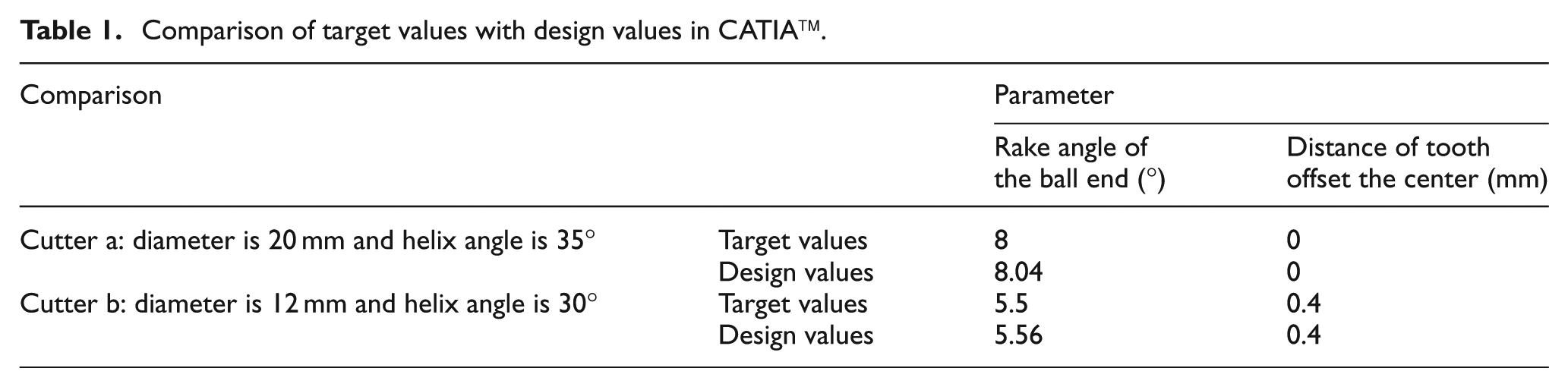
In order to verify the model of the S-shaped edge of the ball-end milling cutter, a 3D design and interactive simulation software are developed using C ++-based CAA and Basic-based VBA of CATIA. A design example is used to check the mathematical models with the following design parameters, as shown in Table 1. The 3D solid model of the ball-end milling cutter with various features is shown in Figure 14. Here, two cutters are listed, one is ∅20 mm cutter (cutter a) with tooth over center (h = 0), and the other is ∅12 mm cutter (cutter b) with tooth offset center (h = 0.4). The measured parameter values (design values and target values) are listed in the following (Table 1), which are very close to the expected design values. Because the structure of ball-end milling cutter is complex, the measured results are not completely equal with the target values due to the influence of the measuring position and measurement precision. The results have met the design requirement.
Comparison of target values with design values in CATIA™
3D solid model of the ball-end milling cutter: (a) cutter a and (b) cutter b.
Grinding simulation and grinding experiment of ball-end milling cutter
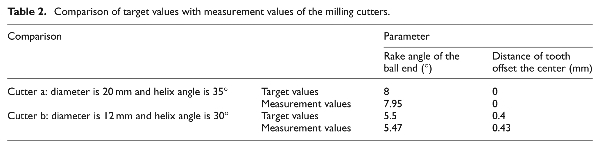
Based on the mathematical models of the ball-end milling cutter, the grinding wheel paths in grinding of the tested two ball-end cutters are calculated, and NC codes are generated by post-process, which would be transferred into VERICUT for 3D grinding simulation, as shown in Figure 15. The tool grinding machine used to machine the cutters is Saacke UW1F. Figure 16 shows the machined cutter, in which “cutter a” is the ball-end milling cutter with teeth over center and “cutter b” is the cutter with tooth offset center. The measurement of the given parameters shows that the performance of this ball-end milling cutter meets the design requirements. The measured parameter values (design values and target values) are listed in Table 2, and they are in agreement with the target values.
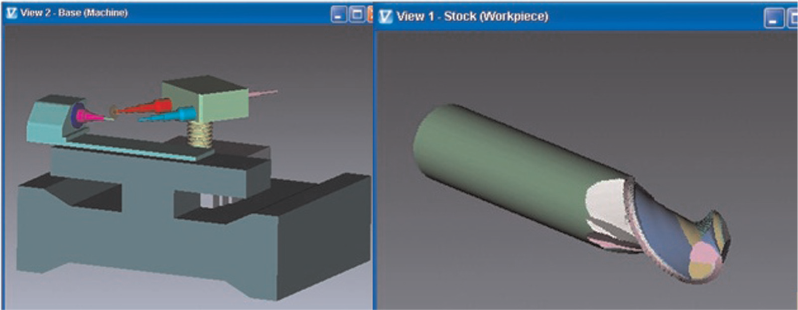
Grinding simulation of ball-end milling cutter.
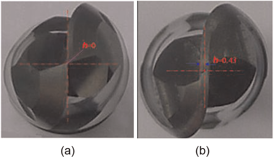
Sample of the milling cutters machined using the developed software: (a) cutter a and (b) cutter b.
Comparison of target values with measurement values of the milling cutters.
Conclusion
In this study, a mathematical modeling method of the S-shaped edge curve and grinding algorithm of rake face on the ball end are presented. The edge curve acquired based on this mathematical model has a good S-shape and can connect with the circumferential edge curve smoothly. Furthermore, the model can be used easily to establish the S-shaped edge curve with tooth offset center or without tooth offset center by controlling the value of the tooth offset center. With the support of the accurate mathematical model, a grinding algorithm of rake face on the ball end is studied. The machining simulation and the grinding experiments verified the feasibility and availability of the new modeling methods and the grinding algorithm.
Footnotes
Appendix 1
Declaration of conflicting interests
The authors declare that there is no conflict of interest.
Funding
This work was supported by Fundamental Research Funds for the Central Universities (No. SWJTU11CX0144), Program for New Century Excellent Talents in University (No. 09-0665) and Sichuan Applied Basic Research Plan (2012JY0092), China.