
Abstract
A chamfering method is proposed in order to improve processing accuracy and efficiency of tooth crest chamfering of spiral bevel gear. Coordinates of discrete points of upper and lower edges of chamfering surface are calculated based on the mathematical model of tooth surface and face cone. Distances between center of ball end milling cutter and upper and lower edges are set equal to radius of the ball end milling cutter, chamfering tool path is generated by particle swarm algorithm solving, both sides of tooth crest can be chamfered simultaneously to ensure processing efficiency. Direction angle of the cutter axis is calculated based on the relationship between direction of the cutter axis and contact positions of the cutter surface. Aiming to prolong service life of cutter, direction angle varies uniformly within the feasible region and contact positions distribute evenly on the cutter surface. Pinion without tooth crest chamfering is installed on four-axis CNC machine tools, edge detector is used to detect axial and circumferential cutter positions, then chamfering experiment is completed. Widths of chamfering surface are measured on different measuring positions, maximum error is 0.08 mm compared with design width 1 mm which appears at tooth crest inner end of convex side. Measuring results show that chamfering error is much smaller than that with manual chamfering, which indicates that the chamfering method is feasible.
Introduction
After machining process of spiral bevel gear is completed, acute edges are formed at the junction of conjugated tooth surface and face cone.1,2 Due to machining error of tooth surface and mounting error of gear pair, 3 tooth roots of gear and pinion are scratched by tooth crests of pinion and gear in meshing process, which causes running noise 4 and reduction of service life, 5 therefore it is necessary to perform tooth crest chamfering.
Some researchers had studied gear chamfering problem. Guo et al. 6 proposed an equipment adjusting parameter calculation algorithm, which can improve accuracy and practicability for gear camber chamfering. Wang et al. 7 established a gear chamfering model based on cone grinding wheel and proposed a calculation method of chamfering surface size. Liu 8 proposed a chamfering miller design principle and calculation method for kinetic relationship between gear and the miller. Karl-Martin 9 proposed a tooth crest chamfering method realized with a multi-tooth cutter.
Spiral bevel gear has an irregular shape comparing with spur gear, helical gear and spur bevel gear, which causes more difficult to perform tooth crest chamfering. A few researchers had studied some tooth crest chamfering methods of spiral bevel gear. Xu et al. 10 proposed a tooth crest chamfering method based on cone type grinding wheel and computer simulation was completed using VERICUT software, but this chamfering method was only applicable to formation spiral bevel gear. Han et al. 11 applied a special cutter to perform chamfering of formation spiral bevel gear, concave and convex sides of tooth crest were unable to process simultaneously, which led to low processing efficiency. Li et al. 12 applied a rotational indexing-chamfering method to process tooth crest of extended epicycloid gear, concave and convex sides of tooth crest can be processed simultaneously in theory, but this chamfering method can not be realized on existing machine tools which led to poor practicality. Every chamfering method mentioned above is only applicable to a particular type of spiral bevel gear, whose processing feasibility is difficult to judge because of lacking experiment.
General CNC machine tools are divided into three-axis, four-axis and five-axis CNC machine tools.13,14 Three-axis CNC machine tools can only perform three mutually perpendicular motions, when pitch angle of spiral bevel gear is relatively small, interference between gear and cutter appears at the tooth crest of convex side, therefore tooth crest chamfering on three-axis CNC machine tools is only applicable to spiral bevel gear with relatively large pitch angle. Five-axis CNC machine tools consists of three linear motions and two rotational motions, 15 tooth crest chamfering can be realized on gear with any value of pitch angle, but purchase cost of five-axis CNC machine tools is high which causes poor processing economy. Four-axis CNC machine tools consists of three linear motions and one rotational motions which is much cheaper than five-axis CNC machine tools, interference can be avoided and indexing can be realized by rotation motion of four-axis CNC machine tools, therefore it is suitable to perform tooth crest chamfering on four-axis CNC machine tools. Ball end milling cutter is widely used in NC machining due to its low preparation cost and high flexibility,16,17 which is applicable for processing complex curved shape. 18 According to the analysis above, a tooth crest chamfering is proposed based on four-axis CNC machine tools and ball end milling cutter, which can meet requirements of high processing efficiency and low processing cost.
Mathematical model of tooth surface
Machine tools coordinate system
Tooth crest chamfering is researched by taking Gleason left-hand modified roll pinion19,20 as an example. Machine tools coordinate system of pinion processing is shown in Figure 1. Intersection point of top plane of cutter and axis of generating gear is defined as origin Om. The direction from cutter holder to cutter tip is defined as Zm, the straight up direction is defined as Ym, the direction of Xm is determined by the right hand rule. O0 is the intersection point of top plane and axis of cutter, the length of O0Om is called radial setting S1, the angle between O0Om and Xm is called cradle angle
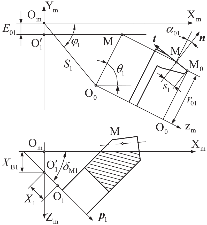
Machine tools coordinate system of pinion processing.
Homogeneous transformation matrices
If pinion processing of modified roll method is realized by a mechanical modified roll mechanism, suppose that angular velocity is 1 when modified roll mechanism is inactive, after modified roll mechanism is activated, cradle angle

where

If pinion processing of modified roll method is realized by CNC spiral bevel gear tooth machine tools, equations of
In cutter coordinate system, the locus

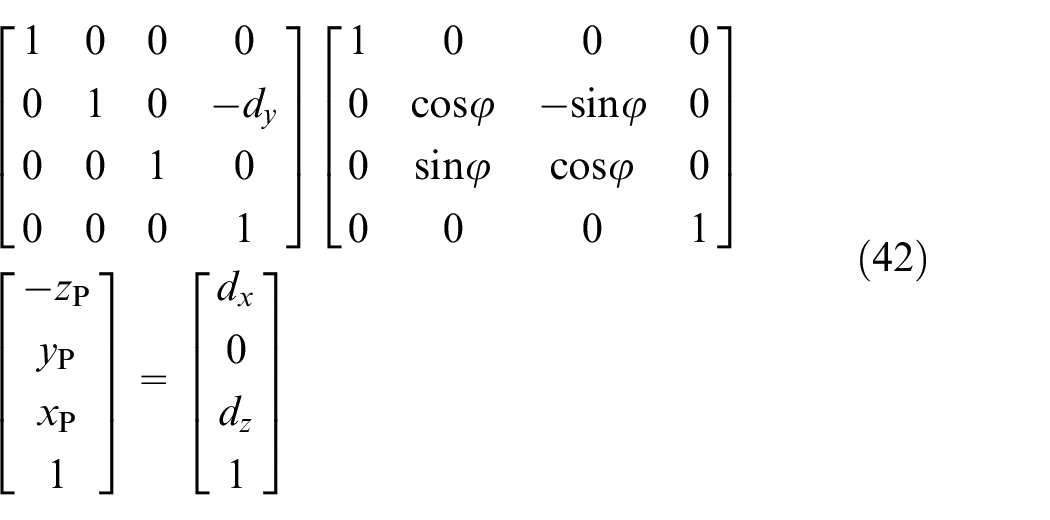
When cutter is moving, homogeneous transformation matrix of cutter coordinate system in machine tools coordinate system is expressed as
When blank reaches the position of machine tools settings, homogeneous transformation matrix of blank in machine tools coordinate system is expressed as
Homogeneous transformation matrix of pinion rotation is expressed as

Relative velocity of the locus

Suppose that

When the variable

Coordinates calculation of discrete points on tooth crest line
Discrete points planning on axial section
An irregular quadrilateral ABCD is obtained when tooth surface is projected to axial section, tooth crest line corresponds to face line, as shown in Figure 2. Two endpoints of face line is denoted by A and B, whose coordinates are written as

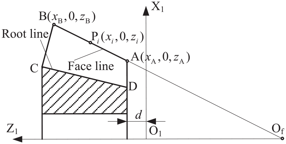
Discrete points of face line on axial section.
Discrete points on tooth crest line
A circle is formed when point
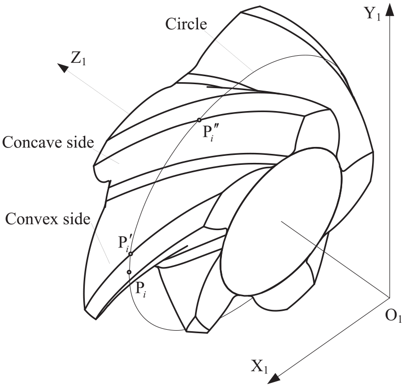
Discrete points on tooth crest line.

Let the coordinates of a point of tooth surface of convex side be

This problem is solved by particle swarm algorithm, number of particles is set to 50, number of iterations is set to 10,000, solving convergence condition is
When subscript value i varies from 1 to m, discrete points on tooth crest line of convex side are calculated in turn, then discrete points on tooth crest line of concave side are calculated by the same way.
Tangent vectors of discrete points
Point

Let

Unit tangent vectors of discrete point.
Upper and lower edges calculation for chamfering
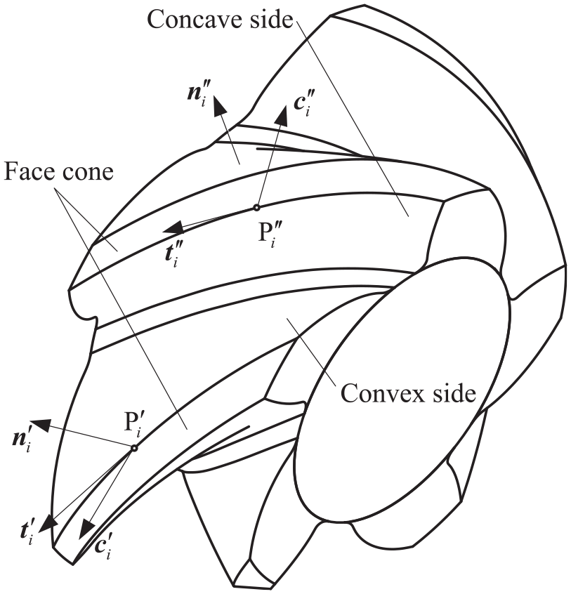
Auxiliary circles for edges calculating
Let the plane through
Auxiliary circles.
Let the intersection of


Coordinates of points
Intersection calculating of auxiliary circle and tooth surface
A circle is formed when point
This problem is solved by particle swarm algorithm, algorithm parameters are as same as above.
After coordinates of point
Intersection calculating of auxiliary circle and tooth surface of convex side.
The coordinates of point
This problem is solved by adopting gold-segmentation algorithm, solving convergence condition is
The coordinates of point
Intersection calculating of auxiliary circle and face cone
The coordinates of point

The problem of solving

This problem is solved by particle swarm algorithm, algorithm parameters are as same as above. The coordinates of point
Radius adjustment of auxiliary circle
When subscript value i varies from 1 to m, points
Upper and lower edges.
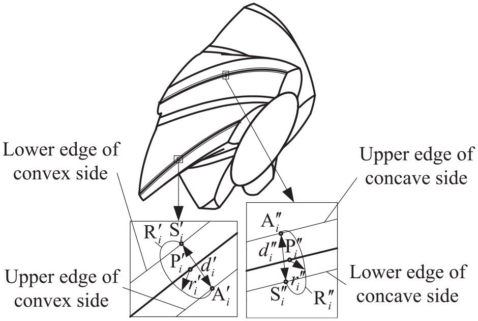
Let the distance between

Initial value of
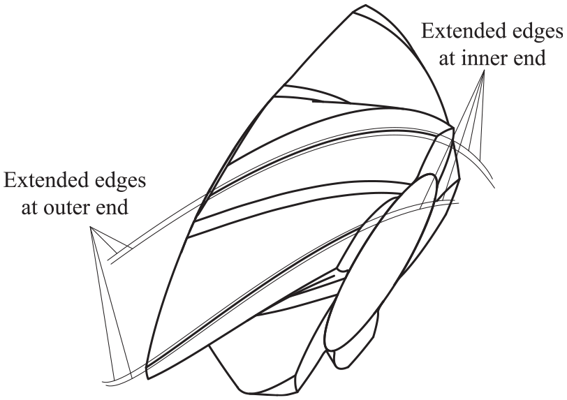
In order to ensure integrity of tooth crest chamfering, edges are extended over inner end and outer end along tooth width direction, it is realized by extending tooth width at inner and outer end when mathematical model of tooth surface is established. Extended upper and lower edges are shown in Figure 8.
Extended upper and lower edges.
Chamfering tool path
Chamfering tool path for both sides chamfering phase
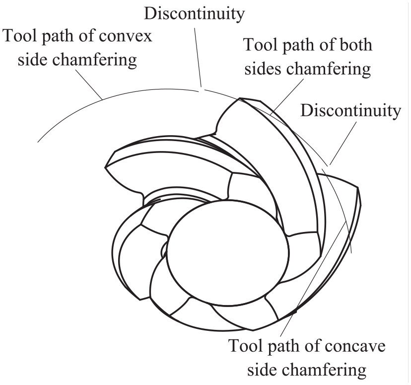
Due to the spatial asymmetry of convex and concave side, when cutter moves from inner end to outer end, chamfering process is divided into three phases in the sequence of concave side, both sides and convex side. In order to process tooth crest chamfering surface accurately, cutter surface should contact with specific edges in different phase of chamfering process. In concave side chamfering phase, cutter surface contacts with upper edge and lower edge of concave side. Similarly, in convex side chamfering phase, cutter surface contacts with upper edge and lower edge of convex side. In both sides chamfering phase, cutter surface contacts with upper edges of concave side and convex side in order to ensure chamfering accuracy of both sides chamfering. Although chamfering dimension errors are inevitable to lower edges of concave side and convex side in both sides chamfering phase, cutter radius can be adjusted to minimize chamfering dimension errors.
Tool path calculation method of both sides chamfering phase is calculated by taking cutter center as reference point. Cutter radius is denoted by

where


Because
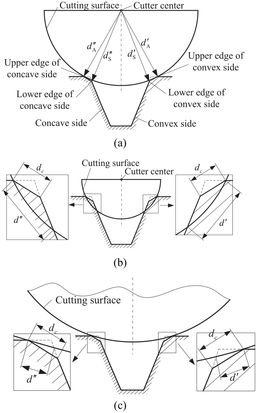
Spatial relationship between cutter surface and edges. (a) When the cutter radius is appropriate. (b) When the cutter radius is too small. (c) When the cutter radius is too large.
If two adjacent discrete points of upper edge of convex side locate on both sides of

k is sequence number of discrete points. Distance between discrete point

When cutter surface contacts with upper edges of convex side and concave side, the cutter position is constrained by

This optimization problem is solved by particle swarm algorithm, number of particles is set to 50, number of iterations is set to 10,000, solving convergence condition is
Both sides chamfering tool path.
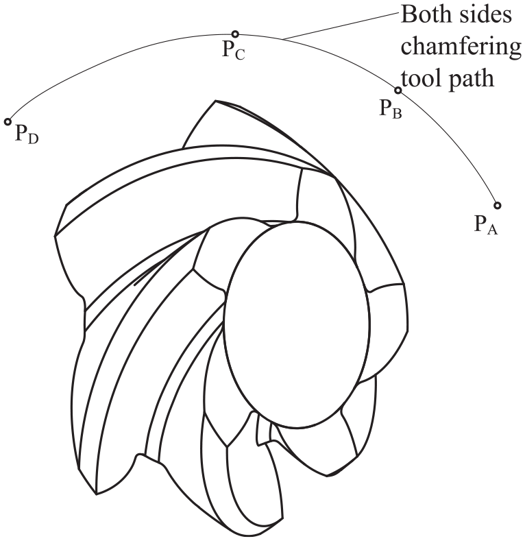
Due to extensions at inner and outer ends along tooth width direction, on both sides chamfering tool path in Figure 10, segment PAPB only performs concave side chamfering in practice, segment PCPD only performs convex side chamfering in practice, segment PBPC performs both sides chamfering. Chamfering dimension error of j-th point of both sides chamfering on lower edges of concave and convex sides are calculated as

Maximum value among

Suppose that cutter surface and upper edge of convex side contact at points of
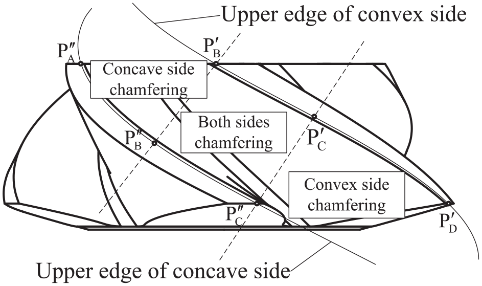
Three phases of chamfering process.
Chamfering tool path for concave side chamfering phase
Segment
This optimization problem is solved by particle swarm algorithm with the same parameters mentioned above.
Suppose that segment
When interference between cutter and tooth crest of convex side does not occur, concave side chamfering is completed according to tool path of concave side chamfering obtained above.
When interference between cutter and tooth crest of convex side occurs, tooth crest of convex side is processed incorrectly. Coordinates of point
Cutter can not approach the region near point
Chamfering tool path for convex side chamfering phase
Segment

This optimization problem is solved by particle swarm algorithm with the same parameters mentioned above. Convex side chamfering tool path is obtained when solving process is completed.
Suppose that segment
When interference between cutter and tooth crest of concave side does not occur, convex side chamfering is completed according to convex side chamfering tool path obtained above.
When interference between cutter and tooth crest of concave side occurs, tooth crest of concave side is processed incorrectly. Coordinate of point
Cutter can not approach the region near point
When solving processes for concave side, both sides and convex side chamfering are completed, integral chamfering tool path for concave side, both sides and convex side is obtained, as shown in Figure 12. There are two discontinuities on borders of three phases, cutter moves up and then moves down in those positions to ensure processing correctly.
Integral chamfering tool path.
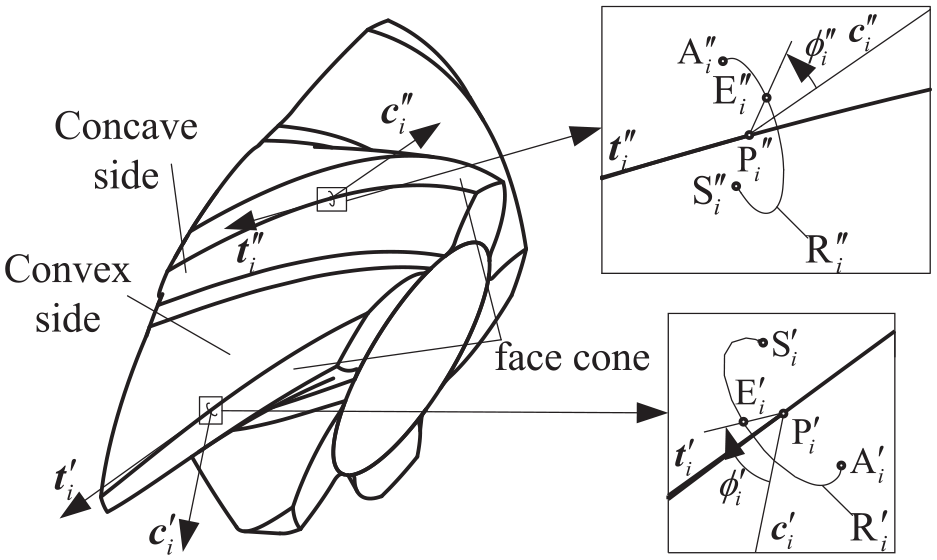
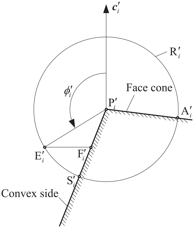
Cutter axis direction calculating
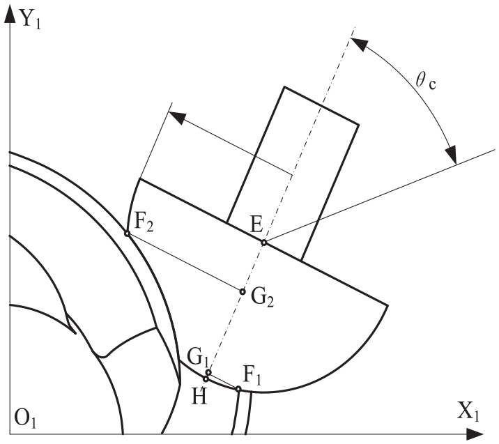
Cutter axis is set to be perpendicular to pinion axis Z1, therefore chamfering can be realized on four-axis CNC machine tools. Cutter center is denoted by point E and cutter axis direction angle is denoted by
Contact positions on cutter surface.
In both sides chamfering phase, suppose that upper edge of convex side and cutter surface contact at point

In concave side chamfering phase, contact point
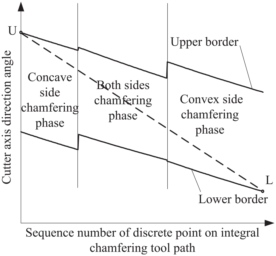
Feasible region of cutter axis direction angle.

p is the number of discrete points on integral chamfering tool path and
NC codes generating
Axial cutter position detecting
Coordinate system of four-axis CNC machine tools is denoted by
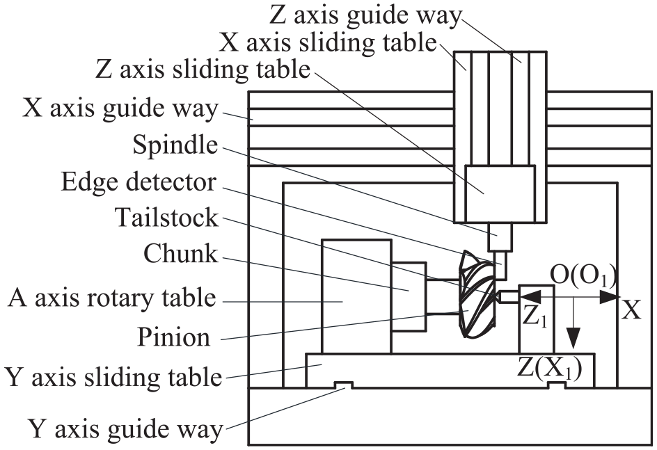
Coordinate systems of pinion and four-axis CNC machine tools.
When axial cutter position detecting is performed, Y axis sliding table moves to make cutter axis and A axis intersect, then the value of Y axis is set to 0 in CNC system. X and Z axis sliding tables move to make edge detector and inner end of pinion contact, the distance between inner end and point O1 is denoted by d in pinion coordinate system shown in Figure 2, then the value of X axis is set to
Circumferential cutter position detecting
When circumferential cutter position detecting is performed, a convex side tooth crest edge is selected as detecting datum. Suppose that pinion is installed on chunk as the position relationship shown in Figure 16, when rotation angle of A axis is kept unchanged, X, Y and Z axis sliding tables move to make edge detector and the convex side tooth crest line contact, the cutter position determined by X, Y and Z axis sliding tables is called circumferential cutter position.
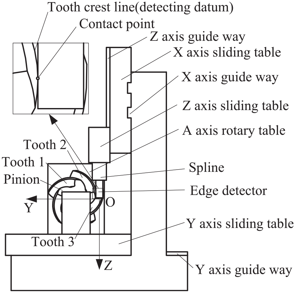
Circumferential cutter position detecting.
Taking the pinion in Figure 16 as an example, if convex side tooth crest line of tooth 1 is chosen as detecting datum, edge detector will contact with conjugated tooth surface of convex side firstly, if convex side tooth crest line of tooth 3 is chosen as detecting datum, edge detector will contact with concave side tooth crest line firstly, two situations above will cause detecting error, so it is suitable to choose convex side tooth crest line of tooth 2 as detecting datum. For any gear, as always there is a suitable convex side tooth crest line for circumferential cutter position detecting.
For the convex side tooth crest line chosen as detecting datum, let coordinates of the i-th discrete point on tooth crest line, upper edge, lower edge be
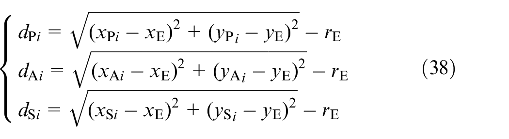
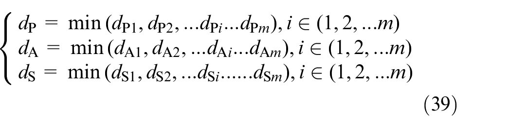
when
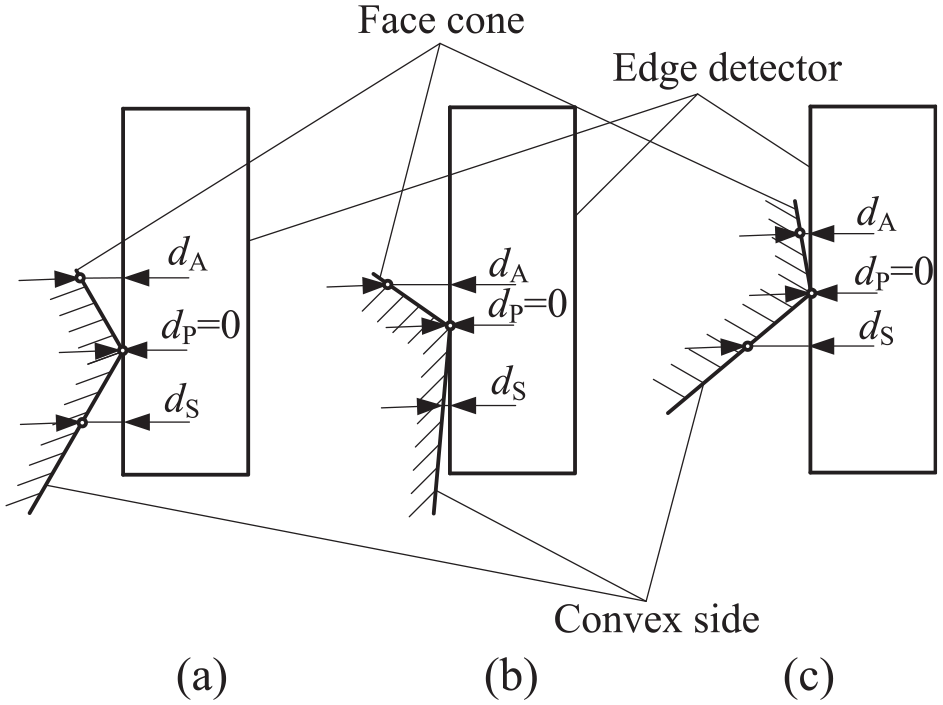
Different contact situations. (a)
Let the coordinates of contact point of edge detector surface and tooth crest line be

Optimal variables are
Pinion without tooth crest chamfering is mounted on four-axis CNC machine tools. The values of X and Z axis are set to
NC codes calculating
Suppose that a point on integral chamfering tool path in pinion coordinate system is denoted by point P whose coordinates and cutter axis unit vector are denoted by
A axis rotation angle is denoted by

Suppose that A axis rotates with
Chamfering experiment
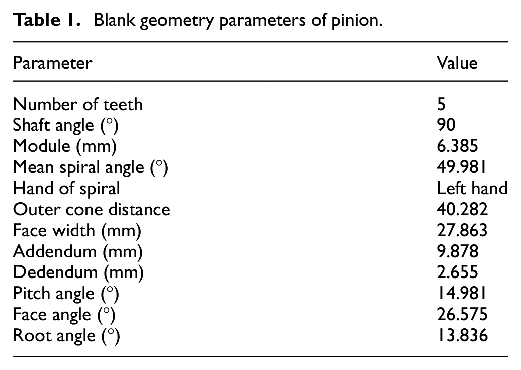
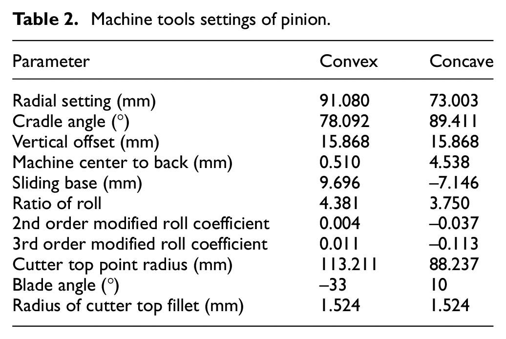
Blank geometry parameters and machine tools settings of pinion are given in Tables 1 and 2.
Blank geometry parameters of pinion.
Machine tools settings of pinion.
Design width of tooth crest chamfering surface is set to 1 mm. m and n are set to 800 and 400 respectively.
Different values of
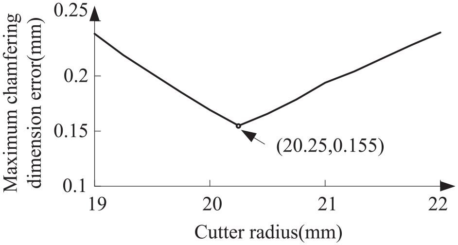
Calculation result of maximum chamfering dimension error.
Cutter radius is set to 20.25 mm, then integral chamfering tool path is obtained which contains 383 discrete points, 1st to 119th discrete points belong to concave side chamfering phase, 120th to 231st discrete points belong to both sides chamfering phase, 232nd to 383rd discrete points belong to convex side chamfering phase. The values of
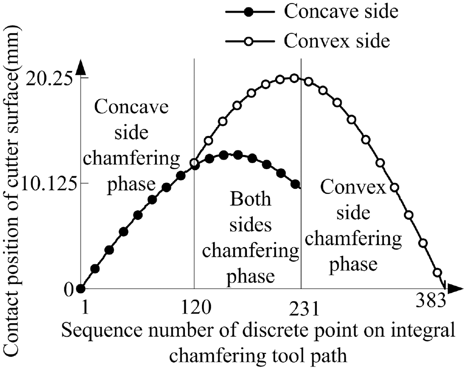
Contact positions of cutter surface.
The material of pinion is nylon PA66, pinion without tooth crest chamfering is mounted on four-axis CNC machine tools, as shown in Figure 20.
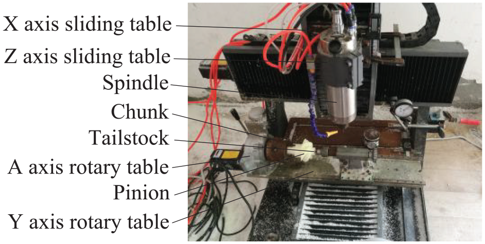
Four-axis CNC machine tools and pinion.
Axial and circumferential cutter position detecting are completed by adopting edge detector, as shown in Figure 21, then edge detector is uninstalled and ball end milling cutter is installed on four-axis CNC machine tools. Because chamfering surface shape has no effect to gear transmission performance and manufacturing tolerance standard of chamfering error has not yet established, it is difficult to judge whether chamfering error is within a tolerable range. Obviously chamfering on CNC machine tools is more efficient than manual chamfering, if chamfering error on CNC machine tools is also smaller than that with manual chamfering, it can be regarded the chamfering method is feasible. Chamfering error relates to many factors, including but not limited to machining error of tooth surface, mounting error of pinion, detecting error, rigidity of cutting tool. The detecting error of edge detector used in this experiment is within 0.01 mm, which is a negligible factor comparing with the other factors, so it is not necessary to use more accurate apparatus for cutter position detecting.
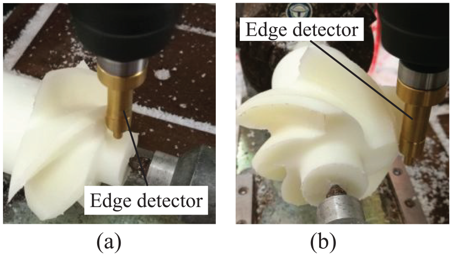
Cutter position detecting. (a) Axial detecting (b) Circumferential detecting.
In order to measure conveniently, a tooth is painted red before tooth crest chamfering, then tooth crest chamfering is completed according to NC codes, as shown in Figure 22.
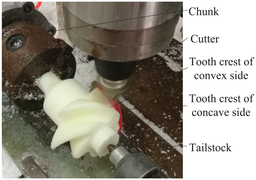
Tooth crest chamfering process.
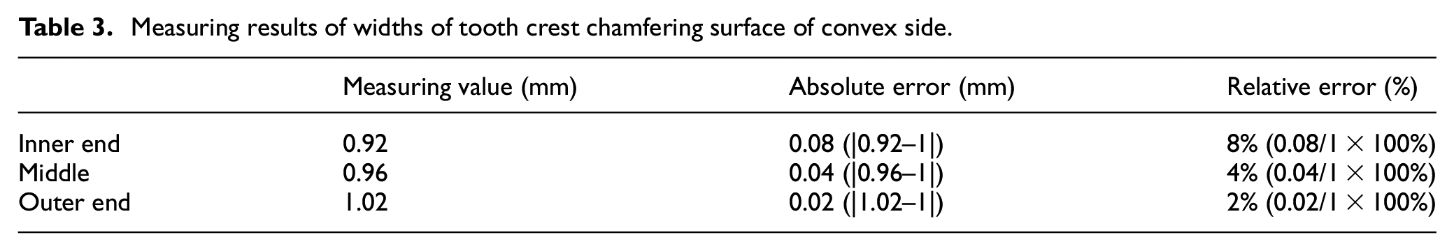
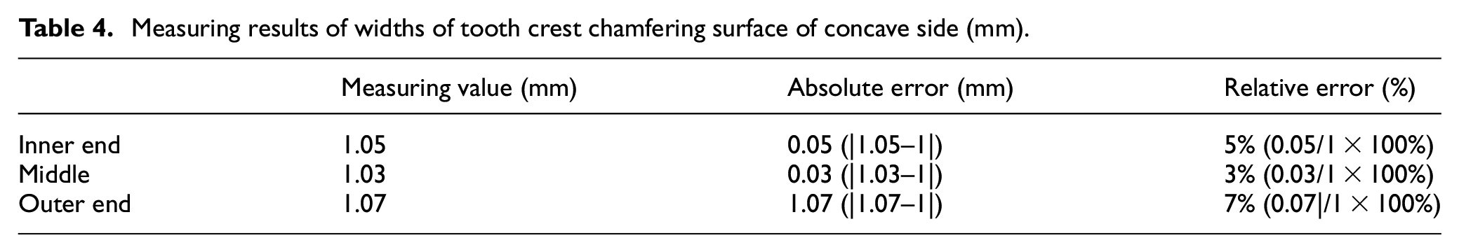
Pinion is uninstalled from four-axis CNC machine tools, widths of tooth crest chamfering surface are measured by vernier caliper on different measuring positions. The measuring positions are inner end, middle and outer end on tooth crest of concave side, similarly three measuring positions locate on tooth crest of convex side. Measuring process on middle tooth crest is shown in Figure 23. Measuring results are shown in Tables 3 and 4, maximum error is 0.08 mm compared with design width 1 mm which appears at tooth crest inner end of convex side, maximum relative error is 8%.
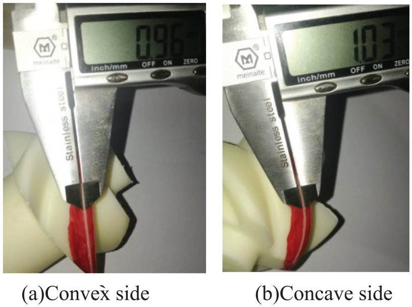
Measuring process of middle tooth crest.
Measuring results of widths of tooth crest chamfering surface of convex side.
Measuring results of widths of tooth crest chamfering surface of concave side (mm).
Conclusion
A chamfering method is proposed in this article, tooth crests of concave and convex sides can be chamfered simultaneously according to tool path, which ensures high processing efficiency. When the cutter axis direction angle varies uniformly in the feasible region, contact positions distribute evenly on cutter surface in chamfering process, which can prolong service life of cutter. Measuring results of widths of tooth crest chamfering surface shows that maximum error is 0.08 mm compared with design width 1 mm which appears at tooth crest inner end of convex side, maximum relative error is 8%. Measuring results show that chamfering error is much smaller than that with manual chamfering, which indicates that the chamfering method is feasible.
If smaller chamfering error is required, machining error of tooth surface, mounting error of pinion, detecting error of cutter position, rigidity of cutting tool should be contained in smaller ranges, which is a general machining error control problem and will not be discussed in this article due to the limited knowledge and ability of the authors.
Footnotes
Appendix
Declaration of conflicting interests
The author(s) declared no potential conflicts of interest with respect to the research, authorship, and/or publication of this article.
Funding
The author(s) disclosed receipt of the following financial support for the research, authorship, and/or publication of this article: This work was financially supported by the Science and Technology Research Project of Hubei Education Department (Grant Number Q20191302) and the Youth Science Foundation of Yangtze University (Grant Number 2015cqn47).