
Abstract
The ability to predict and evaluate the machining performance quickly and realistically is extremely valuable. In this work, experimental investigations were carried out to optimise and compare the machining performance of physical vapour deposition–applied single-layer TiAlN-coated carbide inserts with chemical vapour deposition–applied multi-layer TiCN/Al2O3/TiN-coated carbide inserts during turning of hardened AISI 4340 steel (33-35HRC). The correlations between the performance measures, namely, three components of cutting force, surface roughness and tool life were developed by multiple linear regression models. The correlation coefficients, found almost close to 0.9 for all the developed models, indicate that the developed models are reliable to predict the responses within the domain of the cutting parameters selected. Tool life was observed to be affected more by cutting speed followed by depth of cut and feed. However, this effect was more prominent for physical vapour deposition–coated tools than chemical vapour deposition–coated ones. Optimum cutting conditions were determined using response surface methodology technique and the desirability function approach. It has been observed that while using physical vapour deposition–coated inserts, benefit of availing lower cutting forces and surface roughness with a sizeable tool life can be obtained by using the cutting speed of 176 m/min and at lower values of feed and depth of cut.
Keywords
Introduction
Nowadays, the ability to predict/simulate and evaluate the cutting performance is embedded in the road map for cutting technology. 1 The increasing trend towards maximising productivity with sizeable tool life and desired surface integrity has generated the need for evaluating and optimising the machining performance quickly and realistically. The machining performance of coated inserts depends on several factors, namely, characteristics and properties of the coating layer material(s), substrate used, macro and micro-geometry of the cutting insert, work material properties and cutting conditions employed and so on.
Sufficient work has been reported by various researchers on machining performance of carbide inserts coated with different coatings, and researchers have come up with their own recommendations for the most suitable coating(s) (coated tools) for the given work material combination and cutting condition. Khrais and Lin 2 observed better performance in terms of tool life with physical vapour deposition (PVD)-coated TiAlN inserts by limiting the cutting speed to 260 m/min during turning of AISI 4140 alloy steel under dry cutting condition. Jindal et al.’s 3 experimental investigations showed better performance of PVD-coated TiAlN carbide inserts during turning of different work material combinations and at different cutting conditions in comparison to PVD-coated TiCN and TiN carbide tools. A group of researchers4,5 observed better surface finish with PVD-coated carbide inserts and better tool life with chemical vapour deposition (CVD)-coated thick multi-layer-coated inserts.
Yusuf and Riza 6 developed the first-order and second-order surface roughness models in terms of cutting parameters based on the experimental data during turning with TiN-coated carbide tools. They observed that the feed rate was the main influencing factor on the surface roughness. Anirban et al. 7 investigated the effects of cutting parameters on surface finish and power consumption in high-speed machining of steel using multi-layer TiC/TiN-coated carbide tools. Nalbant et al. 8 investigated the effects of coating method, coating material, cutting speed and feed rate on the surface roughness. From their experimental studies, they developed artificial neural networks (ANN) model, which could be used for prediction of surface roughness.
A good amount of literature is available on the effect of cutting parameters and tool geometry on the machining performance when using coated carbide inserts. Suresh et al. 9 presented the influence of extrinsic factors on machinability of hardened steels, such as variation of cutting forces, chip morphology, tool wear and resulting surface integrity in the machined surface. Noordin et al. 10 investigated the effects of cutting speed, feed and side cutting edge angle of the cutting edge on cutting force and surface roughness while machining with coated carbide tools. They observed feed to be the most significant factor that influences the surface roughness and the cutting force. Cemal et al. 11 observed dissimilar behaviour of PVD-applied single-layer TiAlN- and CVD-applied multi-layer TiCN/Al2O3/TiN-coated carbide inserts in terms of surface roughness against cutting speed.
Ample amount of work has been reported on the optimisation studies during turning. Asilturk and Akkus 12 optimised cutting parameters to minimise surface roughness during turning of hardened steel using coated carbide tools. Aouici et al. 13 optimised cutting parameters for surface roughness and cutting force components during machining of hardened steels using cubic boron nitride (CBN) inserts. Jayakumar et al. 14 optimised machining parameters and reinforcement on the matrix during machining of developed composites using central composite experimental design. Chinchanikar and Choudhury 15 optimised cutting parameters for machining of different levels of workpiece hardness using multi-layer-coated carbide tool. Response surface methodology (RSM) technique and the desirability function approach were used for simultaneously optimising the cutting parameters to minimise cutting forces, surface roughness and for better tool life. In another work, 16 the same researchers have observed lower values of surface roughness and cutting forces for single-layer TiAlN than multi-layer TiCN/Al2O3/TiN-coated carbide inserts. However, the study of analysis concluded that the single-layer-coated inserts are more sensitive to cutting conditions; especially, the cutting speed and the better performance can be achieved by limiting the cutting speed to 200 m/min.
Studies available related to machining performance indicate that PVD-applied single-layer TiAlN-coated carbide inserts produced better surface finish 11 and incurred lower cutting forces 16 and CVD-applied multi-layer MT-TiCN/Al2O3/TiN-coated carbide inserts produced longer tool life.4,5,16 However, from earlier work of the authors, 16 it is understood that the better performance of the PVD-applied single-layer TiAlN-coated carbide inserts can be achieved by limiting the cutting speed to 200 m/min to avoid damages to the machine tool and scrapped components due to catastrophic failure of these tools at higher cutting speeds. Hence, optimisation of the machining performance of these coated inserts considering tool life is extremely valuable.
In this work, experimental investigations were carried out to optimise the machining performance of PVD-applied single-layer TiAlN-coated carbide inserts in view to analyse whether the optimisation studies performed without considering the tool life may give a realistic optimum solution during turning of hardened AISI 4340 steel (33-35HRC). Furthermore, the curves plotted by developing mathematical models based on experimental results for three components of cutting force, surface roughness and tool life when using this insert were compared with the performance curves of CVD-applied multi-layer TiCN/Al2O3/TiN-coated carbide insert plotted using the already developed models from the authors’ earlier published work 15 with a view to investigate the effect of type of tool (type of coating) and cutting parameters on performance measures. The mathematical models were developed by multiple linear regression models, and adequacy of the developed models was checked using analysis of variance (ANOVA) technique. Optimisation study was executed in two different modules using the similar line of approach as discussed by Chinchanikar and Choudhury. 15 The first module determines the optimum cutting condition, which ensures minimum cutting forces and surface roughness based on RSM technique. The second module determines the most optimum cutting condition among the solutions generated in the first module, which gives the maximum tool life using desirability function approach.
Experimental details
Workpiece materials
AISI 4340 low-alloy steel having hardness of 33-35 HRC was used as a workpiece material having a diameter and length of 90 and 400 mm, respectively. AISI 4340 is a heat-treatable low-alloy steel containing alloying metals such as nickel, chromium and molybdenum. This grade of steel is known for its toughness and capability of obtaining high tensile strength in the heat-treated condition while retaining good fatigue strength and adequate ductility. In addition, these high-tensile steels offer excellent corrosion resistance. In the hardened state, this steel is among the difficult-to-machine workpiece materials. AISI 4340 steel finds application in landing gear components, rocket cases and air frame fittings, heavy vehicle crank shafts, connecting rods, spindles, power transmission gears and other structural parts.
Cutting inserts
Experiments were performed using PVD-applied single-layer TiAlN-coated tungsten-based cemented carbide inserts, recommended for a variety of workpiece materials, including most steels, ferritic and martensitic stainless steels and cast irons. 17 The cemented carbide inserts (ISO class P10) having geometry designated by ISO as CNMG 120408 (80° diamond shape with 0.8 mm nose radius) was used for experiments. A right-hand style tool holder designated by ISO as PCBNR 2020K12 was used for mounting the inserts resulted in tool geometry as follows: including angle = 80°, inclination and side rake angles = −6°, clearance angle = 5° and approach angle = 75°. The chip-breaker geometry recommended for medium machining was used for the coated insert designated as −MP. 17
Design of experiments
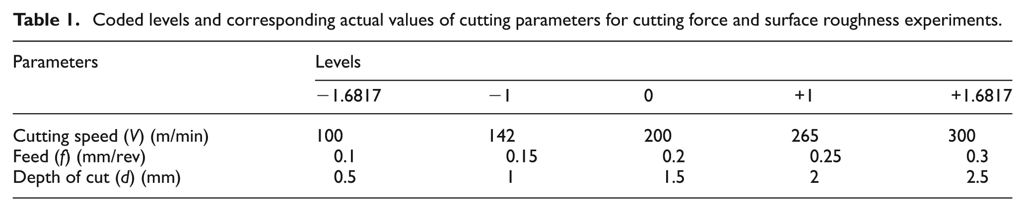
Due to increasing number of laws and directives governing industrial safety and environmental protection, demands for dry or near-dry machining (minimum quantity lubrication (MQL)) with more wear-resistant tool materials are increasing. With this view, in the present work, experiments were carried out varying the cutting speed, feed and depth of cut (DOC) under dry cutting conditions. Central rotatable composite design (CCRD) of experiments with an alpha value of 1.68179 was used for planning of cutting force and surface roughness experiments. 18 Each numerical parameter was varied over five levels: plus and minus alpha (axial points), plus and minus 1 (factorial points) and the centre point. The ranges of three input parameters were decided on the basis of trial experiments, machine capability, literature review and past experience. Coded levels and corresponding actual values of cutting parameters are given in Table 1.
Coded levels and corresponding actual values of cutting parameters for cutting force and surface roughness experiments.
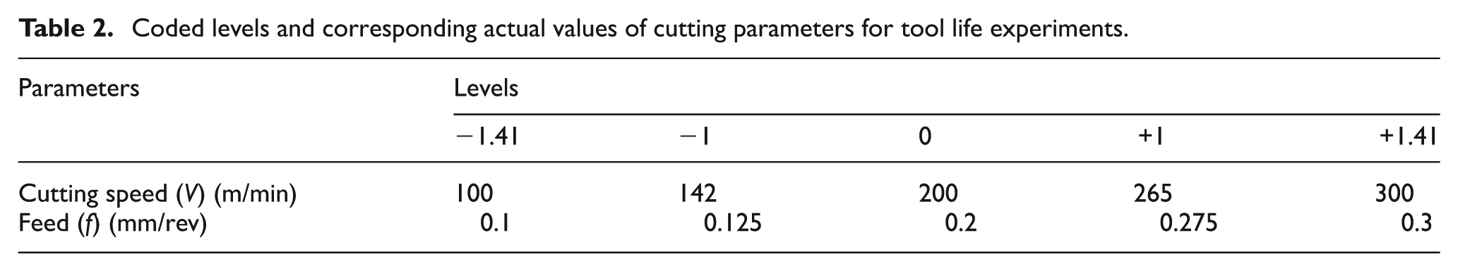
Tool life experiments were also performed according to central composite rotatable design with an alpha value of 1.41, varying the cutting speed and feed in the range of 100–300 m/min and 0.1–0.3 mm/rev, respectively, and at constant DOC of 0.8 mm, as shown in Table 2. However, some additional experiments at different DOCs, one experiment using DOC of 0.5 mm and three experiments using DOC of 1.5 mm, were performed to consider the effect of DOC on tool life.
Coded levels and corresponding actual values of cutting parameters for tool life experiments.
Performing experiments as per design of experiments
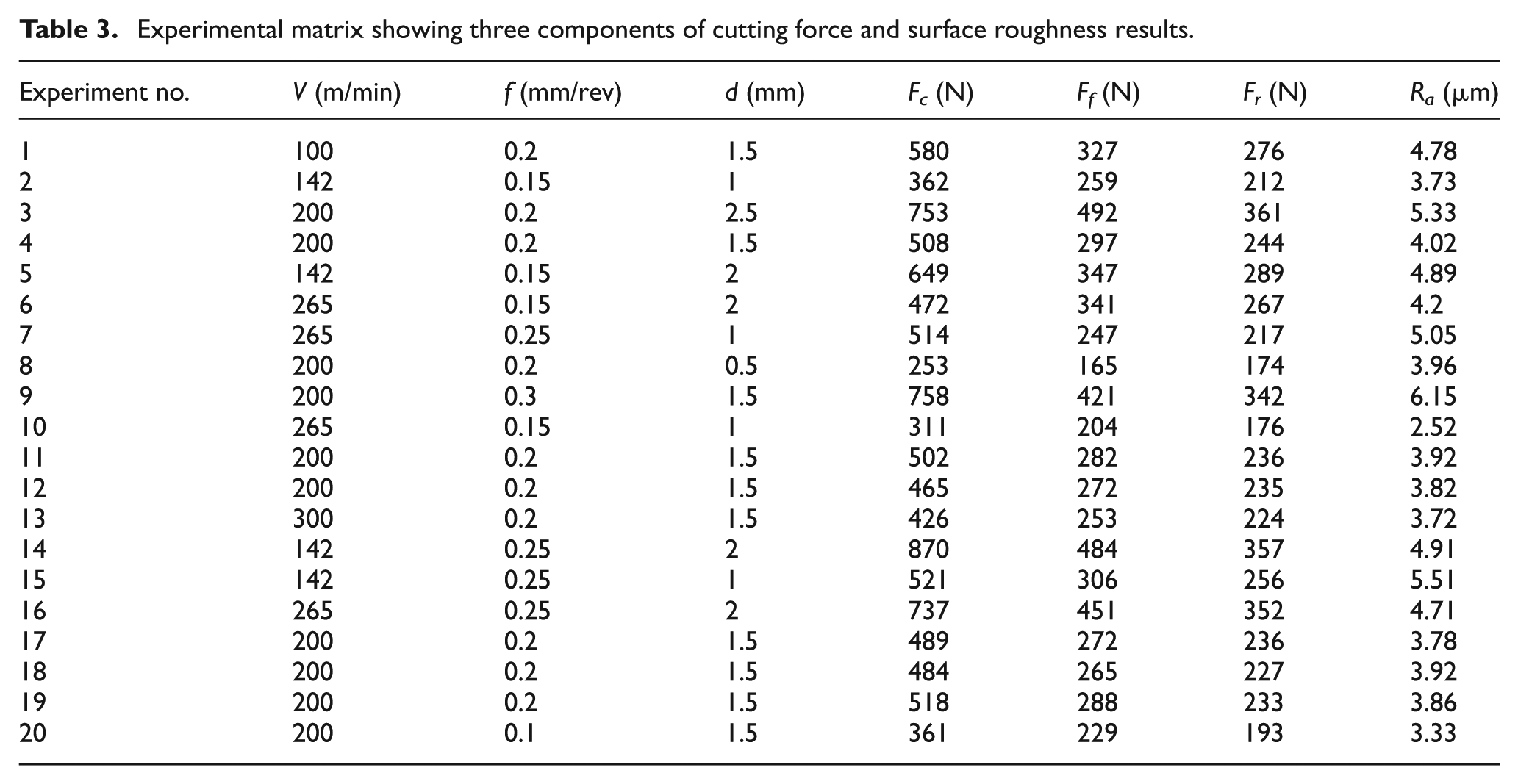
Experiments were carried out on a Hindustan Machine Tools (HMT) make centre lathe under dry cutting conditions. Desired cutting speeds were achieved by using different workpiece diameters and rotational speed available in the machine. During experiments, tool height, its overhang and tool geometry were kept constant. Average values of the cutting force components in a tool in the cutting (Fc), feed (Ff) and radial (Fr) directions were measured by using a three-component piezo-electric dynamometer (KISTLER Type 9257BA) mounted on the cross slide of the lathe, and surface roughness was measured by Qualitest TR100 surface roughness tester and surface roughness contours were obtained by Mitutoyo surface roughness tester, model SJ-301. Digital microscope having magnification of 230X was used to evaluate the wear on flank surfaces. Experimental matrix along with performance measures, namely, three components of cutting forces and surface roughness is shown in Table 3. Experimental results for some of the cutting conditions, especially for cutting forces, are already reported by the present authors in their earlier published work. 16
Experimental matrix showing three components of cutting force and surface roughness results.
Results and discussion
Cutting force and surface roughness models
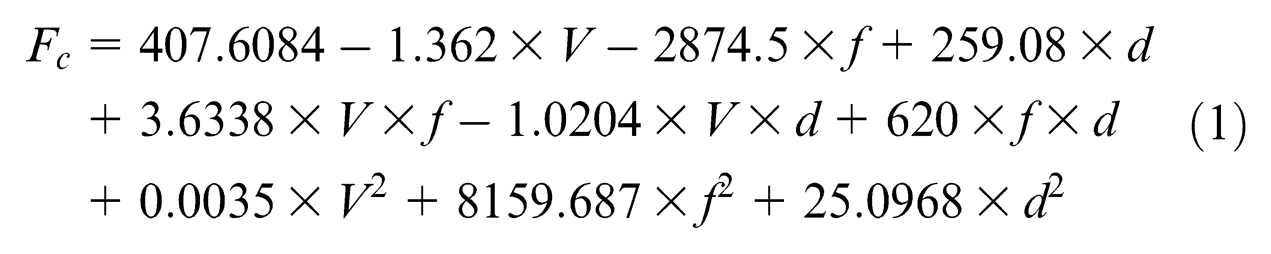
Regression equations for three components of cutting force and surface roughness were developed based on experimental data. The values of the coefficients involved in the equation were calculated by regression method by using the Design Expert software. Equations developed for three components of cutting force and surface roughness are given below.
Cutting force components when using PVD-coated inserts
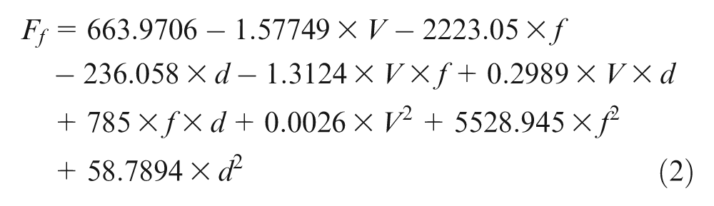
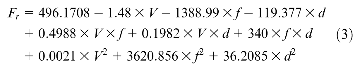
Surface roughness when using PVD-coated inserts
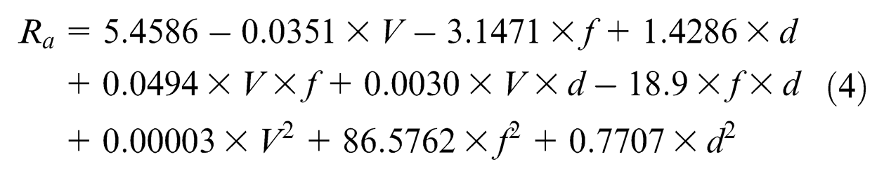
Adequacy of the developed models
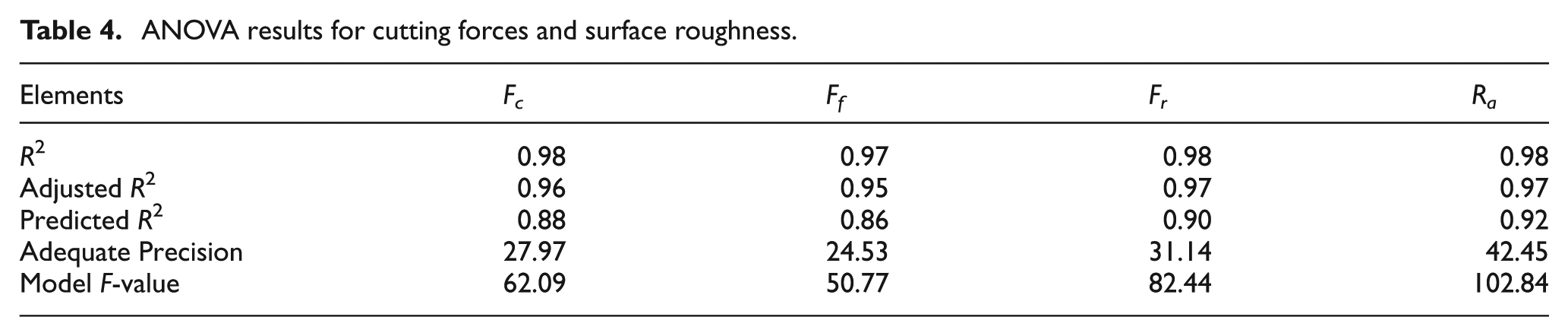
The adequacies of the developed equations were checked by the ANOVA technique. Results of the statistical analysis are depicted in Table 4. It can be seen that the values of R2 (coefficient of multiple determinations, which measures the proportion of variation in the data points) are very close to 1, indicating that the developed equations are significant. The adjusted R2 (a measure of the amount of variation about the mean explained by the model) and predicted R2 (a measure of how good the model predicts a response value) values are within 0.20 of each other, shows that they are in reasonable agreement. Adequate precision (a signal to noise ratio) values are more than 4 as desired, indicating that the developed equations are significant. The model F-values obtained for all the equations also imply that the developed models could be used to predict the responses and hence to support the optimisation studies within the domain of the cutting parameters.
ANOVA results for cutting forces and surface roughness.
Effect of cutting parameters on cutting force components
In order to have the clear understanding of the effect of a given input parameter on the response functions for PVD-applied single-layer TiAlN- and CVD-applied multi-layer TiCN/Al2O3/TiN-coated inserts, namely, three components of cutting force and surface roughness, three-dimensional (3D) surface plots were plotted by varying two of the input parameters and considering value of one of the input parameters at centre point (Table 1). Three-dimensional surface plots for CVD-coated inserts were plotted using the developed models for three components of cutting force and surface roughness from the authors published work. 15 A modified Taylor tool life equation was developed based on the experimental observations, and curves showing tool life were plotted by varying one of the input parameters and keeping the other parameters constant. Finally, cutting parameters were optimised for minimum surface roughness, cutting forces and better tool life for PVD-coated insert.
Figure 1 depicts the 3D surface plots of cutting force components for PVD-coated inserts plotted using equations (1)–(3) and for CVD-coated inserts using the developed models from the authors published work. 15 It can be seen that the PVD-coated inserts incurred lower cutting forces than the CVD-coated inserts. The decrease in cutting force (Fc) with increase in cutting speed is higher for PVD-coated inserts as compared to CVD-coated inserts. In all experiments, after the test, when the insert was examined under the microscope, crater wear was observed for PVD-coated inserts, which was more severe at higher cutting speeds. Crater wear occurs on the rake-face of cutting tools when fast flowing chips adhere to the rake-face resulting in the weakening of the binder due to inter-diffusion of tool and workpiece elements. At higher cutting speeds, higher temperature is generated, and as diffusion is a temperature-dependent process, severe crater wear was observed at higher cutting speeds. However, flank wear as a dominant wear form with absolutely no crater wear was observed when using CVD-coated inserts. 16 The growing crater wear acts as a chip-breaker and aids in breaking the continuous chips resulting in decrease in cutting force when using PVD-coated inserts.
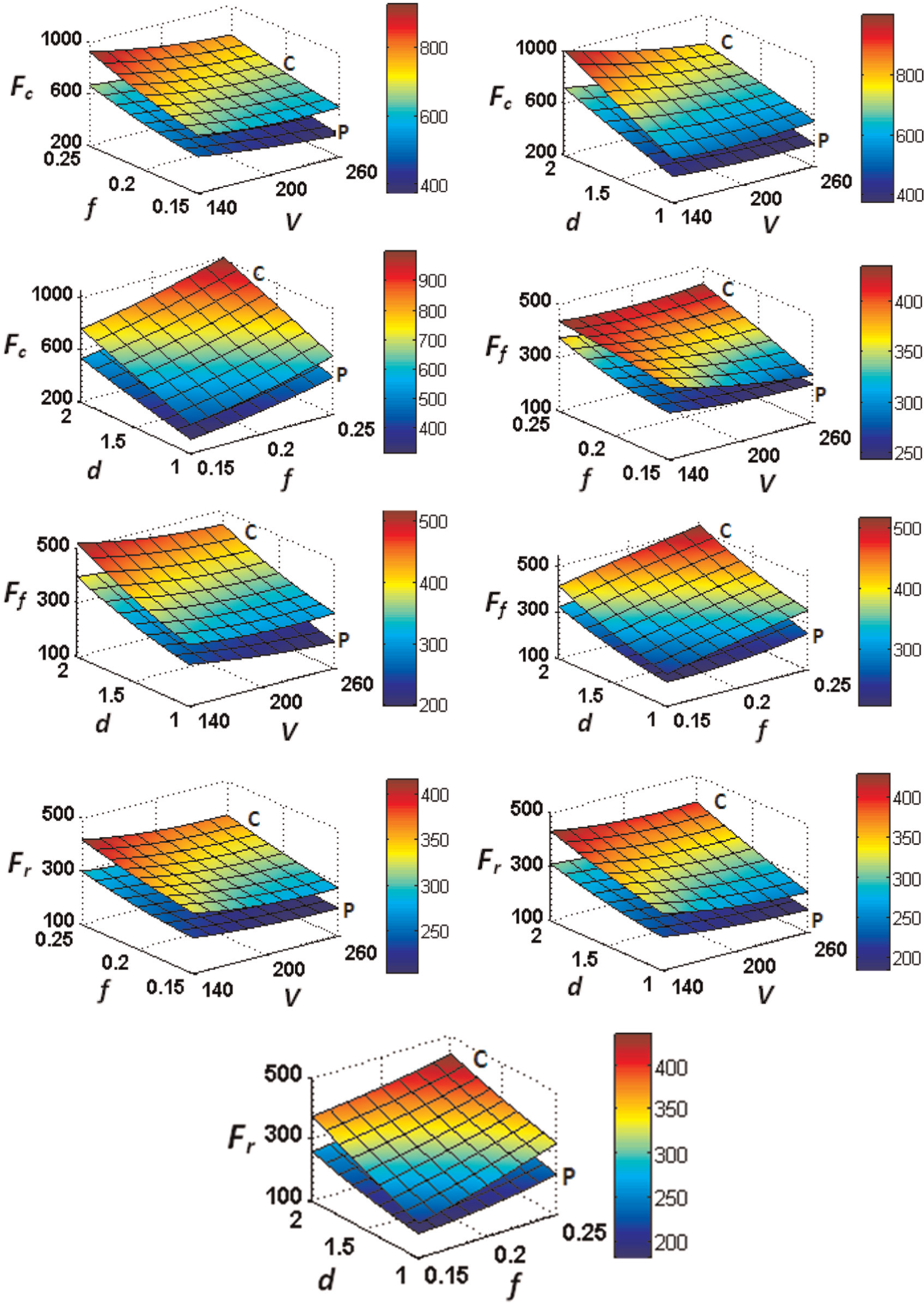
Three-dimensional surface plots showing effect of cutting conditions on cutting, feed and radial forces (letter C and P shows surface plots for CVD-coated and PVD-coated inserts, respectively).
ANOVA results for F-values of cutting force components are shown in Table 5. The factors which were having significant effect on responses are shown by underlined F-values. Similarly, percentage contributions of different elements, obtained by dividing the corresponding element F-value with the total F-value, are given in Table 6. It can be seen that cutting forces get affected mostly by DOC (nearly 60% contribution) followed by feed (nearly 30% contribution), and cutting speed has little influence. However, some of the elements in interaction effects and elements with their higher orders can be seen as significant model terms. Elements V×d having an interaction effect on Fc, when using PVD- and CVD-coated inserts; feed force (Ff) having an interaction effect of f×d, when using PVD-coated inserts and V×f, when using CVD-coated inserts; and radial force (Fr) having an interaction effect of f×d, when using PVD- and CVD-coated inserts can be seen from Figure 1 and Tables 5 and 6.
ANOVA results for f-values of cutting force components and surface roughness.
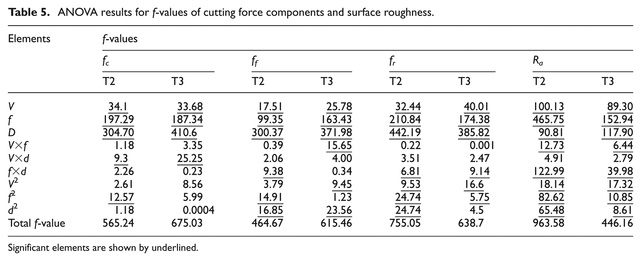
Significant elements are shown by underlined.
Percentage contribution of different elements on cutting force components and surface roughness.
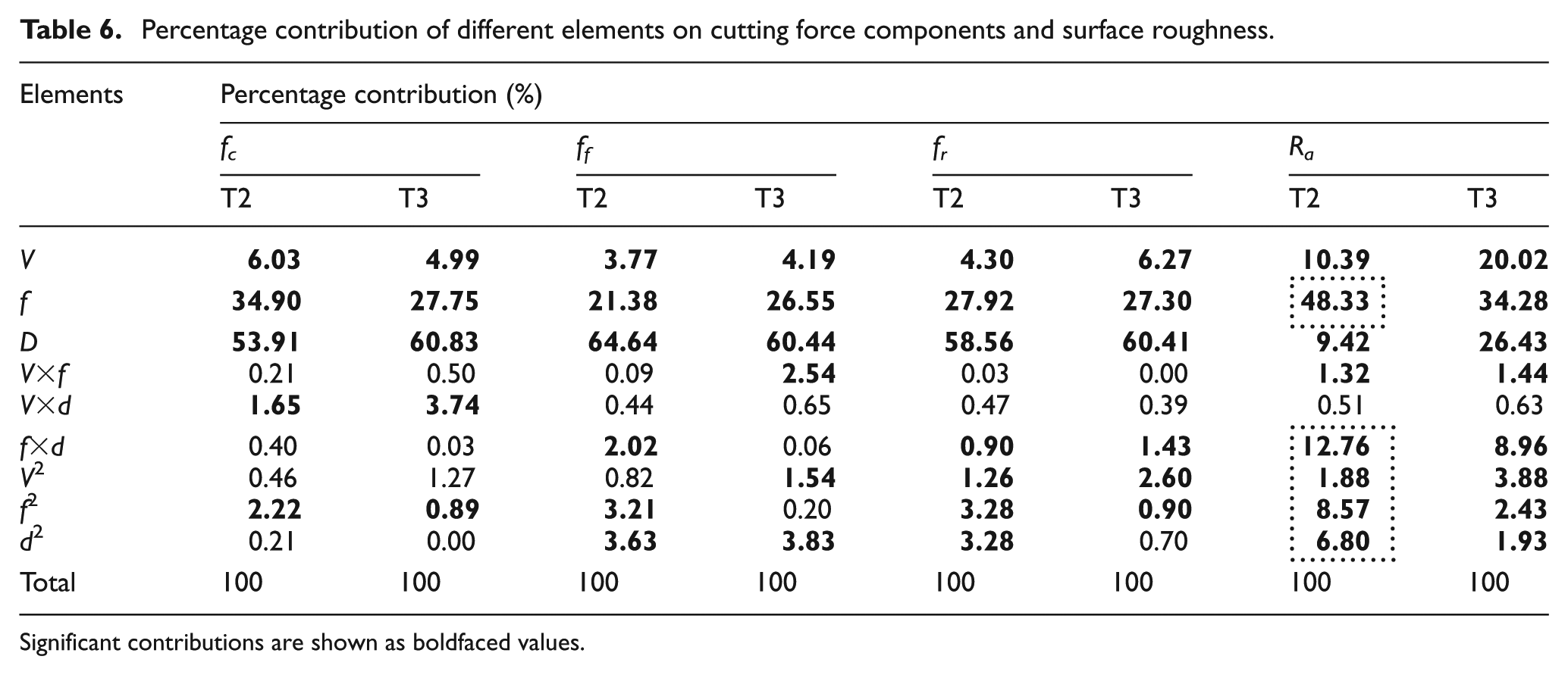
Significant contributions are shown as boldfaced values.
The higher magnitude of force components for CVD-coated inserts in comparison to PVD-coated inserts can be attributed to the fact that the PVD-coated inserts showed a decreasing trend of dynamic force signals because of growing crater wear; average value of the force signal turned out to be lower in magnitude. The difference in the micro-geometry employed for these inserts and the smaller and smoother cutting edge radius of PVD-coated inserts can be seen from the work of Chinchanikar and Choudhury. 16 It can be seen that CVD-coated insert has negative cutting edge style chip-breaker geometry, whereas PVD-coated insert has positive cutting edge style resulting in lower cutting forces. Another reason may be the characteristics of the PVD-applied coating process. Temperatures of about half those used in the CVD process, that is, around 500 °C, are used in the PVD process. The lower processing temperature results in a fine grain, the thermal crack free structure of the coating, very smooth and bright coating surface with a low coefficient of friction between the tool face and the chips, resulting in lower cutting forces. 19
Effect of cutting parameters on surface roughness
Figure 2 depicts the 3D surface plots of surface roughness for PVD-coated inserts plotted using equation (4), and for CVD-coated inserts using the developed surface roughness model from the authors published work. 15 It can be seen that PVD-coated inserts produced lower values of surface roughness. The interaction effects of V×f and f×d on surface roughness is shown in Figure 2(a) and (b), respectively, and in Tables 5 and 6, for both the coated inserts. Decrease in surface roughness with increase in cutting speed and decrease in feed and DOC is shown in Figure 2(a) and (b). It can be seen that interaction effect of f×d is more prominent for PVD-coated inserts, indicating that surface roughness obtained by these tools is more sensitive to cutting conditions, especially feed and DOC. It can be seen that feed and higher orders of feed and DOC (terms shown by dotted rectangle in Table 6) have more significant effect on surface roughness when using PVD-coated inserts in comparison to CVD-coated inserts. The typical surface roughness contours obtained by the roughness tester (Mitutoyo, SJ-301) for PVD- and CVD-coated inserts are shown in Figure 3. More deviations in the surface roughness contour from the mean line are shown for CVD-coated inserts in comparison to PVD-coated inserts. Deviations of the smaller order or lower values of surface roughness in case of PVD-coated inserts resulting due to minimum friction presented by these tools to flowing chips over the rake-face, which can be seen from the work of Chinchanikar and Choudhury. 16
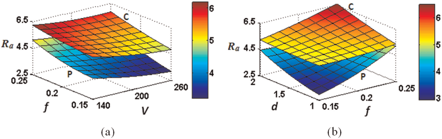
Three-dimensional surface plots showing effect of cutting conditions on surface roughness (a) cutting speed and feed (V x f) for d = 1.5 mm and (b) feed and depth of cut (f x d) for V = 200 m/min (letter C and P shows surface plots for CVD-coated and PVD-coated inserts, respectively).
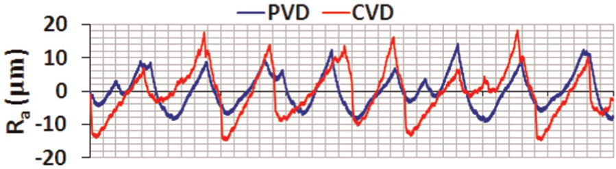
Surface contour plots obtained by PVD- and CVD-coated inserts at V = 200 m/min, f = 0.2 mm/rev and d = 1.5 mm.
Effect of cutting parameters on tool life
Tool life experiments were performed as per the experimental matrix given in Table 7. The tool life criterion used was when the maximum flank wear width or end clearance wear or nose wear reached 0.2 mm, or the occurrence of the catastrophic failure as given in the ISO 3685-1977(E) standard. A tool life model in the form of modified Taylor tool life equation was developed considering the effect of cutting speed, feed and DOC. The authors have already reported tool life observations for some of the cutting conditions of PVD-coated inserts in Chinchanikar and Choudhury. 16 In this work, to develop a tool life model for PVD-coated inserts, some additional experiments were performed at cutting conditions as shown in Table 7.
Experimental matrix for tool life test.
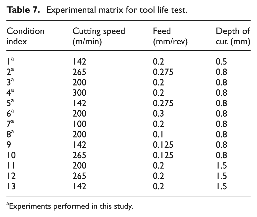
Experiments performed in this study.
Flank wear progressions of PVD-coated inserts at different cutting conditions is shown in Figure 4. A rapid growth in the flank wear which eventually lead to catastrophic failure can be seen for cutting condition index 2 (Table 7). Images of the rake and flank faces of a tool, obtained at different time instants of machining at condition index 2, are shown in Figure 5(a) and (b), respectively. Growing crater wear (images numbered from 1 to 6) and rapid growth of flank wear (tool images numbered 5 and 6) can be seen from these tool images. However, at comparatively lower cutting speed, cutting condition index 7, more or less uniform growth in the flank wear can be seen (Figure 4), indicating that the tool wear, and hence tool life, obtained by these tools is sensitive to cutting conditions selected, and relative influence of each cutting parameter on tool life can be obtained by formulating a model and is discussed in the following paragraph.
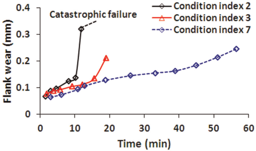
Flank wear progressions of PVD-coated inserts at condition indices 2, 3 and 7.
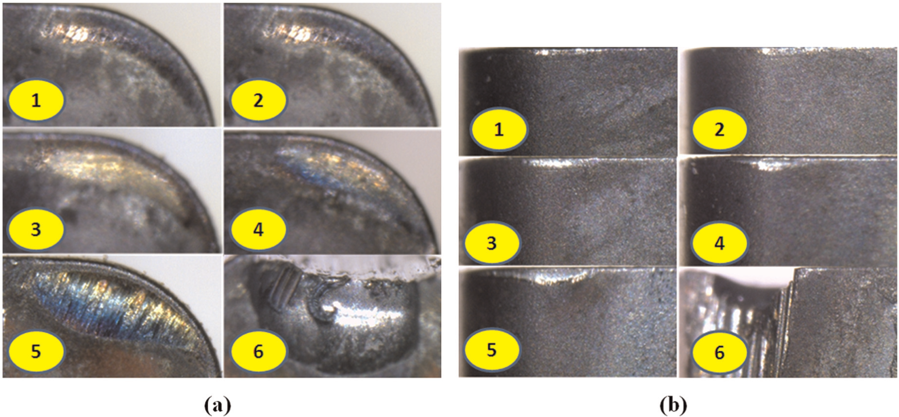
Images of PVD-coated insert at different time instants of machining obtained at condition index 2: (a) rake surface showing growth of crater wear and (b) flank face showing progress of flank wear.
Flank wear progressions of PVD- and CVD-coated inserts at condition index 1 (Table 7) are shown in Figure 6 and also can be seen from the work of Chinchanikar and Choudhury at some of the cutting conditions. 16 Almost in all the cutting conditions investigated, lower flank wear values were observed for PVD-coated inserts in comparison to CVD-coated inserts. However, a sudden increase and domination of the flank wear rate of CVD-coated inserts can be seen. Lower flank wear values observed for PVD-coated inserts can be attributed to higher hot hardness of the TiAlN coating in comparison to outermost TiN coating layer of multi-layer-coated insert and better heat isolation provided to the cutting edge by the TiAlN coating due to formation of Al2O3 oxide layer during machining.4,20–22 However, when coating wears out, rapid wearing of the substrate was observed due to oxidation-dominated and diffusion wear mechanisms. 4
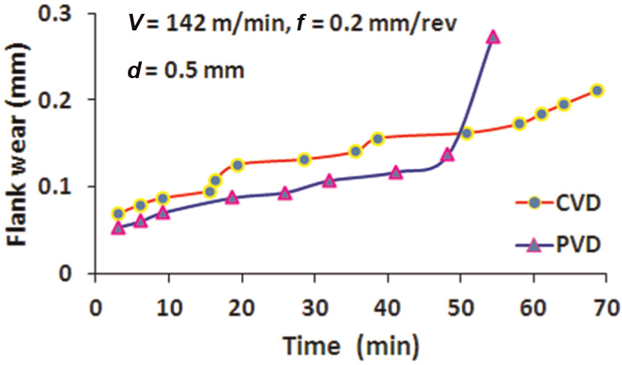
Flank wear progressions of PVD- and CVD-coated inserts at condition index 1.
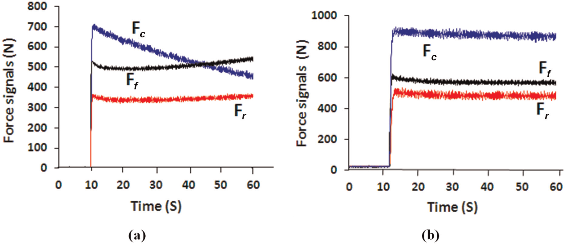
The typical dynamic force signals recorded by the dynamometer for PVD- and CVD-coated inserts with the fresh cutting edge are shown in Figure 7(a) and (b), respectively. The tangential force (Fc) signal having largest magnitude followed by feed (Ff) and radial (Fr) force signals are shown in Figure 7(a) and (b). However, the cutting forces increased with the progress of flank wear and increased suddenly when the tool failure occurred. With the progress in tool wear, increase in the cutting forces, especially feed and radial forces, is shown in Figure 8(a) and (b) for PVD- and CVD-coated inserts, respectively. Increasing trend of feed and radial force signals, as shown in Figure 8(a), indicates the catastrophic failure of the PVD-coated tool, which shows that change in cutting forces represents an accurate and reliable approach to assess tool wear and failure. Sevilla et al. 23 also proposed the methodology for detecting tool failures using vibration signals at different process parameters.

Dynamic force signals measured by the dynamometer for fresh cutting edge at V = 200 m/min, f = 0.2 mm/rev and d = 1.5 mm for (a) PVD-coated insert and (b) CVD-coated insert.
Dynamic force signals measured by the dynamometer at V = 200 m/min, f = 0.2 mm/rev and d = 1.5 mm, beyond the flank wear length of 0.2 mm for (a) PVD-coated insert and (b) CVD-coated insert.
A tool life model for PVD-coated inserts was developed based on experimental observations. The unknown coefficients, exponents of cutting speed, feed and DOC and constant values were determined by minimising the least squares error between the experimental and predicted tool life values at different cutting conditions as given in Table 7. Data-Fit software (version 8.1) was used to find the unknown coefficients. Developed tool life model for PVD-coated inserts is expressed as
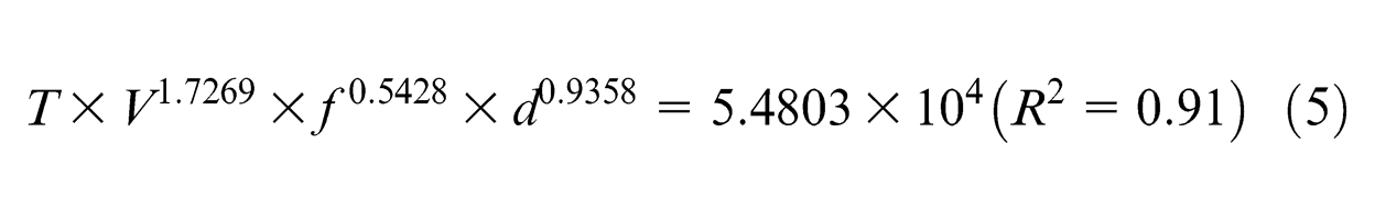
The R2 value of tool life model is more than 0.9, and shows that the developed model could be used to predict the tool life during turning of AISI 4340 steel within the domain of the cutting parameters selected. Plot showing the predicted values of tool life (obtained using equation (5)) along with the experimental values is shown in Figure 9. Experimental values of tool life obtained for CVD-coated inserts from the authors’ earlier work, 15 is also plotted in Figure 9. In this reported work, 15 authors of this study have developed a model to predict the tool life of CVD-coated inserts during turning of AISI 4340 steel using the same domain of the cutting parameters as used in this study, expressed as
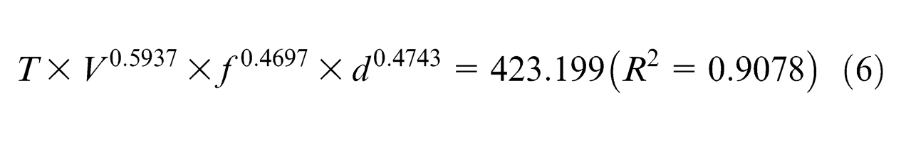
From exponent and constant values of tool life equations (equations (5) and (6)), it can be seen that cutting speed followed by DOC and feed become the most influencing parameters on tool life. However, this effect can be seen as more prominent for PVD-coated inserts, showing higher values of exponents than for CVD-coated inserts, which can also be seen from the curves plotted using equations (5) and (6) for PVD- and CVD-coated inserts, as shown in Figure 10(a)–(c). Figure 10(a) depicts variation in tool life with cutting speed, plotted using feed and DOC values of 0.2 mm/rev and 0.8 mm, respectively. Similarly, Figure 10(b) and (c) depicts variation in tool life with feed and DOC, respectively, plotted using the values of other parameters, V = 200 m/min and d = 0.8 mm, for Figure 10(b), and V = 200 m/min and f = 0.2 mm/rev, for Figure 10(c). It can be seen that PVD-coated TiAlN inserts produced lower tool life than CVD-coated inserts for all the cutting conditions investigated. The higher tool life obtained for CVD-coated inserts can be attributed to the characteristics offered by the thick coating (total thickness of 18 µm) comprising three coating layers, namely, outermost layer of TiN, intermediate layer of Al2O3 (aluminium oxide) and inner layer of TiCN (titanium carbonitride). 16
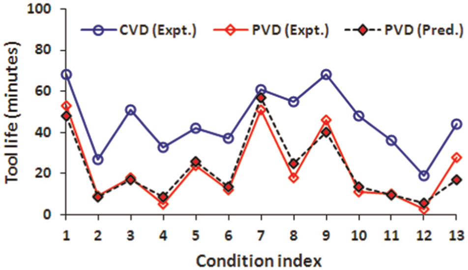
Comparison between experimental and predicted values of tool life for PVD- and CVD-coated inserts.
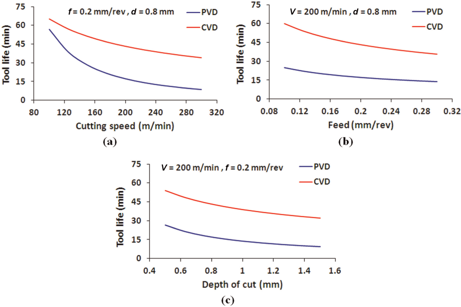
Tool life of PVD- and CVD-coated inserts varying with (a) cutting speed (b) feed and (c) depth of cut.
Optimisation of cutting conditions
The aim of this section is to draw attention to the fact that the optimisation studies performed without considering tool life may not give a realistic optimum solution. There are several studies available in which cutting parameters were optimised considering surface roughness or cutting force(s) or both by performing short-run experiments. However, the tool life, being an important aspect, was not considered for optimising the cutting conditions.
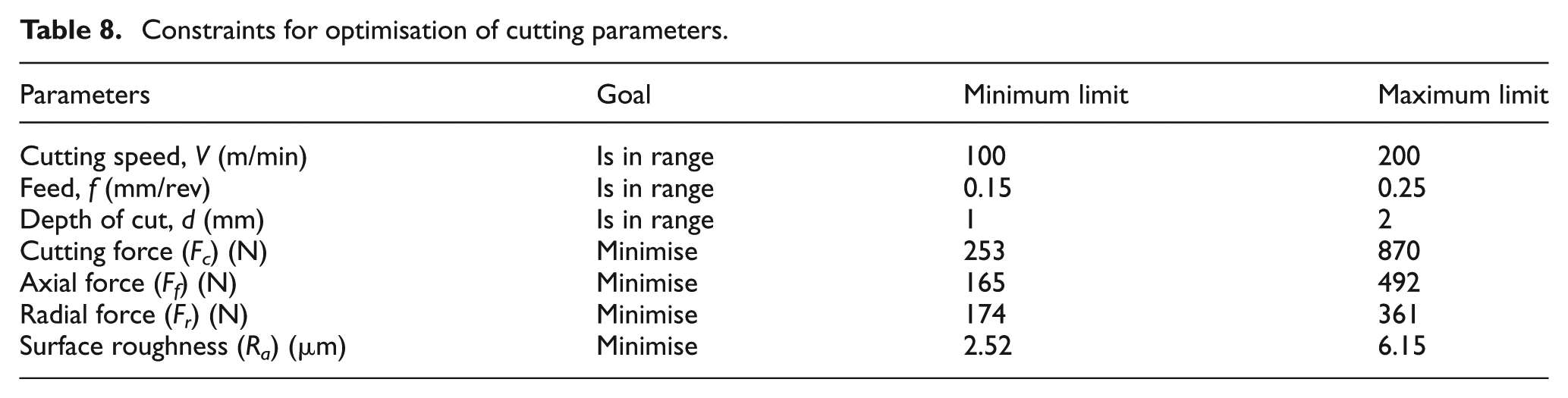
To clearly understand the above fact, in the first phase of discussions, cutting parameters were optimised based on the responses obtained during single-pass experiments, namely, cutting forces and surface roughness (module 1). The goal was to find optimum values of cutting parameters to minimise the above mentioned response functions. Range for cutting parameters and response functions are given in Table 8. Highest limit of cutting speed was limited to 200 m/min as reported by Chinchanikar and Choudhury. 16 Maximum and minimum values for corresponding response functions are selected from Table 3. The Design Expert software, version 7.0, was used to find the optimum cutting conditions. A set of optimum solutions generated, which ensures minimum cutting forces and surface roughness, is given in Table 9 (columns 1–4). It can be seen that the lower feed and DOC values of 0.15 mm/rev and 1 mm, respectively, and cutting speed of 200 m/min are the optimum cutting parameters, which ensure minimum cutting forces and surface roughness, as shown by their highest desirability level (DPSR) of 0.91 (column 5 of Table 9). Tool life of 16 min (calculated using equation (5)) can be obtained for the above optimum cutting parameters. Although the above mentioned cutting condition ensures minimum cutting forces and surface roughness, it may not be a realistic optimum solution from the tool life point of view, which is explained hereafter.
Constraints for optimisation of cutting parameters.
Optimised cutting parameters for PVD-coated inserts.
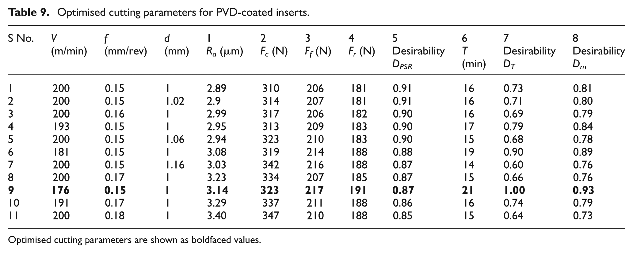
Optimised cutting parameters are shown as boldfaced values.
A desirability function approach, presented by Derringer and Suich, 24 was used for simultaneously optimising the cutting forces, surface roughness and tool life (module 2). This optimisation module selects a most optimum cutting condition, which gives better tool life among the solutions generated in module 1, which ensures minimum cutting forces and surface roughness. A detailed procedure to obtain the optimum cutting parameters considering tool life aspect is reported by Chinchanikar and Choudhury. 15 In this work, optimum cutting parameters for PVD-coated inserts considering the tool life aspect were obtained using a similar approach to that discussed by Chinchanikar and Choudhury. 15 Initially, tool life was calculated for each of the solutions generated in module 1, using equation (5). Then, desirability for tool life (DT) was calculated using one-sided transformation. In one-sided transformation, desirability function increases as response function increases (maximisation problem) or decreases (minimisation problem). It can be expressed as
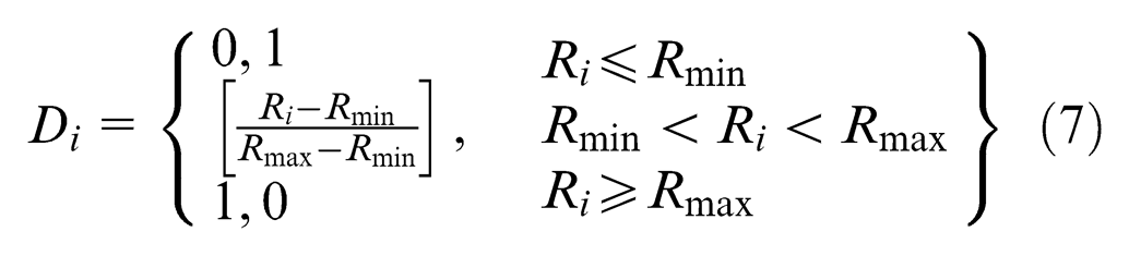
where, Rmax and Rmin are the maximum and minimum limit of the response function; in this case, it is tool life. Ri is response function values for which desirability is to be found out. In this case, tool life values calculated for each of the solutions generated in module 1 are Ri. Therefore, equation (7) can be expressed as
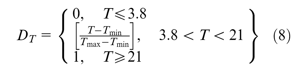
Minimum limit of tool life was calculated by substituting the higher values of cutting conditions in equation (5) (V = 300 m/min, f = 0.3 mm/rev and d = 1.5 mm). Maximum limit of tool life was selected from the set of values of Ri calculated for each of the solutions generated in module 1. In this way, DT was calculated for each of the solutions generated in module 1 and is shown in column 7 of Table 9. It can be seen that desirability for tool life is only 0.73 for the optimum solution calculated in module 1, which cannot be a realistic optimum solution from the tool life point of view. Then, a single desirability function (Dm) was calculated, which is the geometric mean of the desirability level obtained in module 1 (column 5 of Table 9), DT (column 7 of Table 9), and is shown in column 8 of Table 9. The solution having the highest desirability is the optimum solution, which ensures minimum cutting forces, surface roughness and better tool life as shown by boldfaced values in Table 9.
It can be seen that a cutting speed of 176 m/min and lower values of feed and DOC of 0.15 mm/rev and 1 mm, respectively, are the optimum cutting conditions, when tool life was considered as one of the important factors in the optimisation study along with the cutting forces and surface roughness responses. Almost no significant difference in the values of cutting forces and surface roughness can be seen (serial number 1 and 9 from Table 9), as the cutting conditions optimised only for the minimum cutting forces and surface roughness. A significant improvement in tool life, almost 31%, can be seen by selecting cutting speed of 176 m/min and lower values of feed and DOC, which can be considered as a realistic optimum cutting condition for PVD-coated inserts. However, with CVD-applied multi-layer TiCN/Al2O3/TiN-coated carbide inserts, cutting speed of 235 m/min and feed and DOC values of 0.15 mm/rev and 1 mm, respectively, were observed as optimum cutting parameters, which ensures minimum surface roughness and incurred lower cutting forces and produces better tool life. 15 However, magnitudes of these responses were higher in comparison to that obtained by PVD-coated inserts. A group of researchers also observed better surface finish with PVD-coated single-layer TiAlN inserts and better tool life with multi-layer CVD coatings.4,5 The results obtained are found to be in agreement with the other studies.
Conclusion
Experimental investigations to optimise and compare the machining performance, namely, cutting forces, surface roughness and tool life of PVD-applied single-layer TiAlN-coated carbide inserts with CVD-applied multi-layer TiCN/Al2O3/TiN-coated carbide inserts were carried out during turning of hardened AISI 4340 steel (33-35HRC). It has been observed that PVD-coated inserts produced lower values of surface roughness and incurred lower cutting forces than CVD-coated inserts. However, these performance benefits can be availed with a sizeable tool life of more than 20 min by using a cutting speed of 176 m/min and lower values of feed and DOC of 0.15 mm/rev and 1 mm, respectively. It has been observed that cutting speed followed by DOC and feed become the most influencing parameters on tool life. However, this effect was more prominent for PVD-coated inserts. It has been observed that optimisation studies performed considering tool life aspect produces a realistic optimum solution. The correlation coefficients for the three developed components of cutting force, surface roughness and tool life models found to be close to 0.9 indicate that the developed models could be used reliably to predict these responses during turning of AISI 4340 steel within the domain of the cutting parameters selected.
Footnotes
Acknowledgements
This article is a revised and expanded version of an article entitled ‘Investigation of the effects of different coated carbide inserts on surface roughness and cutting force in turning AISI 4340 steel’ presented at the 4th International and 25th All India Manufacturing Technology Design and Research (AIMTDR-2012), India, 14–16 December, 2012. The authors are thankful to Elsevier for providing permission to use three excerpts from the articles titled ‘Effect of work material hardness and cutting parameters on performance of coated carbide tool when turning hardened steel: An optimisation approach’ 15 and ‘Investigations on machinability aspects of hardened AISI 4340 steel at different levels of hardness using coated carbide tools’. 16
Declaration of conflicting interests
The authors declare that there is no conflict of interest.
Funding
This research received no specific grant from any funding agency in the public, commercial or not-for-profit sectors.