
Abstract
This article presents the study of machinability of ZA43 alloy reinforced with silicon carbide particulate metal matrix composites. The specimen was fabricated through conventional liquid metallurgy technique. Silicon carbide with particle size of 60 µm with three different weight percentages (i.e. 5%, 10%, and 15%) was used for fabrication. Dry turning of composite specimens was carried out using uncoated and coated carbide indexible inserts on a conventional lathe. Comparisons of performance of each grade of the cutting tool were carried out in the experiment wherein 162 experiments were executed with the aim of determining surface roughness on the machined area of the composite and wear land on the flank portion of the cutting tool. The results were recorded and analyzed with a statistical analysis tool (analysis of variance) to identify the significant parameter influencing both surface roughness and flank wear. It was observed that cutting speed, feed, and depth of cut were the parameters affecting the surface finish and responsible for higher tool wear. The composition of the material also had substantial effect in deciding the surface roughness value and tool wear land.
Introduction
Metal matrix composites (MMCs) are the category of advanced materials possessing superior properties compared to conventional materials. Improved strength and stiffness of the composite along with low weight finds applications starting from aerospace components to sports articles and also household domestic products. Utilization of composites with distinct application is possible when the material is given a suitable shape. Varieties of methods are available to shape the material, which includes forging, extrusion, rolling, forming, and so on. In these processes, the presence of hard reinforcement in the MMCs will not cause much damage to the processing tools. In spite of all the shaping techniques, machining is the process that is finishes the components to the exact dimensions and surface finish after the shaping process. Machining of the advanced materials is a challenging task as severe tool damage takes place during the process. Because of the great level of difficulty in machining attributed by the presence of hard reinforcement phase in the matrix, these materials find restricted application. Machining of composites can be accomplished by advanced cutting tools that show superior properties than that of conventional cutting tools. Polycrystalline diamond (PCD) and cubic boron nitride are the most widely used cutting tool materials that are very suitable for machining metal matrix and other grades of composites. These advanced cutting tool materials are not affordable as the costs of these tools are very high. This limitation can be overcome by the use of coated and uncoated carbide inserts that can be employed for short runs where desired features on the product can be achieved.1–5
Iuliano et al. 6 did machining experiments on aluminum matrix composite reinforced with alumina particles with uncoated tungsten carbide and diamond-coated tungsten carbide tools where the diamond-coated tools showed low levels of wear during the machining process. Ciftci and Turker 7 worked on machining of aluminum alloy reinforced with SiCp with uncoated and TiC-, Al2O3-, and TiCN-coated carbide tools. The result reveals that coated tools show better performance and increased tool life than uncoated tools. A comparison of both the tools was made in connection with surface finish where uncoated tools produce better finish than that of coated tools.
Davim8–11 worked on machinability of Aluminum-356 reinforced with SiCp composite. A turning operation was carried out with PCD tools. The results of the investigation show that surface roughness was affected by feed, and cutting force was influenced by speed and flank wear. An increase in cutting speed resulted in increased flank wear, and it was due to abrasion. Muthukrishnan et al.12–14 worked on machining of aluminum-based MMC using three different grades of PCD inserts. The results show that surface finish was good with higher cutting speeds and lower feeds but constant formation of built-up edge was observed on the cutting tool.
Manna and Bhattacharyya15–17 worked on machinability of aluminum reinforced with SiCp MMC with uncoated tungsten carbide tool with grade K10. The influence of various cutting parameters on cutting force, flank wear, surface roughness, and built-up edge formation was investigated. The results reveal that higher cutting force and lower flank wear were observed at lower cutting speeds.
Looking at the observations made by different investigations mentioned above, it is clear that there is a lot of scope to study the machinability aspects of MMC with different grades of cutting tools. In the present investigation, machinability of ZA43 reinforced with SiC particle size of 60 µm in three different weight percentages (i.e. 5%, 10%, and 15%) was carried out. Zinc–aluminum alloy is a very good bearing material that has superior wear resistant properties. The presence of aluminum and copper in pure zinc made the material very strong against frictional loss. The commercially available ZA alloy that contains 27% of aluminum shows favorable mechanical properties. When the percentage of aluminum was increased in the zinc, it leads to an increase in the hardness, and the wear resistant nature simultaneously decreases fluidity and elastic properties. When such high aluminum-containing zinc alloy was reinforced with hard ceramic particles, extremely superior wear resistance can be achieved.18–21 Machining of such advanced material was carried out, and machinability properties were investigated under different combinations of cutting speed, feed, and depth of cut.
Experimental work
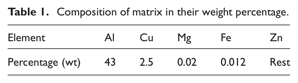
The fabrication of MMC was carried out with conventional stir casting method. Composition of the matrix as given in Table 122,23 was taken and heated above its melting temperature in the crucible. The molten matrix was stirred with a zircon-coated stainless steel impeller until whirl formation took place. Zircon coating was done to prevent diffusion of steel into the matrix, which may alter the composition of the material. To this molten matrix whirl, preheated SiC particles to 400 °C were introduced, and stirring was continued till uniform distribution of particles in the matrix took place. To improve wettability between SiC particles and the matrix, preheating of the particles was carried out. Addition of small amounts of magnesium to the matrix will also improve the wettability.24,25 Required castings with 5%, 10%, and 15% SiC were obtained by pouring the mixture into a cast iron die of diameter of 42 mm and left there to attain room temperature. A scanning electron microscopic (SEM) micrograph with 5% SiC was taken to study the particle distribution in the matrix that is given in Figure 1. The particle distribution was found to be uniform, and at some portions, clustering of particles was observed.
Composition of matrix in their weight percentage.
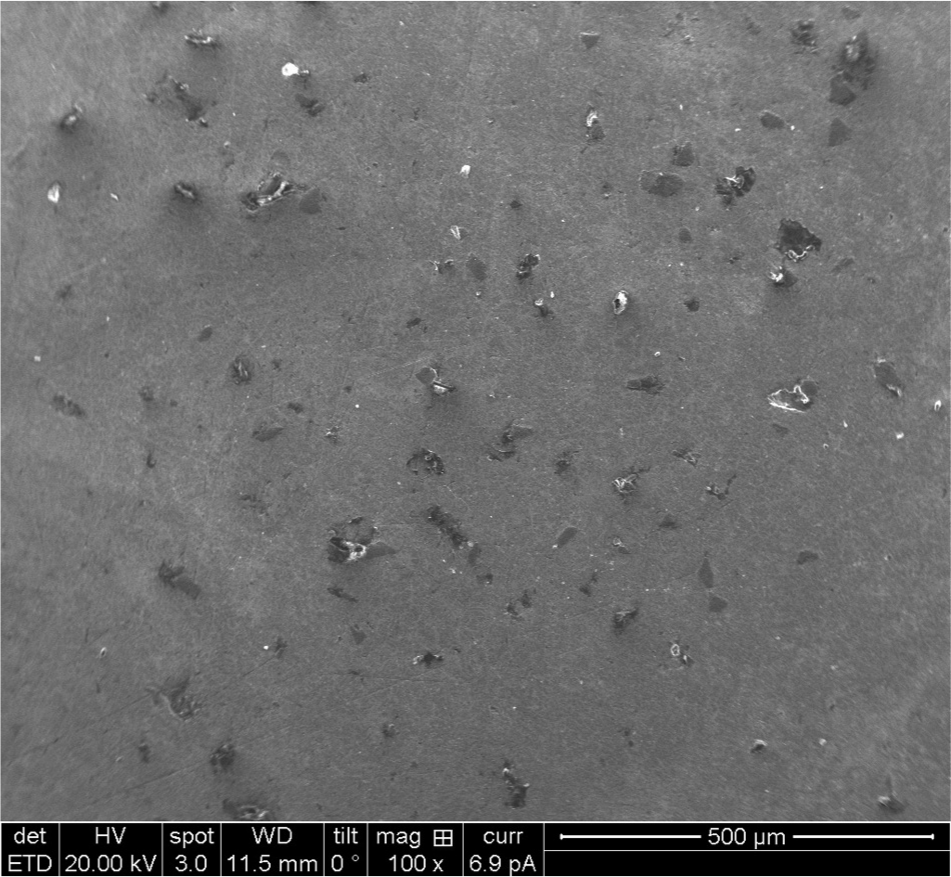
SEM micrograph showing SiC particle distribution (SiC 5%).
The fabricated specimens were turned under dry condition on a conventional lathe with different sets of machining conditions. Two grades of commercial cutting tools (i.e. uncoated carbide insert SNMG 090308 K15 and multilayered coated carbide insert SNMG 090308 K15 with TiN, TiCN, Al2O3, and TiN coating) were used for the study. Each trial was executed with a new cutting edge of the tool, and 75 mm length of turning was carried out. After each trial, the specimen was unloaded from the machine, and the surface was checked for the roughness value (Ra) using a Mitutoyo Talysurf. During machining, the tool undergoes damage, and at the end of each trial, the tool was removed from the holder, and average flank wear was measured using a Mitutoyo microscope with 30× magnification. The selected machining parameters at different levels are given in Table 2. The experiments with 162 trials were executed, and for all the trials, surface roughness and tool wear values were measured and recorded.
Assignment of levels to the factors.
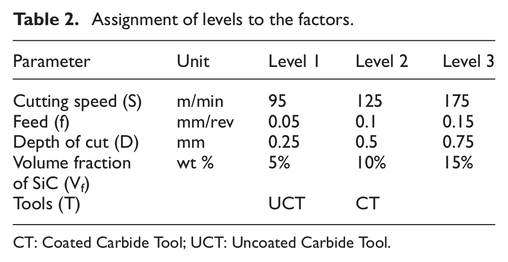
CT: Coated Carbide Tool; UCT: Uncoated Carbide Tool.
Results and discussion
Effect of machining parameters and tool on surface roughness
The effect of cutting speed on the surface produced during the machining of ZA43 MMC is presented in Figure 2. The graph is plotted for the results of uncoated carbide tool on surface roughness. It was observed that for the feed of 0.05 mm/rev, depth of cut of 0.25 mm, MMC with 5% SiC at cutting speed of 95 m/min shows Ra value of 2.05 µm. For the same set of machining conditions, cutting speed was increased to 175 m/min, which resulted in an Ra value of 1.29 µm. Experiments were also conducted on MMC with 10% and 15%. The trend resembles the same pattern, that is, decreasing surface roughness with increasing cutting speed, but higher Ra values were observed for higher reinforcement percentages. By observing the trend, it is clear that the roughness value decreases with an increase in cutting speed. At higher cutting speeds, the matrix becomes soft and tries to adhere to the tool to form a built-up edge. At the same time, the side way flow of the chips at higher cutting speeds prevents the formation of built-up edges. Pramanik et al. 26 reported a similar phenomenon to obtain a better finish at higher cutting speed. Hence, lower Ra values can be achieved at higher cutting speeds.
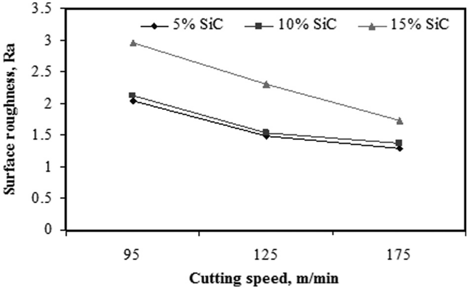
Variation of surface roughness with cutting speed (feed of 0.05 mm/rev, depth of cut of 0.25 mm, and uncoated tool).
A comparison of performance of uncoated and coated carbide tools was made in connection with surface roughness and is presented in Figure 3. It was observed from the graph that uncoated carbide tools produce better surfaces than coated carbide tools. MMC with 5% was machined using both the category of cutting tools with feed of 0.05 mm/rev, depth of cut of 0.25 mm, and cutting speed of 95 m/min, and the Ra value observed for the uncoated tool was 2.05 µm and for the coated tool was 2.71 µm. A similar behavior was observed for other sets of machining conditions. This variation in Ra is due to the presence of coating on the cutting tool that exhibits higher roughness on the coated surface than the tool substrate. Hence, it becomes easy for the matrix material to adhere to the surface of the coating and pile up on the cutting edge of the tool to form a built-up edge. The tool with built-up edge produces poor finish on the workpiece.
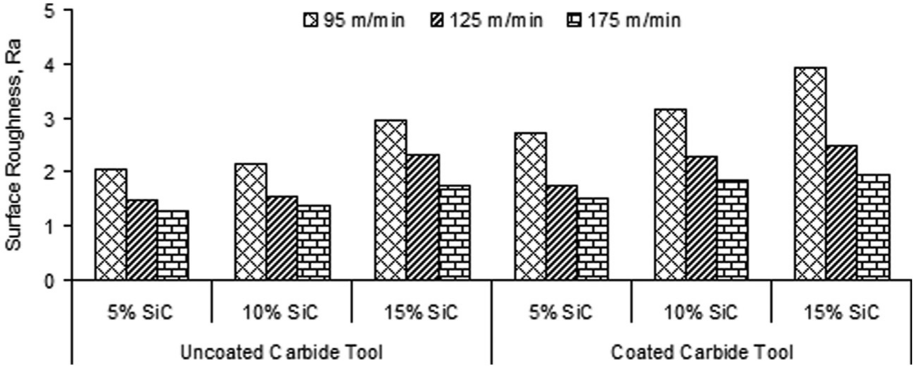
Comparison of performance of uncoated and coated carbide tool with cutting speed and reinforcement percentage (feed of 0.05 mm/rev and depth of cut of 0.25 mm).
Reinforcement percentage in the MMC was the influencing factor on surface finish. It was observed from Figure 3 that increase in the SiC content will result in increased surface roughness. Anandakrishnan and Mahamani 27 investigated flank wear, surface roughness, and cutting force development during machining of aluminum-reinforced TiB2 MMC. The results of the study reveal that increase in the reinforcement volume fraction in the MMC increases the surface roughness during the machining process. MMC with 5% SiC shows a roughness value of 2.05 µm where a 15% resulted in an Ra value of 2.96 µm. For both coated and uncoated carbide tools, a similar trend was observed. When SiC percentage in MMC was increased, the number of impacts caused by reinforcement particles on the cutting tool also increases. The cutting edge of the tool undergoes severe damage, even chipping of the cutting edge was observed with increased SiC percentages. The damaged tool produces a poor surface on the workpiece and hence surface roughness increases. Generally, built-up edge formation was observed when the friction between tool and workpiece increases. The increased friction was observed with increased depth of cut, higher reinforcement, and lower cutting speeds. This built-up edge on the cutting tool is also responsible for the poor surface finish. Even increased roughness on the machined area was the result of pullout of the hard ceramic particle from the MMC. The formation of the pit due to this pullout phenomenon from the soft matrix was responsible for the increased roughness. As the concentration of the SiC in the MMC increases, the number of pits formed on the machined surface in a unit area also increases, which leads to increased surface roughness.
Influence of feed on Ra was evaluated by keeping cutting speed constant at 95 m/min, depth of cut of 0.75 mm, and uncoated carbide tool. Figure 4 shows the variation of Ra with increasing feed rate. Machining was carried out for all three reinforcement compositions. It was observed that an increase in the feed results in an increase in surface roughness. MMC with 5% SiC was turned with a feed of 0.05 mm/rev, and the Ra value observed was 2.16 µm. For the same experimental condition, feed was increased to 0.15 mm/rev, which resulted in higher Ra value of 2.54 µm. Relatively, similar trends were observed with higher Ra value for MMC with higher reinforcement percentage. Manna and Bhattacharyya 17 reported built-up edge formation decreases with increase in the cutting speed and feed. But for the present situation, reduction in the built-up edge formation on the tool produces increased Ra value. Increase in the feed during machining tends to increase feed marks on the surface, and they become clearer and prominent at higher feed rates. At lower feed rates, the roughness is independent of feed. Thus, surface roughness is reduced at lower feed rates. Behavior of material during machining was studied when higher feed rates cause plowing and fracture of SiC particles, which result in the formation of rough surfaces. Delaminated SiC particles from the matrix will result in the formation of pits on the machined surface. These pits correspond to increased roughness values. Joshi and coworkers28,29 investigated machinability properties of aluminum MMC and found that the surface roughness was affected by feed and tool nose radius.
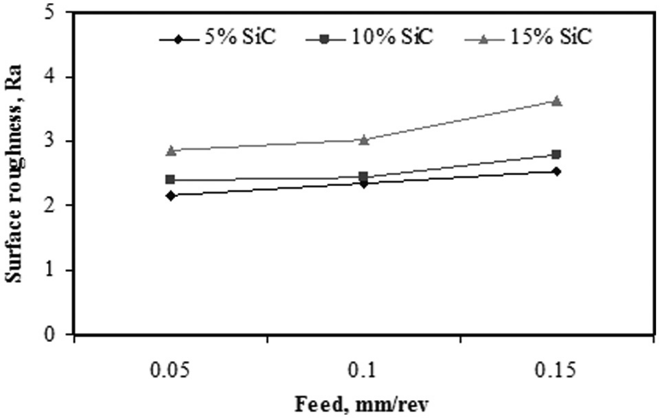
Variation of surface roughness with feed and SiC percentage (speed of 95 m/min, depth of cut of 0.25 mm, and uncoated tool).
The influence of depth of cut on the surface roughness was studied by keeping cutting speed at 175 m/min, feed of 0.05 mm/rev, and uncoated carbide tooling as constant factors, and depth of cut considered was 0.25, 0.50, and 0.75 mm. All the experiments were executed with a fresh cutting edge of the tool, and surface roughness was checked. It was observed that depth of cut has a negative effect on the surface finish. MMC with 5% SiC at 0.25 mm cut depth resulted in roughness of 1.29 µm, and for 0.75 mm, it was 1.97 µm. With the same machining conditions, MMC with 10% SiC showed a higher Ra value than 5%, and 15% showed an increased Ra value than 10%. But all three materials follow comparatively the same trend across increased depth of cut and are shown in Figure 5. Basavarajappa et al. 30 reported the effect of depth of cut on surface roughness, and their findings reveal that increase in depth of cut increases Ra value.
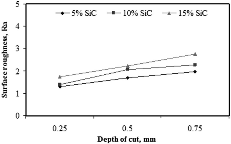
Variation of Ra with depth of cut and SiC percentage (cutting speed of 175 m/min, feed of 0.05 mm/rev, and uncoated tool).
Effect of machining parameters and tool properties on flank wear
Flank wear is one of the mechanisms of tool failure during the machining process. The surface below the cutting edge undergoes damage due to rubbing of the tool with the fresh part of the workpiece or finished part of the workpiece resulting in the formation of land. Higher land formation on the flank weakens the tool, and hence, the performance of the tool decreases. Because of this, the tool cannot produce desired dimensions and finish on the workpiece. The width of the land at flank portion is measured for each trial with the previously considered machining parameters.
Figure 6 shows the variation of flank wear with cutting speed. It is clear from the graph that cutting speed directly affects the flank wear. The experimental trial was carried out with a feed of 0.05 mm/rev, depth of cut of 0.50 mm for all the three compositions of MMC, and coated carbide tool was considered to generate the graph. For the cutting speed of 95 m/min, the amount of flank wear observed for 5% SiC was 0.185 mm. For the increased speed of 175 m/min, the value of flank wear was around 0.56 mm. From this, we can draw the conclusion that an increase in cutting speed will rapidly cause tool failure. A similar trend was observed for MMC with other reinforcement percentages. At higher cutting speeds, the rubbing between the flank of the cutting tool and finished part of the workpiece will be very high. Due to increased abrasive action of SiC particles in the MMC, it will cause the tool to fail with a phenomenon that resembles conventional grinding process. Kilickap et al.31,32 conducted machinability tests on aluminum-based MMC where tool wear and surface roughness were measured. MMC with three reinforcement percentages was machined with a K10 tool. The results reveal that rapid tool wear takes place at higher cutting speeds.
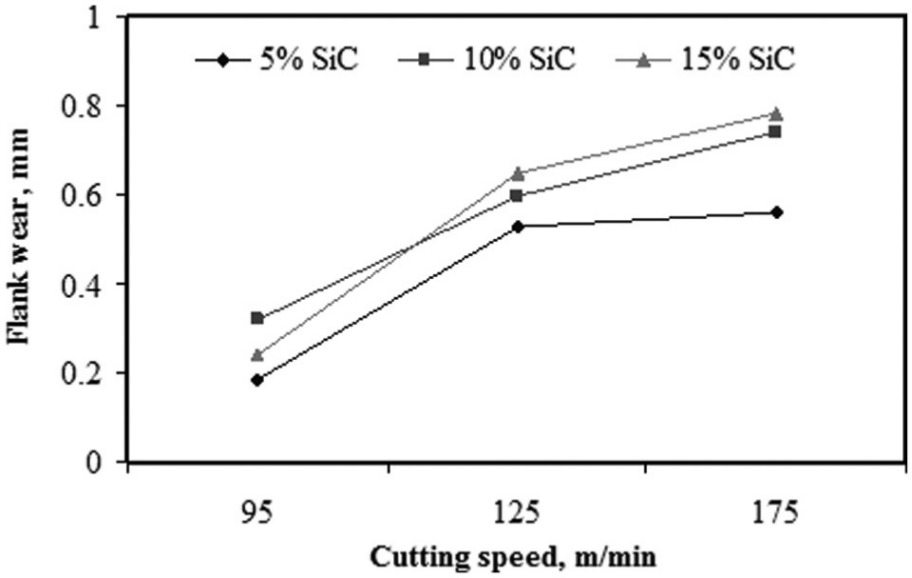
Variation of flank wear with cutting speed and SiC percentage (feed of 0.05 mm/rev, depth of cut of 0.50 mm, and coated carbide tool).
Feed has the similar effect as that of cutting speed on the life of the cutting tool. Figure 7 shows variation of flank wear with increasing feed. To study the effect of feed, all other variables were kept constant and feed was increased (0.05, 0.1, and 0.15 mm/rev). It was observed that flank wear increases with increase in the feed rate. MMC with three reinforcement percentages was machined and 0.452 mm flank wear was observed for machining MMC with 5% SiC with a feed of 0.05 mm/rev. When feed was increased to 0.15 mm/rev, the same material showed a flank wear value of 0.72 mm. Bhushan et al. 33 investigated tool wear and surface roughness during machining of aluminum MMC with carbide and PCD inserts. The results reveal that flank wear increases with an increase in feed rate and reinforcement percentage in the material.
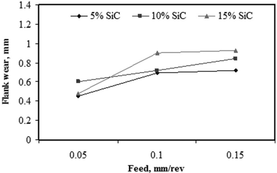
Variation of flank wear with feed (cutting speed of 95 m/min, depth of cut of 0.75 mm, and coated carbide tool).
An increase in depth of cut during machining has a direct effect on the life of the tool. All the three materials were turned with a cut depth of 0.25, 0.50, and 0.75 mm by keeping cutting speed and feed at constant levels. MMC with 5% SiC shows a lower level of land formation (i.e. 0.311 mm at 0.25 mm cut depth). The same material with 0.75 mm cut depth shows wear land of 0.62 mm. Figure 8 clearly indicates that increasing depth of cut will increase the flank wear value. More penetration of the tool into the work material will tend to increase the contact area between the cutting tool and the workpiece. This increased area results in increased friction and finally ends with tool damage. Two types of tool damage mechanisms occur during the machining of particulate MMC with increased depth of cut. Two-body and three-body abrasion mechanisms take place between the tool and workpiece. In two-body abrasion, the particles embedded in the matrix grind the cutting edge of the tool resulting in severe tool wear. But in three-body abrasion, the free particles that were delaminated from the matrix come in between the tool and the work causing flank wear. Because of these two mechanisms, severe damage to the cutting tool takes place. Muthukrishnan and Davim 14 investigated machinability properties of aluminum-based MMC concentrating on tool wear and surface roughness. The findings of their work indicate that increased flank wear was observed with an increase in depth of cut, which was due to two-body and three-body abrasion mechanisms.
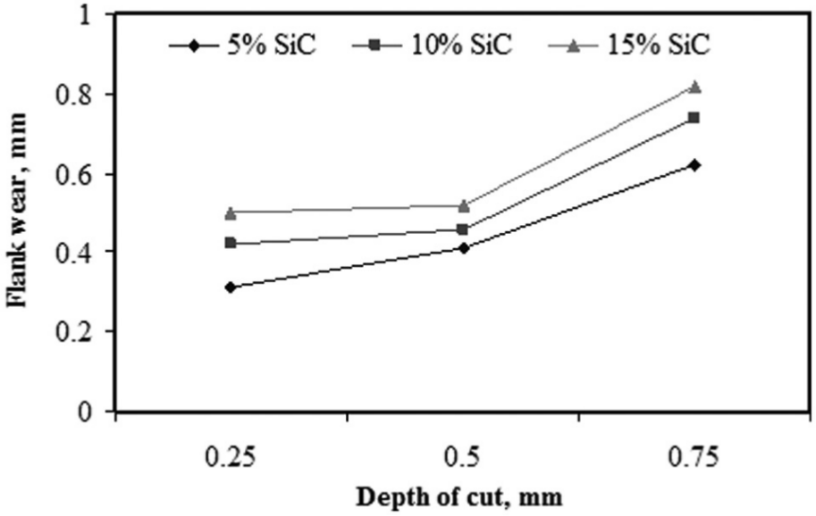
Variation of flank wear with depth of cut and reinforcement percentage (cutting speed of 175 m/min, feed of 0.05 mm/rev, and uncoated tool).
The tool life of uncoated and coated carbide inserts was studied by machining MMC with previously defined machining conditions. Figure 9 shows the histogram of flank wear at a constant feed of 0.05 mm/rev. Three cutting speeds were employed to study the behavior of the tool with abrasive reinforced matrix. It was observed that the life of a coated carbide tool was superior compared to an uncoated carbide tool. The presence of TiN, TiCN, and Al2O3 coating on the cutting tool prevents the abrasive action of SiC particles. The performance of the coated tool was better with MMC until the coating got damaged. Once damage occurs on the flank face of the tool, severe damage takes place within a very short span. Ciftci and Turker 7 conducted machining tests on SiCp-reinforced aluminum MMC and reported that the life of coated carbide cutting tools was longer due to the presence of the coating and that uncoated tools produce better surface quality. The percentage of reinforcement content in MMC also affects the tool to a greater extent. It was observed from the micrograph (Figure 10) that formation scratch marks on the flank of the cutting tool are due to abrasive action of the particles in the MMC. The loss of tool material in the form of scratches increases with an increase in the concentration of the SiC particles in the MMC. Kannan et al. 34 investigated the role of reinforcement on tool performance during cutting of MMC, and he found that increase in the reinforcement concentration for a constant reinforcement size severely damages the cutting tool. Hence, from the above discussion, it can be concluded that increase in the SiC content in the MMC leads to increased flank wear (Figures 11 and 12).
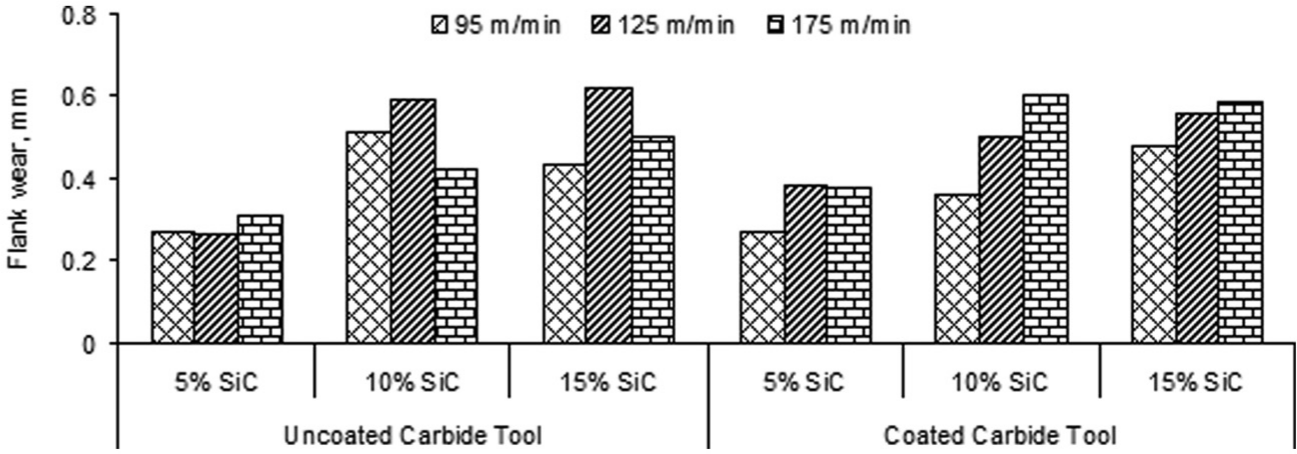
Flank wear comparison for uncoated and coated carbide tools with cutting speed and material composition (feed of 0.05 mm/rev)
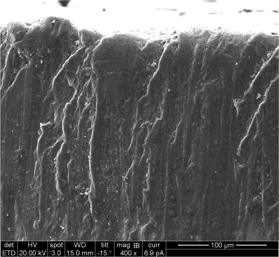
Formation of scratch marks due to abrasion on uncoated carbide tool.
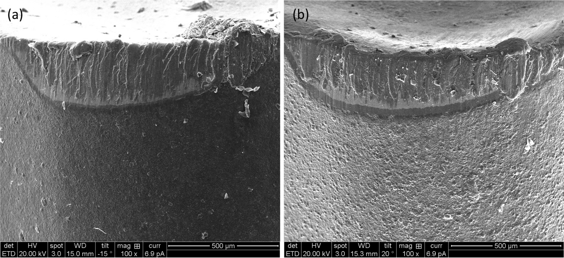
Micrograph of flank wear for (a) uncoated and (b) coated carbide tools with cutting speed of 95 m/min, feed of 0.05 mm/rev, and depth of cut of 0.25 mm.
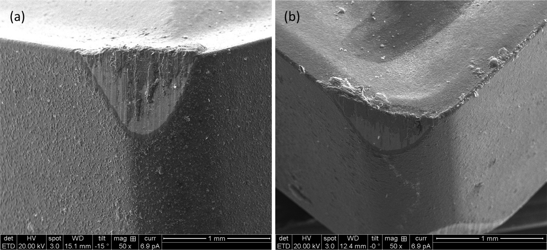
Micrograph of flank wear for (a) uncoated and (b) coated carbide tools with cutting speed of 175 m/min, feed of 0.15 mm/rev, depth of cut of 0.75 mm
SEM micrographs were taken to study the nature of tool wear at different working conditions and during the machining of different compositions of the material. It was observed from the micrograph (Figure 11(a) and (b)) that the extent of tool damage in uncoated carbide tools will be more compared to coated carbide tools under identical machining conditions. The area of land formed on the flank portion of the uncoated tool was greater and abrasion marks due to SiC particles on the flank were very clear. But in coated tools, the presence of coating resists the abrasive action of reinforcing particles to a greater extent; hence, damage to the flank is reduced. The micrographs (Figure 12(a) and (b)) were also taken for higher machining parameters wherein the amount of land formation on the cutting tool was greater for higher cutting speed, feed, and depth of cut. It was observed that the amount of material deposited on the cutting tool was more for the coated carbide tool. Muthukrishnan and Davim 14 found that majority of tools, while machining of MMC, undergo abrasive wear with the formation of scratch marks on both flank and face portions of the cutting tool.
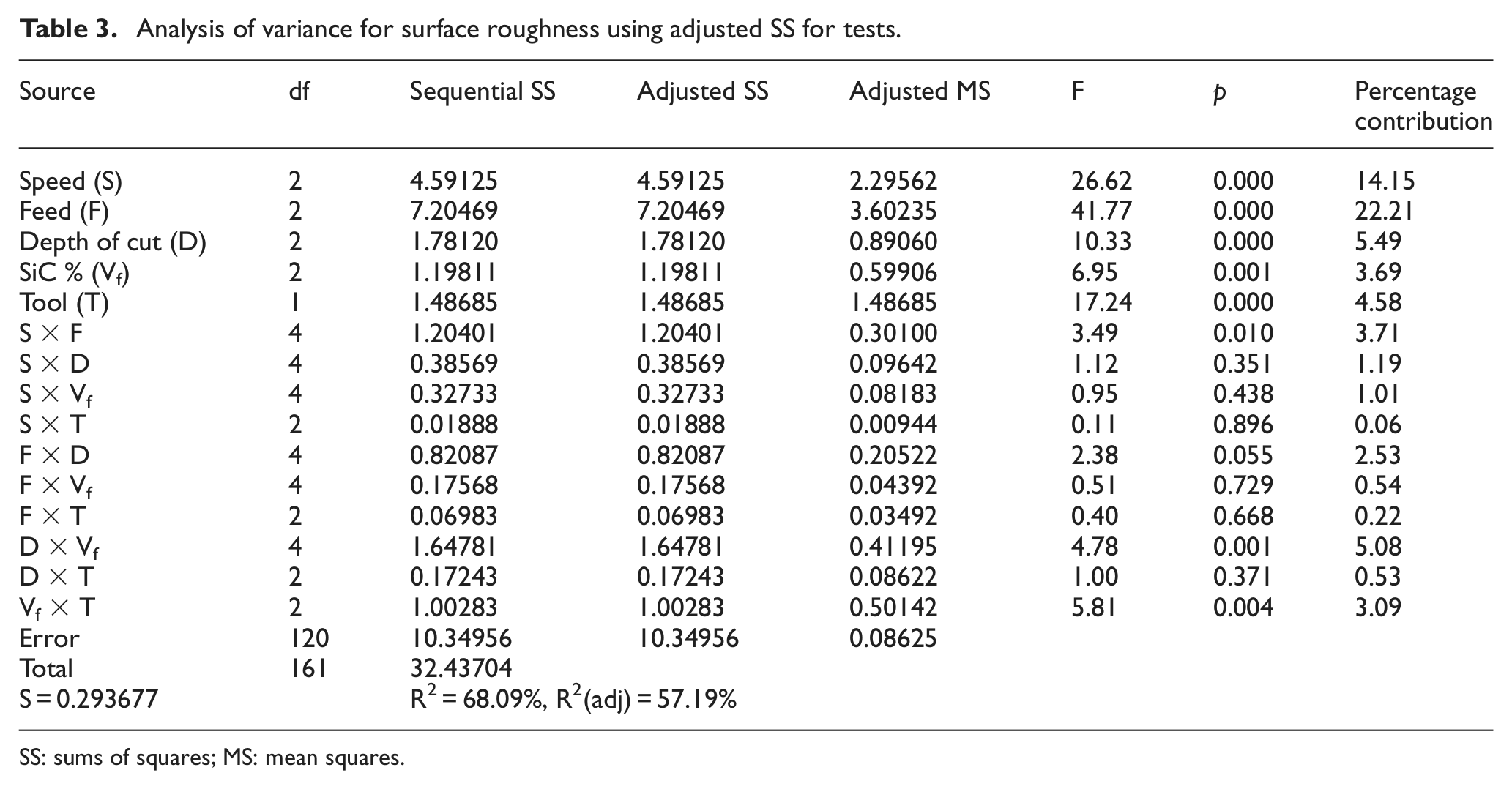
The experimental results were analyzed using analysis of variance (ANOVA), for identifying the factors significantly affecting the surface roughness and flank wear. The results of the ANOVA for surface roughness and flank wear are given in Tables 3 and 4. The analysis was carried out for a significance level of α = 0.05 (i.e. for a confidence level of 95%). A p-value less than 0.05 is considered to be statistically significant and contributing to the surface roughness and flank wear. Main effect and two-level interactions between parameters on the result were studied, and their percentage contribution on output was determined using Minitab statistical software.
Analysis of variance for surface roughness using adjusted SS for tests.
SS: sums of squares; MS: mean squares
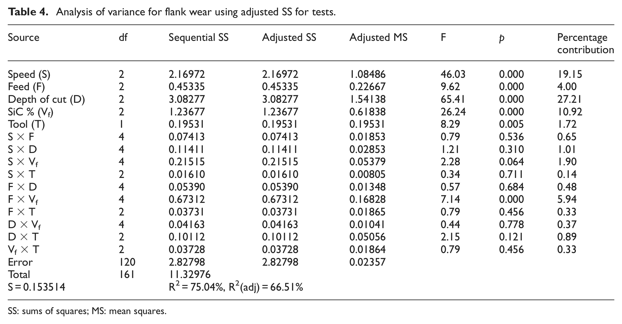
Analysis of variance for flank wear using adjusted SS for tests.
SS: sums of squares; MS: mean squares.
By observing the values obtained in the ANOVA (Table 3), it is very clear that feed and cutting speed are the most contributing parameters in deciding surface roughness with 22.21% and 14.15%, respectively. This indicates surface roughness was greatly affected by feed and cutting speed where lower feed and higher speed produce better finish and higher feed and lower cutting speed result in poor finish. Depth of cut, volume fraction of SiC, and tool used are also significant parameters, but their percentage of contribution was less. Two-level interactions were studied to check the combined effect of parameters on the output. It was observed that combination of depth of cut × volume fraction, speed × feed, and volume fraction × tool contributing more for surface roughness with 5.08%, 3.71%, and 3.09%, respectively. The other interactions can be neglected as their contribution percentage in deciding the surface roughness was much less. A main effect plot for the signal-to-noise ratio was drawn to identify the optimum machining conditions, where better surface finish can be obtained. It was observed from Figure 13 that by selecting machining conditions with a speed of 175 m/min, feed of 0.05 mm/rev, and depth of cut of 0.25 mm, a better surface finish can be achieved for the material containing 5% reinforcement and by using uncoated carbide tool.
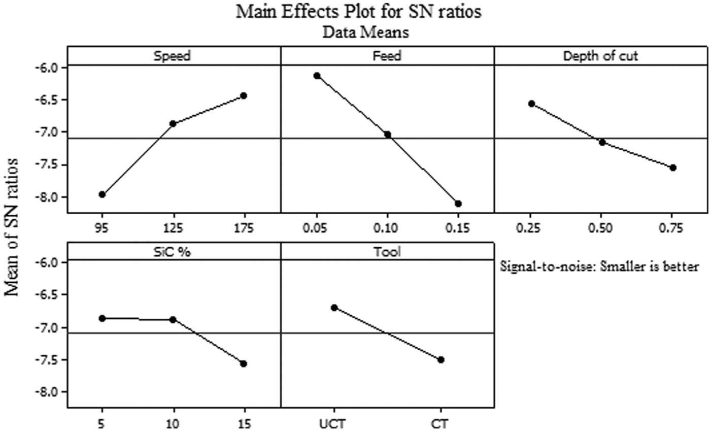
Main effect plot for machining parameters, material composition, and tool versus SN ratio of surface roughness.
ANOVA was also done on the results of machining to identify the factors affecting the flank wear. By observing the values of ANOVA given in Table 4, it is clear that depth of cut, cutting speed, and volume fraction of composite significantly affect tool wear with 27.21%, 19.15%, and 10.92%, respectively. Two-level interactions between parameters were studied where combination of feed × volume fraction was the only combination whose effect was more on the tool wear. Other sets of combinations show very less contribution in deciding the tool wear value. To get longer tool life with less flank wear, the optimum parameters include cutting speed of 95 m/min, feed of 0.05 mm/rev, and depth of cut of 0.25 mm. This combination of machining parameters should be employed on the material with 5% reinforcement. It was discussed previously that coated tools will have more life than uncoated carbide inserts and it is given in Figure 14.
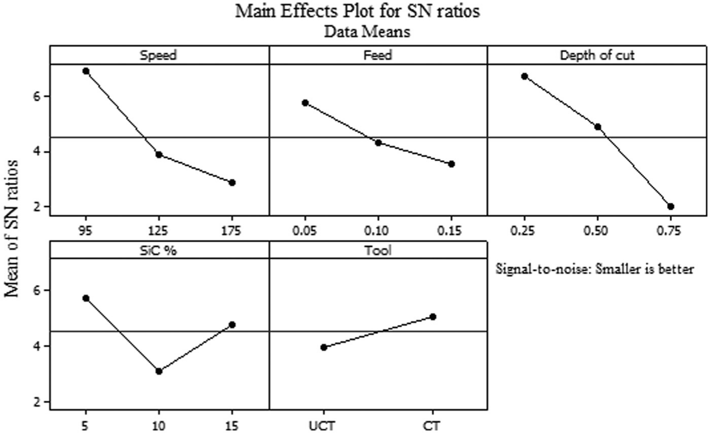
Main effect plot for machining parameters, material composition, and tool versus SN ratio of flank wear.
Conclusion
In the present investigation, ZA43 reinforced with SiC was machined with two grades of cutting tools, namely, coated and uncoated carbide inserts. The performance of these tools on different compositions of MMC was studied. Machining parameters were varied, and 162 experiments were executed under dry condition with various combinations of cutting speed, feed, depth of cut, and two grades of tools. During the conduction of the experiments, surface finish and flank wear were measured. The findings of the experiments are discussed as follows:
There is an inverse effect of cutting speed on the surface produced during turning. As cutting speed was increased from 95 to 175 m/min, surface roughness decreased. This happens due to the softening effect of the material at higher cutting speeds, and built-up edge formation is almost negligible at higher cutting speeds.
Feed has a direct effect on the surface roughness. With a lower feed rate of 0.05 mm/rev, the distance between feed marks will be less. But at a higher feed of 0.15 mm/rev, these marks become prominent and clearly visible due to increased distance between marks. Hence, roughness increases. Even plowing of the material and fracture of the particles were observed at higher feed rates leading to increased roughness values.
Depth of cut is also an influencing parameter to the surface roughness. Increase in the depth of cut leads to increased surface roughness. At depth value of 0.25 mm, the area of contact between tool and workpiece will be less. But at increased depths, the tool pierces the material and there will be more area of contact leading to increased friction and built-up edge formation. The tool with a built-up edge is responsible for the formation of a rough surface.
Surface finish was instigated by the type of tool used for the machining process. From the results, it was observed that uncoated carbide tools produce better surface finish than coated carbide tools. The coated carbide tools are prone to have a built-up edge, which results in poor finish.
The obtained roughness values during the experiment were analyzed using ANOVA, and analysis implies that feed has a greater contribution of 22.21% in deciding the surface finish. Cutting speed is a second influencing parameter with 14.15% contribution and depth of cut has less contribution of 5.49% on surface roughness. The interaction between depth of cut × volume fraction of the reinforcement in the material had a greater influence than any other combinations.
Tool wear was measured during the experiment for both coated carbide and uncoated carbide tools. The depth of cut had the highest effect on the flank wear. As depth of cut was increased, the penetration of the tool into the workpiece increases and abrasive particles in the material cause severe damage to the cutting tool.
An increase in the cutting speed leads to an increase in the flank wear. At higher cutting speed, the rubbing between the flank of the cutting tool and finished part of the workpiece will be very high. An increased abrasive action of SiC particles in the MMC causes the tool to fail. The mechanisms for tool failure were two-body and three-body abrasion mechanisms.
Feed also has greater impact on the flank wear. Increase in the feed rate results in an increase in flank wear.
Flank wear values of coated and uncoated carbide tools were compared. It was observed that coated carbide tools sustain better against abrasive action of the MMC, whereas uncoated tools undergo severe damage during machining. This is due to the presence of the coating on the tool, which improves the abrasive wear resistant property of the cutting tool. The results of ANOVA clearly acknowledge that coated carbide tools outperform the uncoated carbide tools. SEM micrographs support the above said statements.
Footnotes
Funding
This research received no specific grant from any funding agency in the public, commercial, or not-for-profit sectors.