
Abstract
This article aims to improve the absolute accuracy of an individual industrial robot by means of integrating itself with the workspace Measuring and Positioning System, which is currently under development at Tianjin University, China. We found that the absolute positioning error persists in the robot base frame, whereas the errors, both in position and orientation, can be reduced by changing the reference frame from the robot to the integrated metrology system, that is, the workspace Measuring and Positioning System. What it needs more is several additional corrective movements. And this correction work just needs roughly calibrated parameters between the robot frame and the workspace Measuring and Positioning System frame. To validate it, we present the experiment which demonstrates that the absolute error of the industrial robot can be less than 0.2 mm by virtue of the workspace Measuring and Positioning System and the convergent corrective movements. Aiming to explain the results, this study deduces the mathematical model in detail about the integration of the robot with the workspace Measuring and Positioning System. The model explains why the integration of the robot with the workspace Measuring and Positioning System applies. First, the model tells that there exists a low requirement, that is, the tolerable rough level of the parameters between the robot frame and the workspace Measuring and Positioning System frame, for assuring the convergence of the corrective movements. Second, the relationship among the relevant factors in the corrective process is given. Finally, besides the workspace Measuring and Positioning System, this model is of general significance for any available metrology systems with which the industrial robot can integrate, and it may also provide theoretical instructions for the improvement of the robot off-line programming, that is, the robot can work at a higher accuracy provided by the integrated metrology system.
Keywords
Introduction
The absolute accuracy of an industrial robot is relatively poor compared with the good repeatability in the manufacturing industry.1–4 While the machining robot repeatability remains within the submillimeter range (±0.3 mm), the absolute accuracy varies significantly and can be well above the millimeter mark (±5–10 mm) toward the boundary of the working envelope. 5 This lack of accuracy has limited the usage of the robot in many fields such as automotive, aerospace and aeronautics, moulds and die, and high-precision components.6–10 Aiming at pioneering a new generation of adaptive production systems,11,12 the European Union-funded research program COMET (COMET Project-Plug and Produce COMponents and METhods for adaptive control of industrial robots enabling cost-effective, high-precision manufacturing in factories of the future) has listed the three most critical limitations currently preventing the use of robots in typical machining applications, the first being is the lack of absolute positioning accuracy.8,13
Large-volume metrology systems14–17 with which robots can integrate provide numerous alternatives for improving absolute positioning accuracy in robotic workcells, that is, transferring the accuracy problem to the integrated metrology system, 18 as opposed to simply making use of calibration procedures.19–22 There are two issues: one is the selection of a metrology system and the other is the method or principle that links the robot and metrology system together without reducing the accuracy of the integrated metrology system.
For the first issue, metrology systems including theodolite network,23,24 digital photogrammetry,23,25–27 and multilateration28,29 have the potential to be the integrated part of industrial robots, but they all suffer because (1) some are more complex or costly than is feasible to consider as an integrated part of a robotic system, (2) some are too slow to operate in real time, and (3) some provide insufficient accuracy. 30 The laser tracker combined with the T-Mac (Tracker-Machine control sensor), 31 which is an off-the-shelf device and can be mounted on industrial robots for tracking and control, is a good selection for its excellent accuracy and dynamic performance; however, it is unable to track more than one robot at a time, and therefore, the cost inefficiency of needing a unique system for every robot becomes a restriction, and consequently, it is better to be used for calibration.4,32–35 For an available metrology system that offers an efficient compromise among submillimeter accuracy, flexibility, cost, and measurement efficiency, indoor Global Positioning System (iGPS)15,36–43 has attracted the attention of researchers in recent years for its use as an integrated metrology system to improve robot positioning accuracy. Some work is in progress using iGPS as an external measurement system for cooperating robots at the Laboratory for Machine Tools and Production Engineering (WZL) of the RWTH Aachen University, Germany.33,44 Also, using iGPS as feedback for the robotic alignment of fuselages has been practically done by Mosqueira et al. 45
Apart from iGPS, the workspace Measuring and Positioning System (wMPS) 46 that is currently under development at Tianjin University, China, possesses the same capabilities the iGPS features. It is another good selection, because (1) wMPS is a large-volume metrology system, it is cost-effective, and it is simple to operate; (2) wMPS has a high data updating rate and excels in real-time tasks; (3) wMPS can regain connection immediately after light-blocking and track an unlimited number of targets simultaneously, as opposed to a laser tracker; (4) wMPS provides submillimeter accuracy; and (5) wMPS is a distributed metrology system based on multiplane intersection that is different from iGPS, but at the same time, like iGPS, it can enlarge the measuring volume by adding transmitters, which is extremely cost-effective in large robot-based workcells.46,47 Based on the above capabilities and advantages, wMPS is selected as the preferred metrology system for our experiment.
For the second issue, we present the mathematical model few studies have investigated so far. The model depicts the integration between an industrial robot and an external metrology system, also correlating factors that may affect the benefits of the integration. The absolute error inherent in the robot movements is equivalently transformed into the absolute orientation error between the wMPS frame and the robot frame in this model, that is, the absolute error of the robot, together with the absolute orientation error between the two frames, can be reduced by several corrective movements guided by the wMPS. By strict mathematical deduction, we carry out the minimum requirement guaranteeing the convergence of the correction work. If the convergence process is assured, we can say that the accuracy problem of the robot can be transferred to the integrated metrology system, that is, the robot can improve its accuracy in the frame of the integrated metrology system instead of the robot itself. From this view, the model provides a theoretical basis of linking robot and metrology system together. Furthermore, the model is of general significance for any available metrology systems and may provide theoretical instructions for improving off-line programming (OLP)48–50 of industrial robots.
This article mainly investigates an assessment of the accuracy of the wMPS and a validation when integrating it with individual robots, and finally, the mathematical model on the integration of the robot with the wMPS is presented. It is organized as follows: section “wMPS technology” describes the key technique of the wMPS and presents an experiment which verifies the accuracy of the wMPS by comparing with the laser tracker; section “The validation of the wMPS for a robot positioning” describes the experimental setup which uses wMPS as an external metrology system for the individual robot positioning and presents the experimental results demonstrating the good performance of the wMPS. Also, to explain the results, it presents the models which depict every step of the experiment in detail. Section “Convergence model for orientation” presents the mathematical model on guiding the robot in orientation. The model is more complicated than the one in section “The validation of the wMPS for a robot positioning.” Then it introduces the convergence condition of the guiding process. Finally, in section “Conclusion,” we present the work conclusions with a brief overview of future improvements.
wMPS technology
wMPS is a laser-based measurement technology designed for large-volume metrology applications. This system offers a large measurement range and high measuring accuracy that are competitive with alternative systems. 46 In addition, wMPS features some unique advantages which set it apart from other similar systems. These include the capability of maintaining a high measuring accuracy as the measurement range enlarges, measuring theoretically an unlimited number of receivers simultaneously, and regaining connection following light-blocking. As a distributed system, it allows workers to establish measurement task freely as long as the wMPS server is running in a LAN. This is also competitive with other similar distributed systems. With all these competitive characteristics and unique advantages, the wMPS system has been successfully applied in the alignment of fuselages and airplane level measurement projects at a reasonable cost.
wMPS functionality
A typical setup of the wMPS metrology system includes transmitters, receivers, preprocessors, a central calculation server, task PCs if needed, and a system software (see Figure 1). With two rotating laser planes bound to the head, a transmitter can cover a specific measurement area as long as the rotating planes span across. The measurement volume can be defined by the layout of transmitters and can be enlarged without reducing measuring accuracy by adding transmitters. Receivers representing points to be measured can sense the infrared laser signal containing location information sent by the transmitters. It might also be noted that the diameter of the receiver ball is 38.1 mm, the same size as the Sphere Mounted Retro-reflector (SMR) of a laser tracker, 51 and hence, it is convenient to do some coordinate comparisons with a laser tracker by using exchangeable targets. Preprocessors plugged with receivers can distinguish the signals from different transmitters by their different rotating velocities and then transmit the separated information to the central calculation server through Ethernet. The major task of the central calculation server is to perform calculations of the positions of the receivers, distribution of the results to the task PCs, and some management of the system.
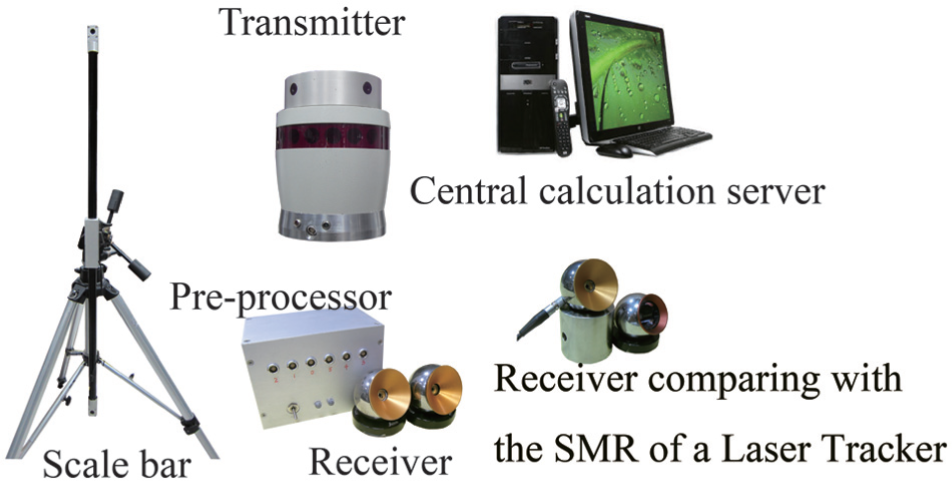
The components of the wMPS.
The mathematical solution model
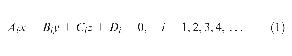
The two rotating laser planes bound to the head of a transmitter can be defined as two planes rotating around a fixed axis defined as a line at a uniform speed. For each transmitter, both the planes at the initial position and the fixed rotating axis are exactly known in the global coordinate frame. We use at least two such transmitters with different rotating velocities to define a measurement volume and then place a receiver representing the point to be measured in this measurement volume. Then, at least four rotating planes of the transmitters would intersect at the point, that is, the receiver (see Figure 2(b)). Then the coordinate of the point can be calculated by a system of linear equations using the least square method 52
where
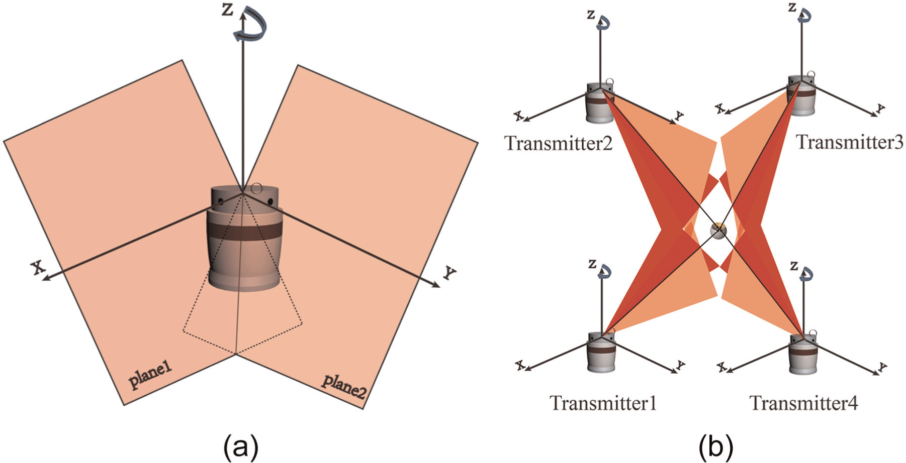
(a)The definition of the local frame on a transmitter and (b) the measurement model.
For simplification, we define a local coordinate frame for each transmitter. The concrete definitions in the local frame are as follows: The z-axis is the rotation axis. Origin is the intersection of the rotation axis and laser plane 1 at the initial position. The x-axis through the origin is on plane 1 and perpendicular to z-axis. The y-axis is determined according to the right-hand rule (see Figure 2(a)). The planes for each transmitter are defined in this local coordinate frame. If the transformation between any two transmitter’s local frames is known, and all the planes intersect at a point represented by the receiver, then we can solve for the point by the system of linear equation (1). In Figure 2(b), each rotating plane provides a time value which starts from the initial position when sweeping over the receiver. Each time value multiplied with the corresponding velocity identifies a virtual plane which goes through the receiver, and each virtual plane constructs an equation as a system of linear equation (1).
The adjustment calibration
The system measurement requires the locations of all the transmitters’ local coordinate frames to be known to the system. This is achieved through an internal calibration procedure, known as bundle adjustment, 53 which forms part of the setup procedure. Bundle measurements are recorded as a well-defined objects moved throughout the system’s measurement volume. The relative positions and orientations of the transmitters’ local coordinate frames are then determined by the central server using an advanced algorithm that repositions the transmitters to minimize intersection errors at all bundle points. The absolute coordinates of the transmitters’ locations are calculated through the use of a calibrated scale bar (see Figure 3).
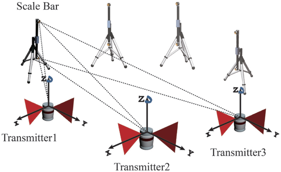
The calibration procedure of the wMPS.
The accuracy assessment of the wMPS
To verify the positioning accuracy of the wMPS, an experimental setup using a laser tracker for comparison is shown in Figure 4.
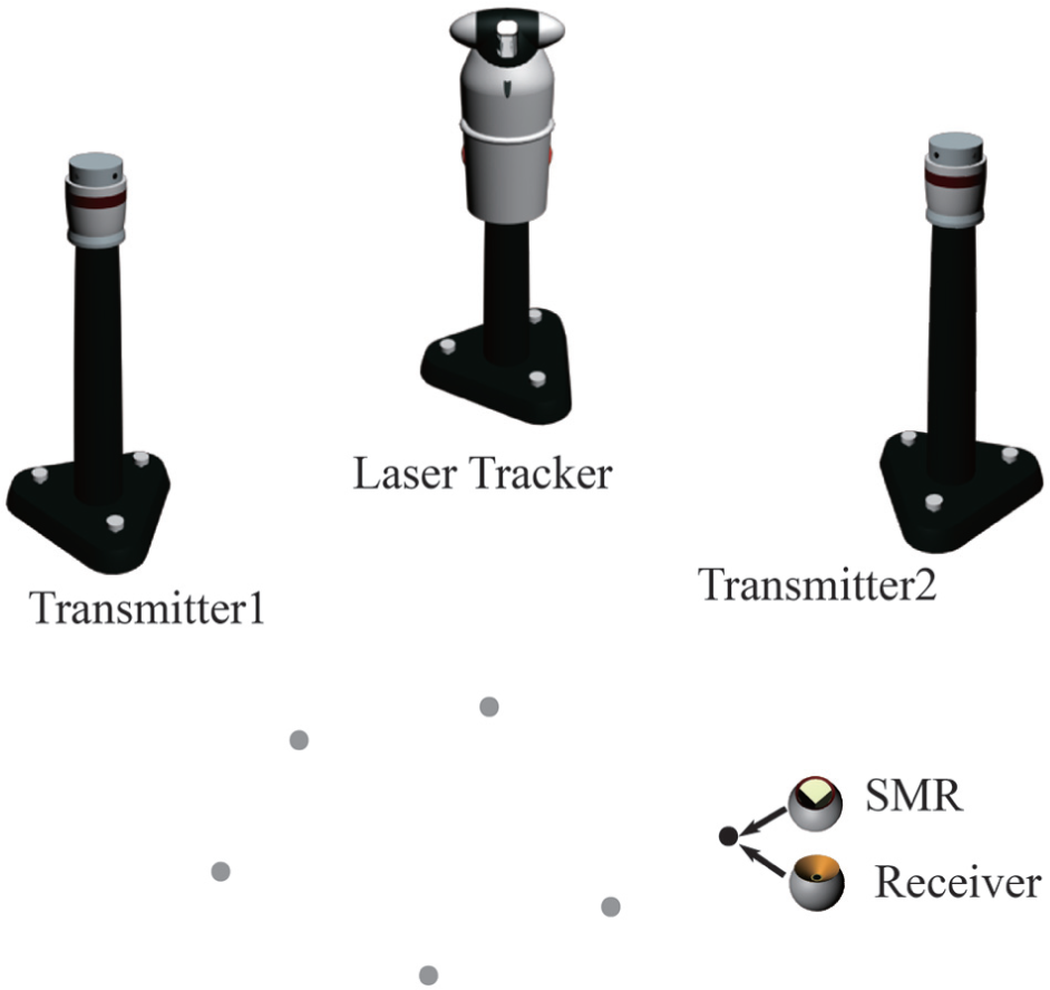
The schematic of the experimental setup to compare the accuracy of the wMPS with that of the laser tracker.
The two transmitters in Figure 4 are about 6 m apart. The laser tracker is placed at about the middle spot of the two transmitters for comparison. The transformation from the coordinate frame of wMPS to that of laser tracker can be calculated by acquiring at least three 3D (three-dimensional) point correspondences measured by both the wMPS and the laser tracker.54,55 We sample some points represented by black dots in front of the two transmitters in Figure 4. The coordinates of the points are acquired in this measurement volume by both the wMPS and the laser tracker; they are listed in Table 1.
Data comparison between the laser tracker and the wMPS.
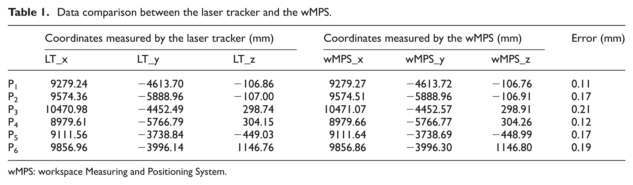
wMPS: workspace Measuring and Positioning System.
For each row started with P i , i = 1,2,3,4,5,6, the data under the column header “Error” are calculated by
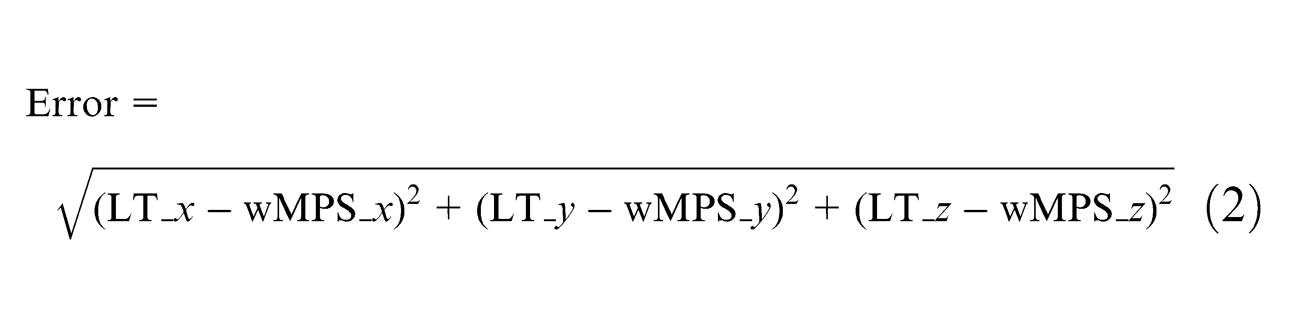
that is, the difference between the nominal provided by the laser tracker and the actual provided by the wMPS. We use the difference to measure the accuracy of the wMPS. The smaller the difference is, the better the accuracy would be.
We see from the data under the column header “Error” that the maximum error is 0.21 mm and the minimum is 0.11 mm. Adding these errors together and dividing them by 6, we get the average 0.16 mm. That is to say, the accuracy of the wMPS approximately lies in the interval 0.1–0.2 mm. If we could transfer the accuracy 0.1–0.2 mm to a robot’s absolute positioning, that would enhance the positioning capability of a robot markedly. In fact, there are factors that may have deteriorated the data. For example, the point the SMR represents is not the one the receiver represents because of the eccentric error in receivers, exchanging the targets, that is, the SMR and the receiver, may import errors, and the absolute orientation error between the wMPS frame and the laser tracker frame is another main error source. Even then, the comparison results show that the wMPS has the capability to be the external metrology system for improving the absolute positioning accuracy of robots.
The validation of the wMPS for a robot positioning
The experimental setup
From the experiment in section “The accuracy assessment of the wMPS,” we know that the accuracy of the wMPS is sufficient to be used for a robot’s positioning. Hence, the key to the improvement of a robot positioning is left up to how well the wMPS can guide a robot in the wMPS frame. An experiment would suffice to demonstrate it. From any reasonable initial position, we let the robot’s end-effector whose orientation is fixed move to a specific coordinate set by the wMPS and keep correcting the error between the desired and actual position until it is smaller than the accuracy of the wMPS. Then, let the laser tracker provide the actual distance the robot’s end-effector moves through. The nominal distance is calculated using the initial position and the specific position set by the wMPS. The error between the desired and actual distances can be used to assess the performance of the guidance. The experimental setup is shown in Figure 5.
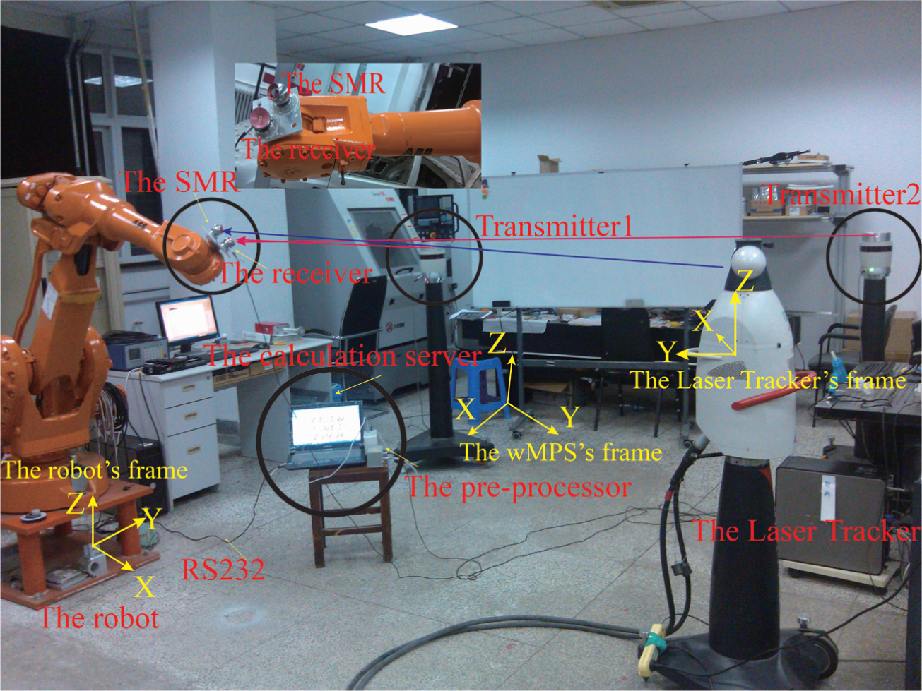
The experimental setup to assess the guidance of the robot by the wMPS.
At the initial position of the robot’s end-effector, we let the laser tracker record the coordinate of the SMR, written as

the actual distance is
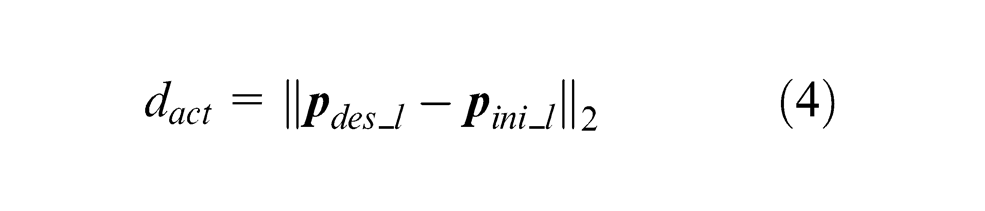
Then, we use
The process is illustrated in Figure 6. As shown in the figure, the laser tracker is like a ruler to provide the actual distance the robot moves through. First, we keep correcting the robot, until the difference between the actual and the desired position lies in the accuracy of the wMPS. Second, we use the laser tracker to provide the actual distance the robot moves through and then compare the actual distance with the nominal one to assess the performance of the guidance. Several additional such guidance in different directions would be enough to evaluate the guidance.
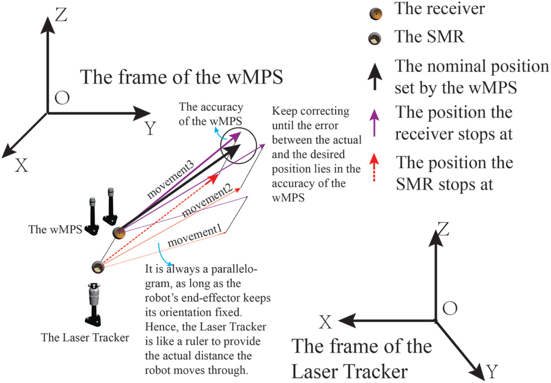
The illustration on the assessment of the guidance.
The experimental results
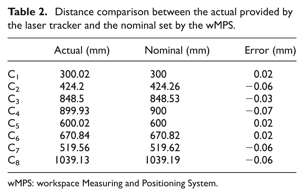
Fixing a position as the origin, we arbitrarily set several desired positions. Using the method in section “The experimental setup,” we acquired several couples of distances. They are listed in Table 2.
Distance comparison between the actual provided by the laser tracker and the nominal set by the wMPS.
wMPS: workspace Measuring and Positioning System.
In Table 2, for each row starting with Ci, where i = 1, 2, 3, 4, 5, 6, 7, 8, the number under the column header “Error” is calculated by

where the Actual represents the distance provided by the laser tracker, the Nominal represents the distance set by the wMPS. In each row, the Actual and the Nominal construct a distance couple denoted as Ci, where i = 1, 2, 3, 4, 5, 6, 7, 8. For example, the 300.02 and 300.00 construct C1, the corresponding error calculated by equation (5) is 300.02 – 300.00 = 0.02.
The nominal distances are arbitrarily given within about 1000 mm. The laser tracker records the actual distances that the robot moves through after the wMPS stops correcting. Under the column header “Error,” the errors between the actual and nominal distances are listed. The errors are calculated using equation (5). Obviously, the distance errors are all better than 0.1 mm. That is to say, the wMPS guides well.
The reason for these results is that the corrective movements of the robot are convergent. To explain the convergence, we deduce the model in section “The experimental model.” Then a more complicated model about the orientation or pose convergence is presented in section “Convergence model for orientation.”
The experimental model
There are three frames in the experiment depicted in Figure 5 of section “The experimental setup,” namely, the wMPS frame, the laser tracker frame, and the robot frame.
First, we prove that it is unnecessary to find the relationship between the wMPS and the laser tracker frame in this experiment.
Assume that there are two 3D point correspondences illustrated in Figure 7. The points with the subscript w are in the wMPS frame, and the points with the subscript l are in the laser tracker frame. It should be noted that
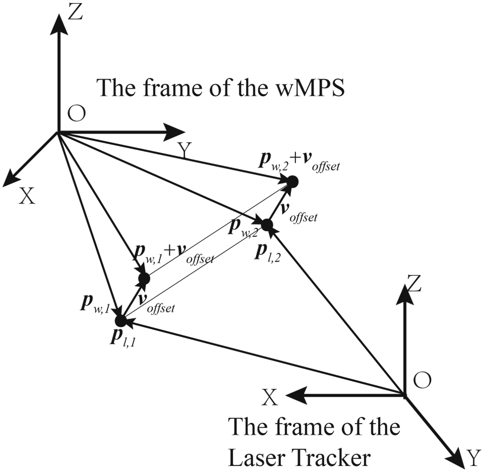
The distance is unchanged in either frame.
We set the points

where
Let equations (6) – (7), we have
The two-norm of equation (8) is
Based on the norm-preserving characteristic of a rotational transformation, we have
adding a offset
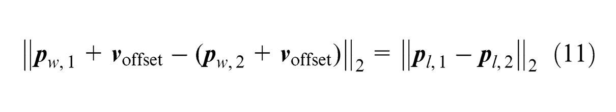
where
From equation (11), the rotational matrix and the translational offset do not affect the distance calculation. So it is unnecessary to find the relationship between the wMPS frame and the laser tracker frame in our experiment.
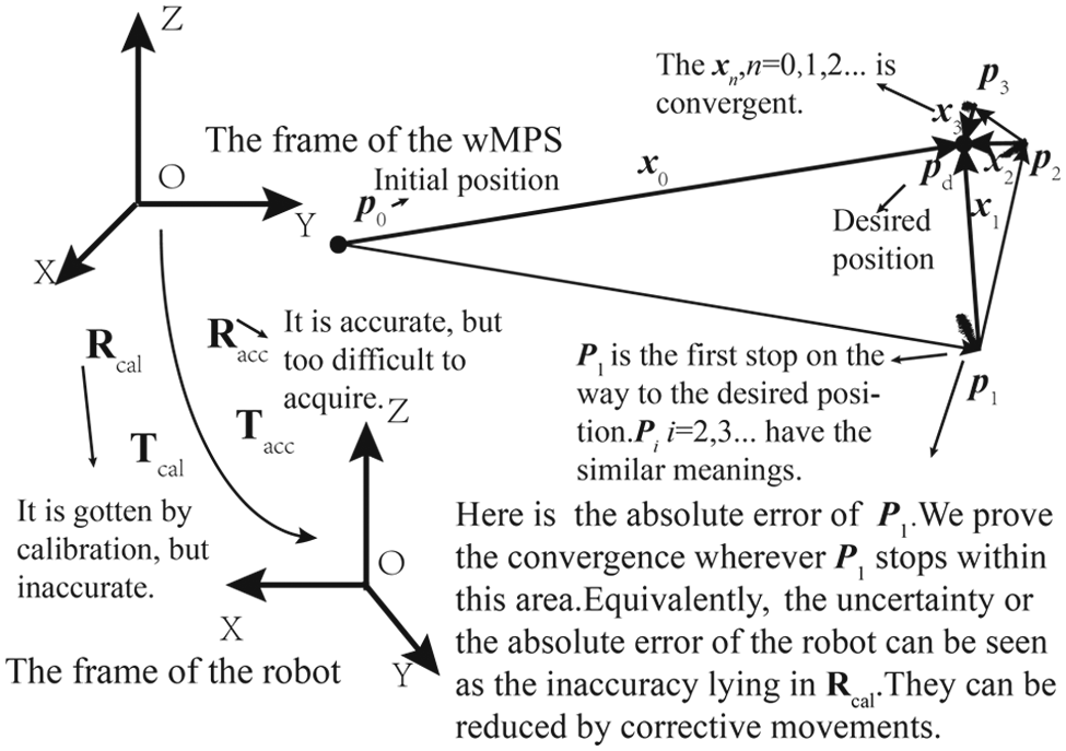
Second, we say that there is convergence throughout the guidance and explain that it is unnecessary to find the extremely accurate relationship between the wMPS and the robot frame. The construction of the convergence expression is illustrated in Figure 8.
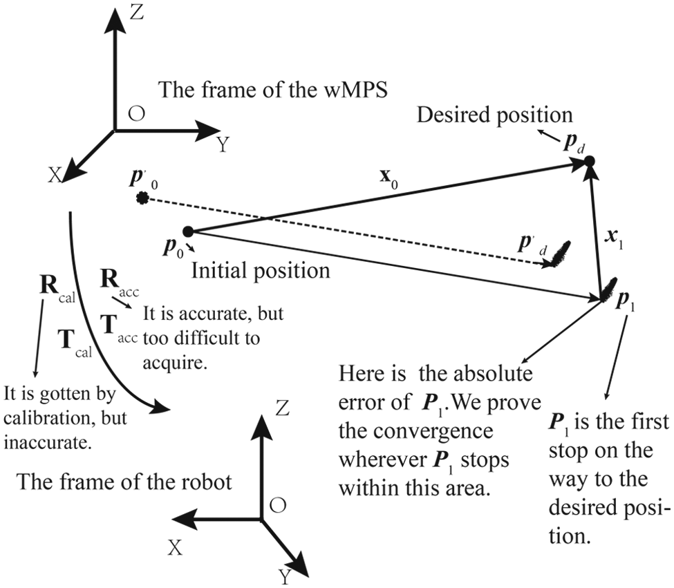
The construction of the convergence expression.
As shown in Figure 8, let the accurate relationship between the wMPS frame and the robot frame be
if
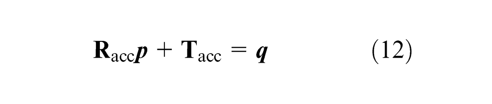
then
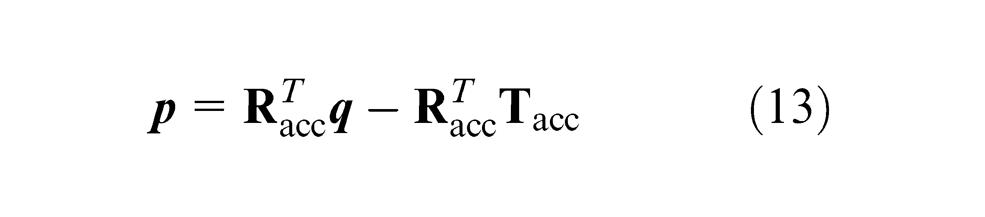
where
We construct the relationship between

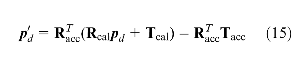
Actually, the robot moves from its physically initial position
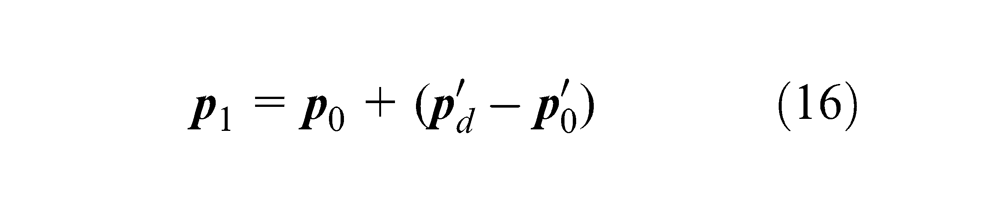
where
Letting equations (15) – (14) substitute the
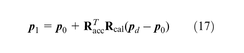
Multiplying −1 and then adding
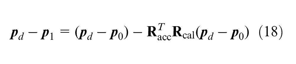
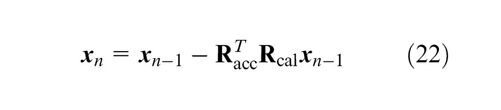
Now, let

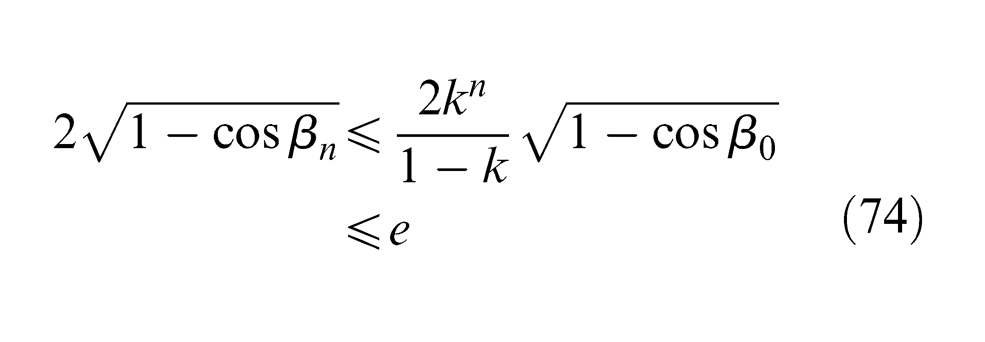
Following the form, we have

where
Defining

we get
The construction of the sequence of movements.
Now, we prove that
By equation (22), we let n = 1, 2
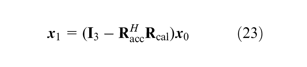

where
In equation (24), substituting the right-hand side of equation (23) for
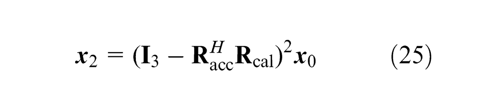
Iteratively, constructing the relationship between

Define
Hence, equation (26) can be rewritten as

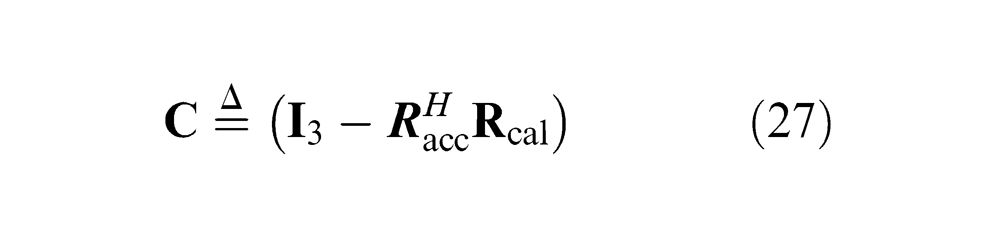
Now, for arriving at
where
In equation (27), substituting the right-hand side of equation (29) for
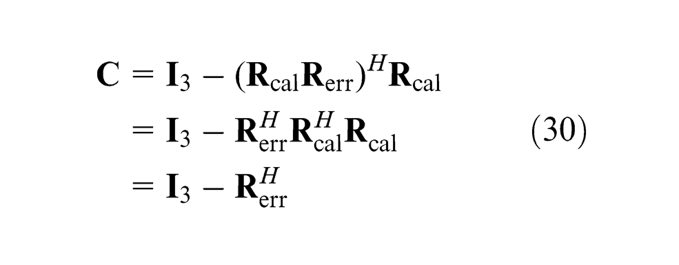
One verifies that
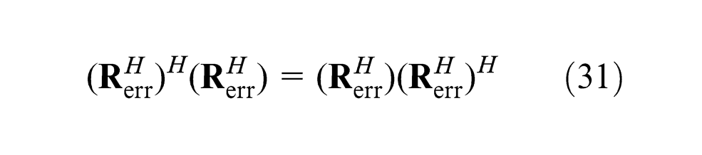
By the definition of a normal matrix that any matrix
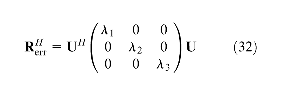
where
Lemma
For any
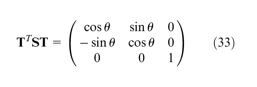
and the eigenvalues of
By the Lemma, letting α be the angle deduced from


then

and
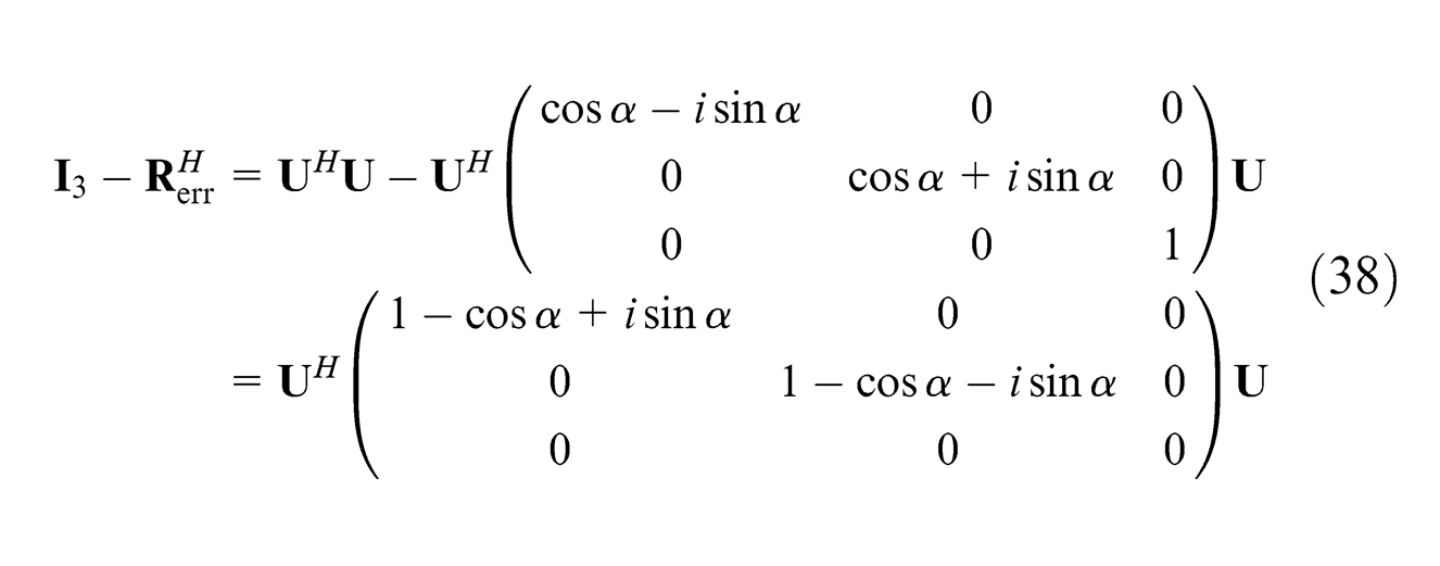
In equation (30), substituting the right-hand side of equation (38) for
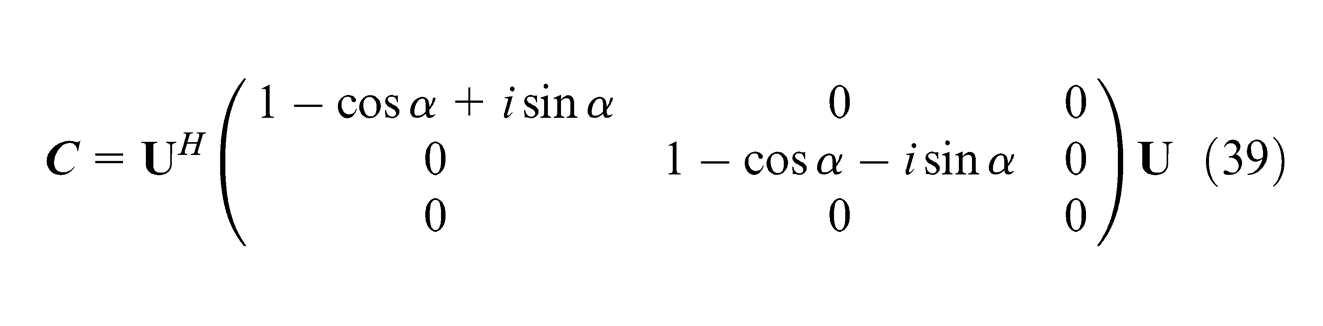
Recalling equation (28) here (
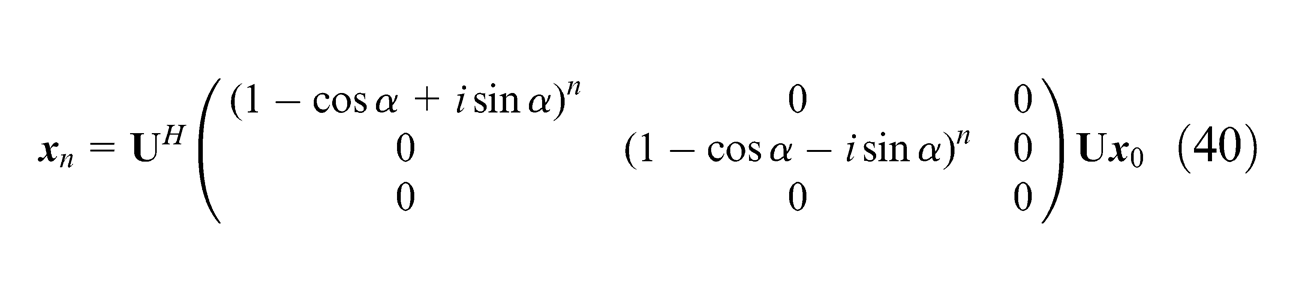
The two-norm of equation (40) is
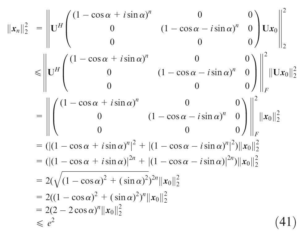
where the

Since
that is
that is
where
From the analysis above, we see that the whole guidance process is convergent as long as the rotational angle deduced from
Actually, the physical meaning of
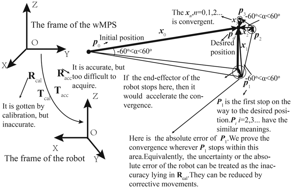
The physical meaning of α and the explanation of reducing the absolute error of the robot by convergence.
Moreover, we highlight that the point cloud within each circle represents the absolute error of the corresponding position, and the existence of the absolute error does not affect the convergence. In Appendix 3 where the method of acquiring
Now we continue to deduce equation (41) as follows
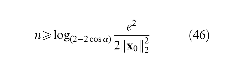
where
The relationship among the relevant variants through the movements with the orientation fixed.
From Figure 11, we conclude as follows: (1) As the absolute value of
By the above theoretical analysis, we draw the sectional conclusion that (1) there is convergence throughout the guidance with the orientation fixed; (2) the convergence is not relevant to the translational offset in the relationship between the wMPS frame and the robot frame, it is only relevant to the rotational matrix between the two frames; and (3) a sharp estimate of relationship between the wMPS frame and the robot frame is unnecessary in our system.
Convergence model for orientation
Before deducing the model, we present how to denote the same rotation in different frames, as illustrated in Figure 12.
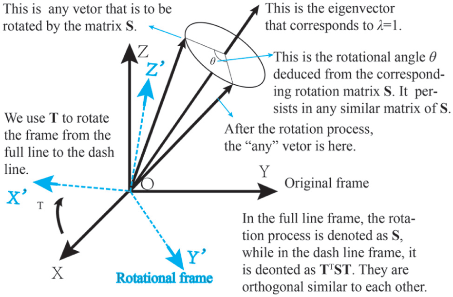
The matrices of the same rotation in different frames are orthogonally similar to each other.
There are two frames we are concerned about in our system. One is the wMPS frame and the other is the robot frame. The rotation is executed in the robot frame; however, the orientation of the end-effector is measured in the wMPS frame. Hence, we need to shift our perspective to the robot frame when we are concerned about the execution of the rotation, shift the perspective to the wMPS frame when we are concerned about how far it is away from the desired orientation.
When we shift from the wMPS frame to the robot frame, we use the inaccurate
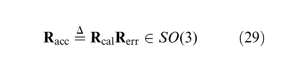
We recall the definition of the accurate rotation matrix in equation (29)
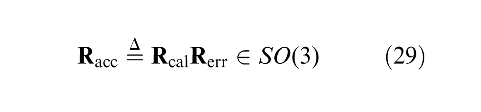
where
If we want to execute a rotation represented by

where
To shift the perspective back to the wMPS frame, we have
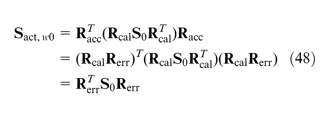
where
Now, the wMPS measures once and tells that one more rotation represented as

Equivalently, we have
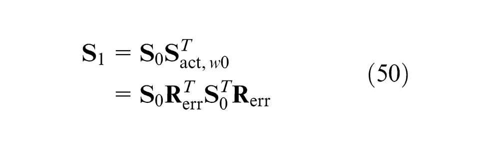
Repeating the process from equations (47) to (50), we have
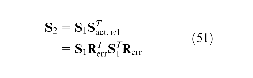
where
Continuing with the rotation process, we get the general equation as follows
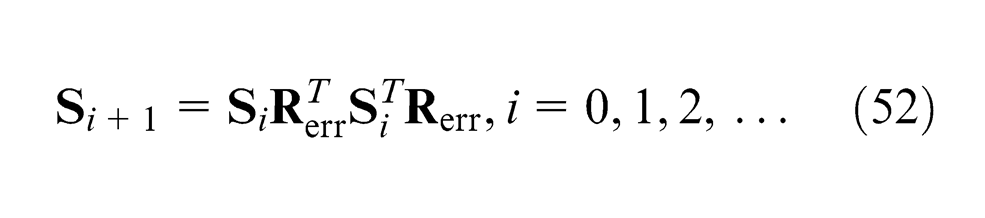
Simply analyzing equation (52) that if the sequence
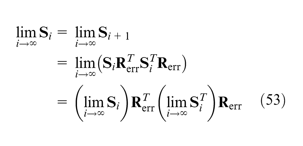
One concludes that
where
Whether the sequence of rotations represented by equation (52) is convergent depends on the coefficient
Definition
Let
for all x, y in X.
Contraction mapping theorem
Let
Based on the contraction mapping theorem and the Lemma, we conclude our problem in mathematics as follows.
Set
where
Define
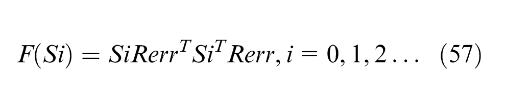
Find all possible
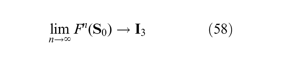
holds for all
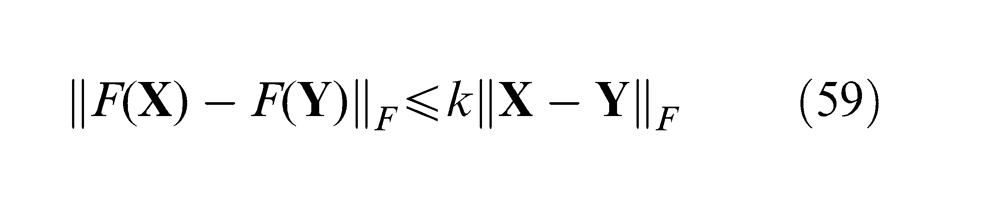
Aiming at proving equation (58), we should find the range of
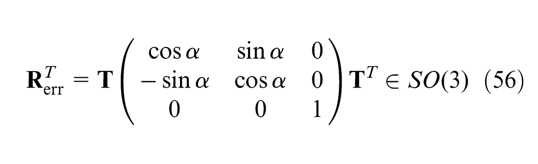
For any special orthogonal matrix
where
Equivalently, we conclude
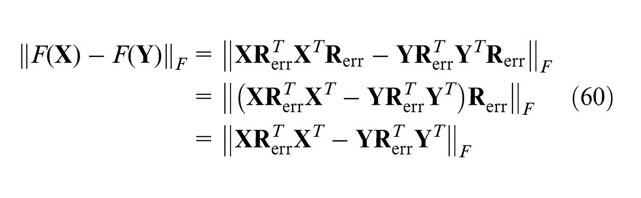
where the last equality sign is based on the norm-preserving characteristics of a rotation matrix.
Continuing with equation (60), we have
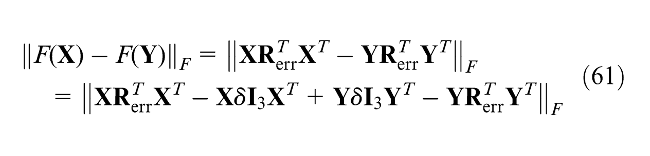
where
Continuing with equation (61), we have
where
Continuing with equation (62), we have
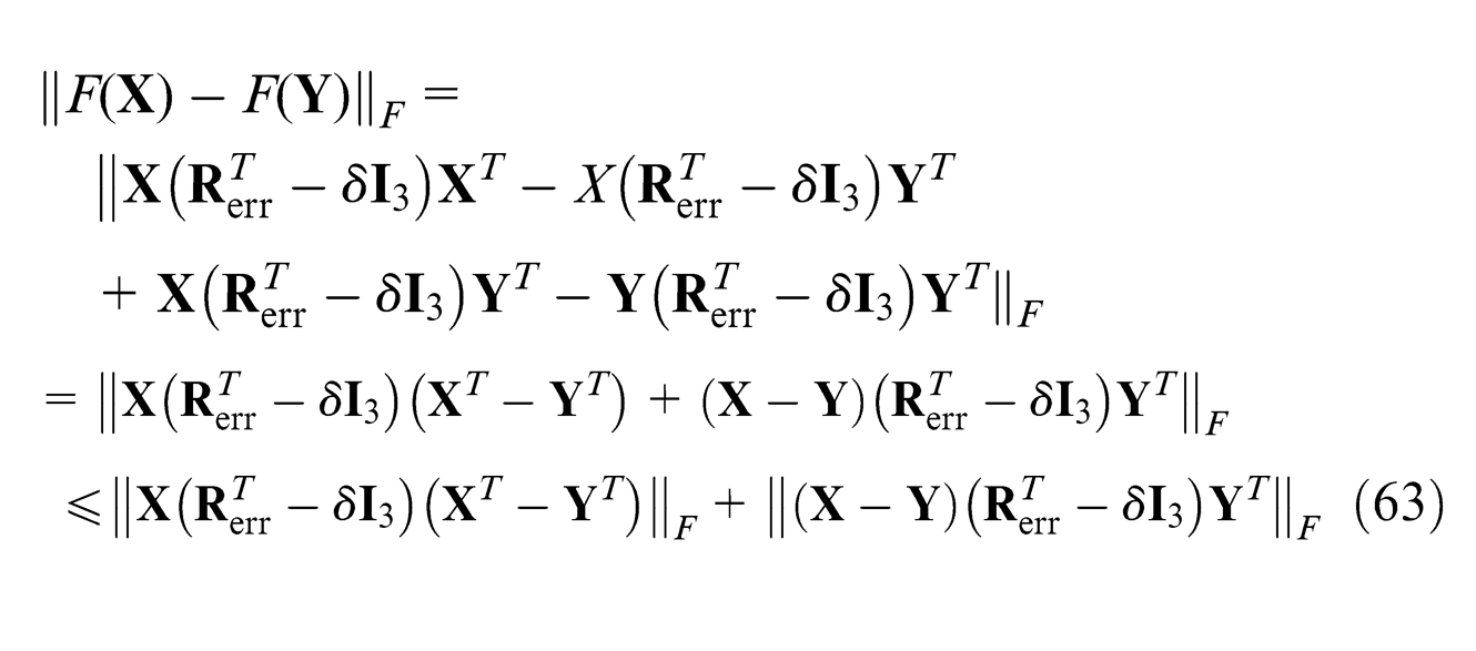
where the inequality sign is based on Minkowski inequality. 56
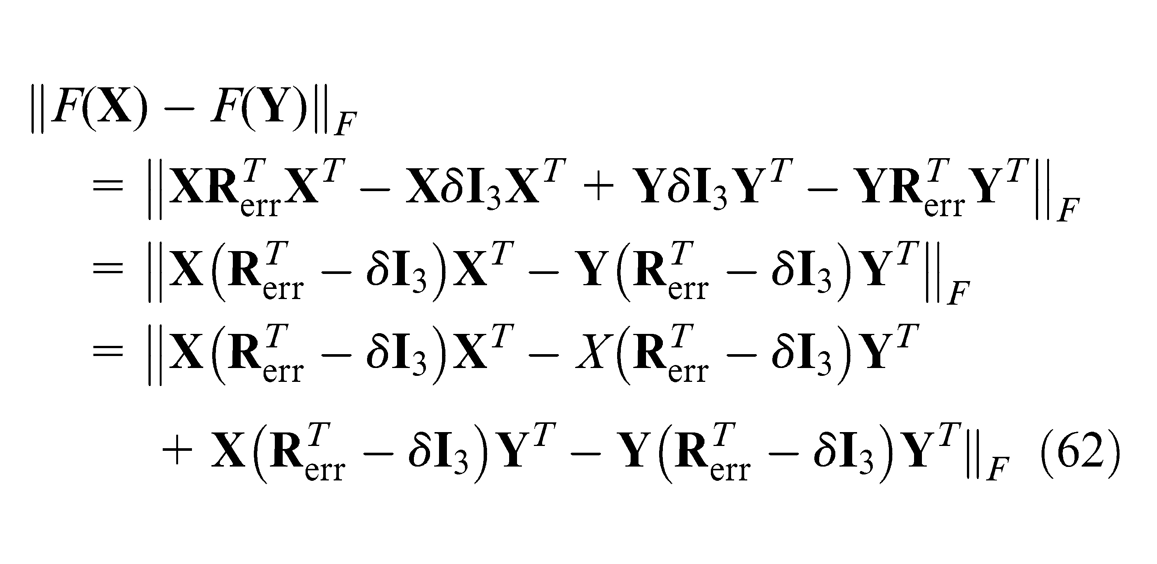
Continuing with equation (63), we have
where the first equality sign is based on the norm-preserving characteristic of a rotation matrix, and the second inequality sign is based on Cauchy–Schwarz inequality. 56
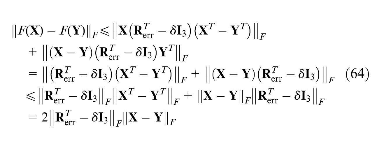
Moreover, we have
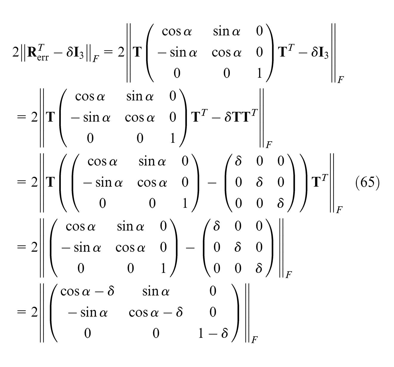
where
Substituting the result of equation (65) for the
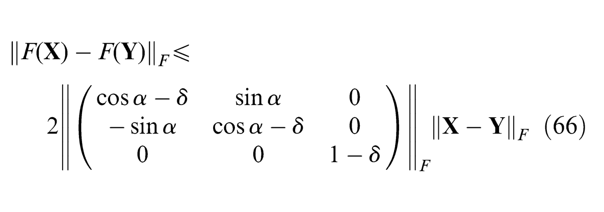
Comparing with inequality (59) and by the contraction mapping theorem, we need
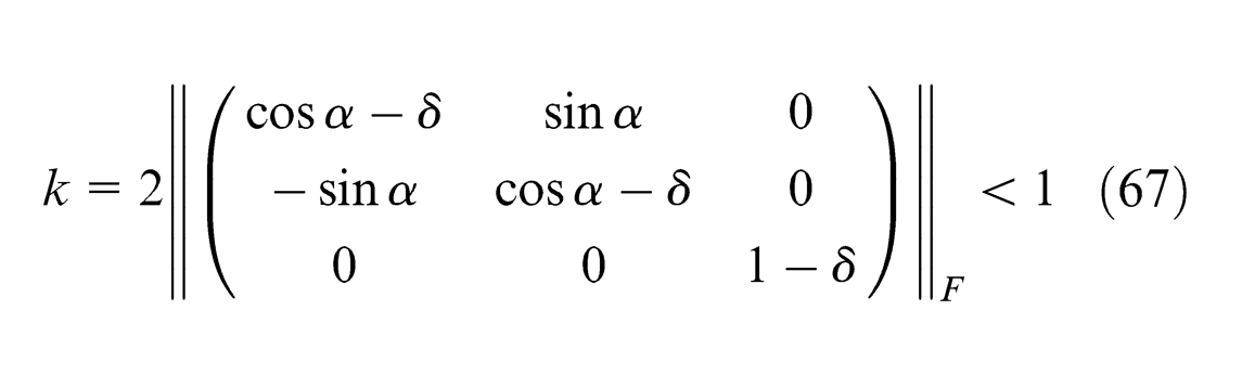
Taking the square of equation (67), we obtain
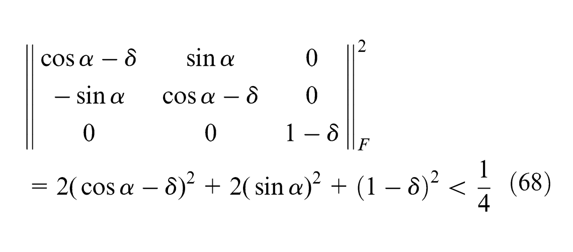
Expand and collect inequality (68)
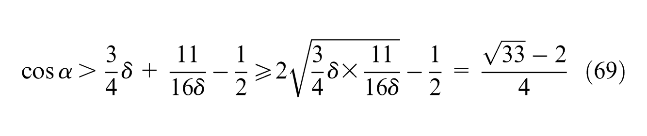
where if and only if
Finally, we have
Now, we present error estimate formula of the contractive mapping
Moreover, we have
where
Also, we have
where
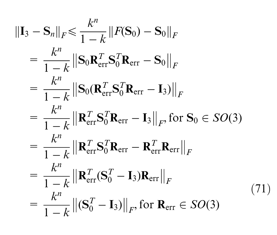
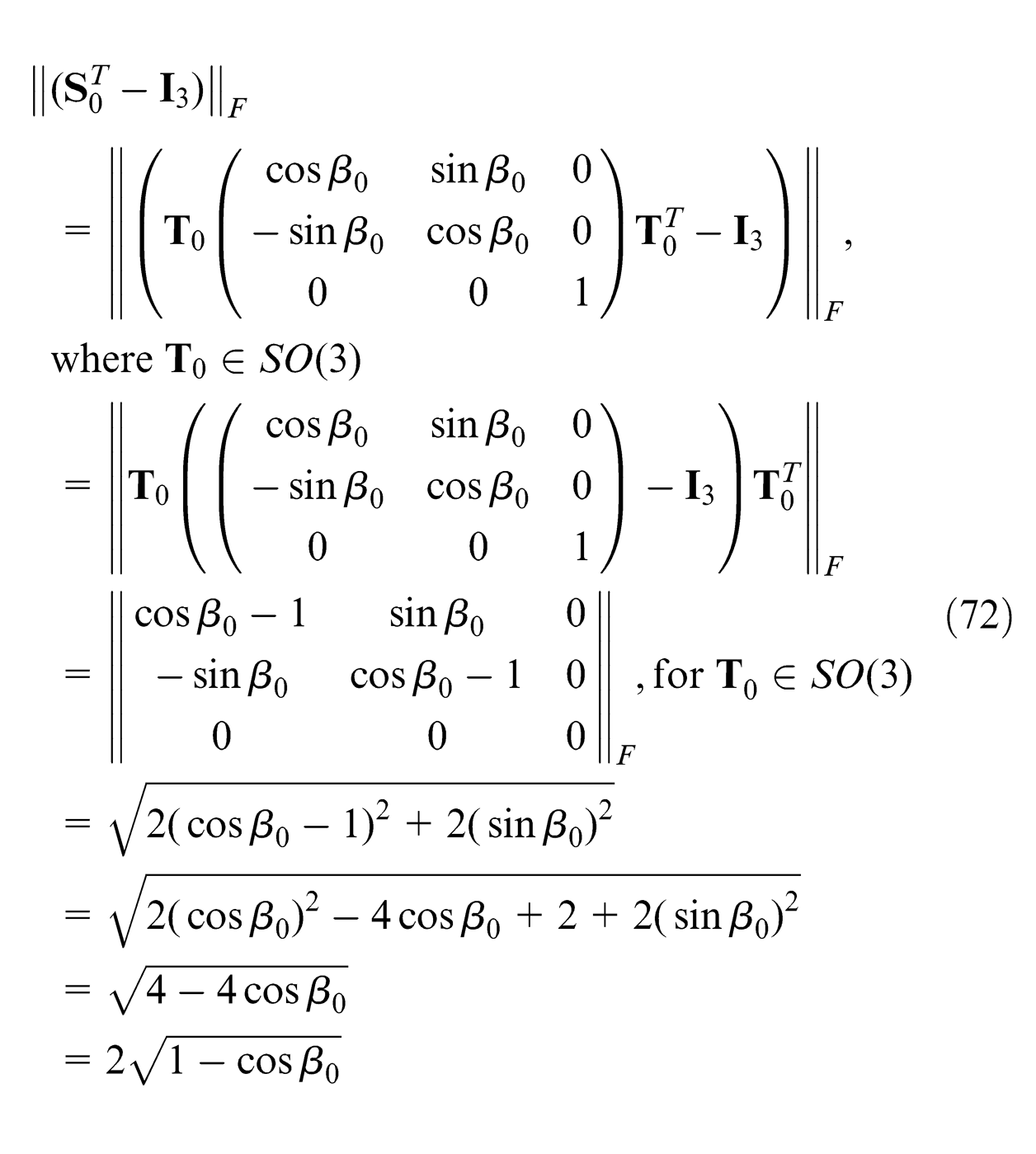
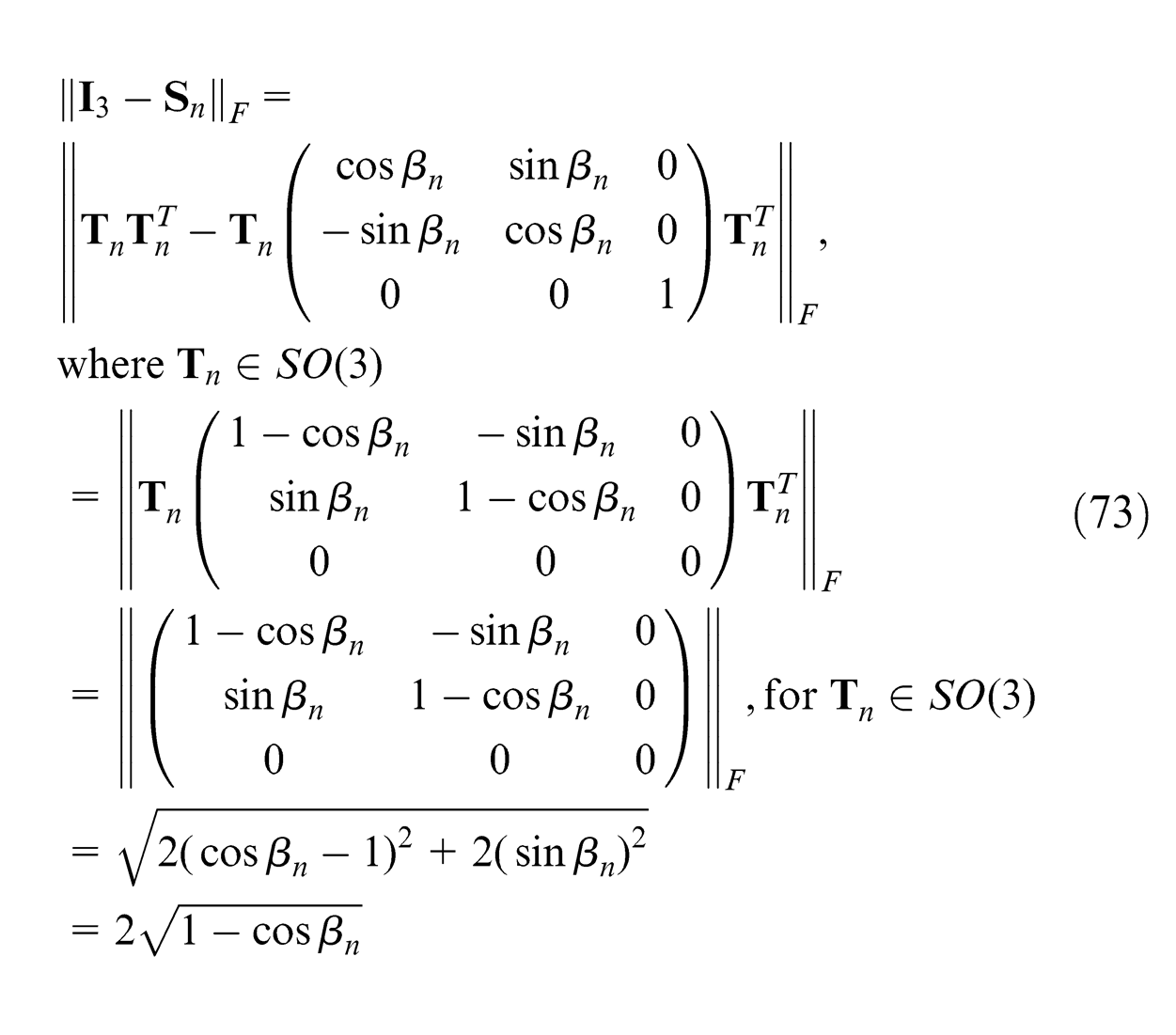
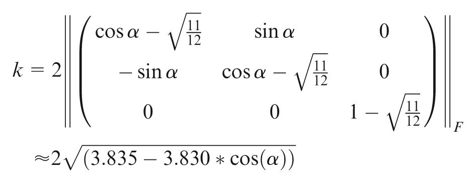
Substituting the results of equations (72) and (73) for
where
We give
where
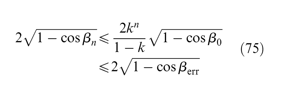
By equation (75), we get
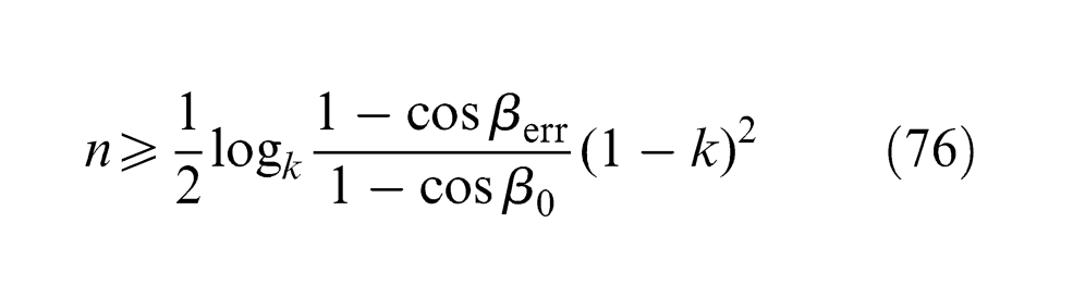
where
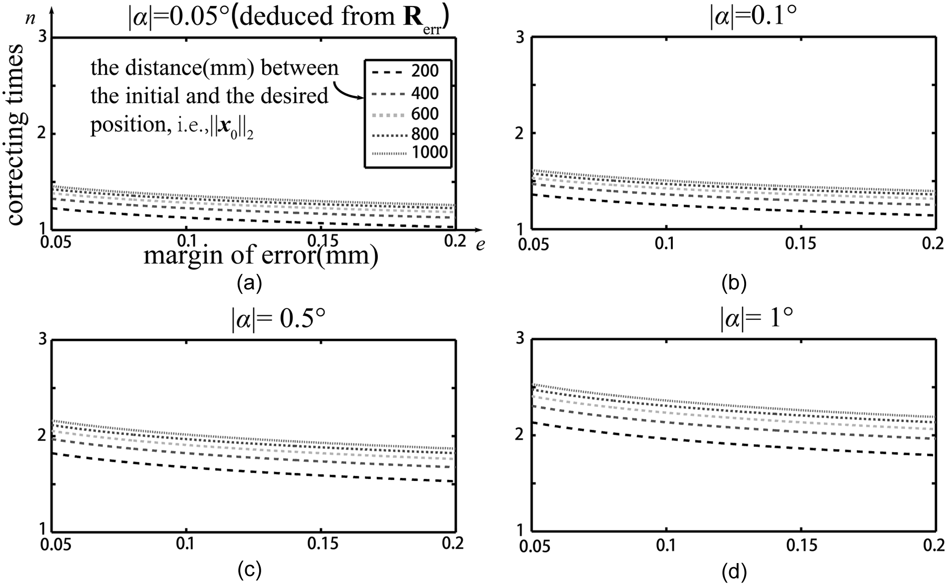
Hence, we get the relationship among the correcting times
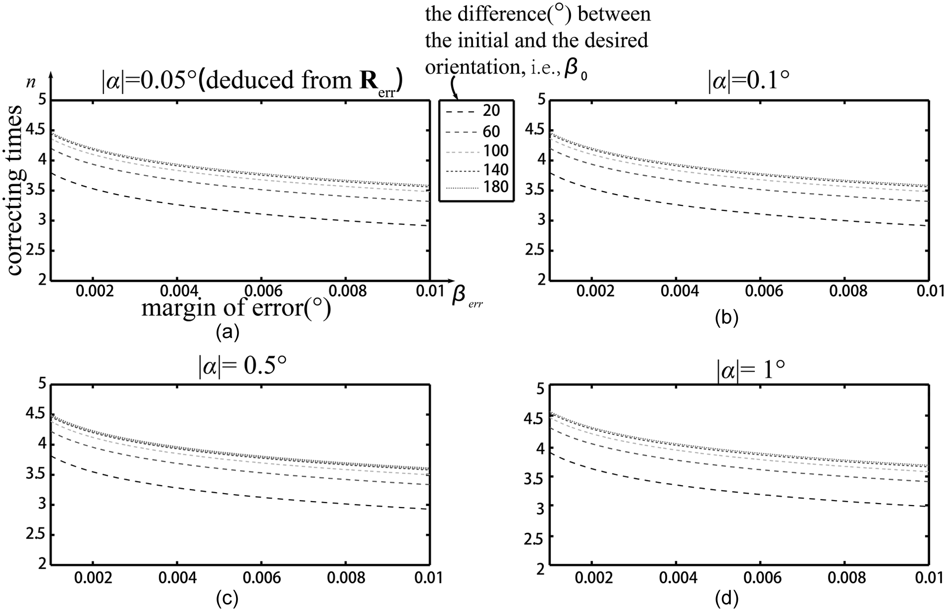
The relationship among the relevant variants through the movements considering orientation only (a)The situation fixing α at 0.05°, (b)The situation fixing α at 0.1°, (c)The situation fixing α at 0.5° and (d)The situation fixing α at 1°.
From Figure 13, the following is observed: (1) As the absolute value of
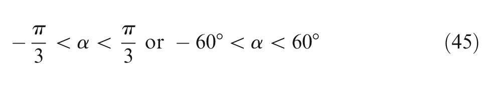
To sum up, we recall the previous conclusion about the position convergence represented by equation (45)
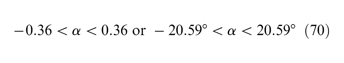
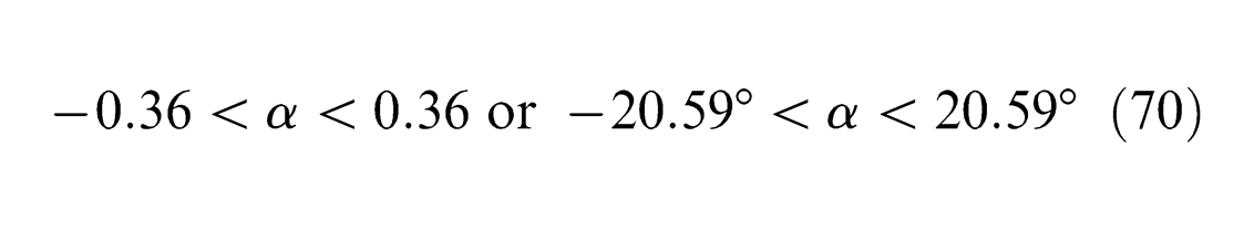
the conclusion about the orientation convergence represented by equation (70)
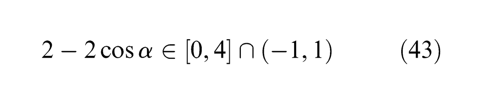
Hence, the intersection of the ranges of
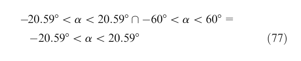
is the minimum condition we need for a high accurate positioning of an industrial robot, including position and orientation. Comparing with the general
Conclusion
In summary, we first introduce the wMPS featuring the capability to provide a high measuring accuracy and efficiency in a large measuring range and then we carry out the experiment validating that the wMPS can improve a robot’s absolute positioning accuracy by changing the reference frame to the wMPS. To explain the convergence of the corrective movements when guiding the robot’s end-effector in the wMPS frame, we deduce the model which not only tells that there exists a relatively low requirement for assuring the convergence but also tells the relationship among the correlating factors in the correcting process. The model also reveals that the absolute positioning accuracy of a robot’s end-effector can depend on the external metrology system because of the convergence. In this article, the wMPS as an external metrology system can provide an accuracy of better than 0.2 mm for the industrial robot.
In our future work, some constraints under bad working conditions will be specially investigated, for example, the light-blocking problem in a robot-based fuselage alignment, the accurate cooperation among robots in the workspace of wMPS-based robot cell, the path planning problem, 57 and the layout of the wMPS for controlling the accuracy in interested areas.
Footnotes
Appendix 1
Appendix 2
Appendix 3
Acknowledgements
The authors would like to express their sincere thanks to the National Science & Technology Pillar Program of China and the National High-technology & Development Program of China for supporting this project. The comments from the reviewers and the editor are very much appreciated and the authors thank them for the same. The authors also acknowledge the vital contributions made by Jeanne Boren, Ye Sun and Xiuyun Liu, who gave instructive advices on the written English. Special thanks to Xiaoxia Yang, who was always willing to help during the research and provided many instructive advices.
Declaration of conflicting interests
The authors declare that there is no conflict of interest.
Funding
This research was supported by Key Projects in the National Science & Technology Pillar Program of China (2011BAF13B04) and the National High-technology & Development Program of China (863 Program, 2012AA041205).