
Abstract
Estimation of the temperature distribution in roll and strip is important for the modeling of rolling process. A number of numerical and analytical methods have been proposed in the literature for the estimation of temperature distribution in rolling. This work proposes a simplified and faster semi-analytical method. A finite element method code is used for the estimation of friction and plastic deformation powers based on partially converged solutions. These powers form inputs to analytical temperature prediction modules. The heat partition between rolls and strip is accomplished by matching the interface temperatures obtained from the temperature modules of strip and roll. The proposed method is validated from the experimental results available in literature, and a good agreement is found. Some parametric study has been carried out based on the proposed method.
Keywords
Introduction
Rolling is one of the most widely used metal forming processes. The flat rolling for reducing the thickness of the strip is very commonly used in industry, and its mathematical modeling has attracted the attention of a number of researchers. Mathematical modeling of rolling process requires the knowledge of temperature distributions in the rolls and the strip. The proper estimation of temperature is important even for cold rolling because it greatly influences the lubricant behavior and roll wear characteristics. 1 Sometimes, the mechanical properties and microstructure of the strip may be affected due to temperature even in cold rolling. 2 Measurement of temperature in cold rolling can be useful for inverse determination of friction and strip material parameters, provided a theoretical model for the estimation of temperature is available. For example, recently, Yadav et al. 3 proposed that the performance of lubricants can be assessed based on the temperature measurement. Yadav et al. 4 also presented a methodology for inverse determination of strip material parameters and friction based on the temperature and forward slip measurements.
There are a number of methods for the estimation of temperature in rolling. The prominent among them are finite element method (FEM) and finite difference method (FDM). Some analytical solutions have also been proposed, which invariably are in the form of summation of infinite series containing Bessel functions. These methods are useful for an accurate analysis, but often, the designer or control engineer is interested in a fast estimate by sacrificing the accuracy to some extent. This work proposes an approximate method for the estimation of temperature distribution in the roll and the strip in a steady-state cold strip rolling. The proposed method is simpler and faster compared to available methods in literature.
A brief review of the earlier attempts in the estimation of temperature in rolling and in the system of two sliding/rolling bodies is as follows. DesRuisseaux and Zerkle 5 proposed a solution of problem, in which a heat source acting on a band moves on a cylindrical body. The Laplace transform method has been used to solve two-dimensional transient heat conduction equation in r–θ coordinate system. No results were shown for any typical rolling problem. Fischer et al. 6 proposed an analytical model for the temperature distribution in a wheel–rail system considering friction. An asymptotic model of work roll heat transfer in strip rolling was proposed by Johnson and Keanini. 7 A good agreement of the predicted results with previously published experimental results was obtained. However, the focus of this article is on thermal analysis, and no guidelines have been provided for carrying out deformation analysis. Komanduri and Hou 8 developed an analytical model to analyze the heat partition factor and the temperature distributions in the sliding system. They considered the rise in temperature distribution mainly caused by frictional heat source at the interface. They determined the heat partition factor by matching the temperature at the interface of two sliding bodies.
Pauk and Zastrau 9 solved two-dimensional rolling contact problem involving friction heating. Nonlinear problem was solved iteratively. The solution presented by the authors is not directly applicable to strip rolling process. Fischer et al. 10 proposed an approximate solution for plane strain hot rolling problem and compared the temperature distribution in roll with finite element results of Sun et al. 11 and Hwang et al. 12 The numerically calculated temperature field deviates from the analytical solution by less than 10%. However, a model for the estimation of temperature distribution in strip has not been proposed in this work. Thermo-mechanical-induced residual stresses of work rolls have also been modeled in hot rolling problem. 13 Temperature in rolls is estimated by an analytical model by considering two bodies in contact together.
A complete solution of the temperature distributions in rolls and strip considering the plastic deformation of strip is the need of the hour. For achieving this goal, FEM and/or FDM are the most attractive numerical tools. A number of researchers have used these tools for the complete solution of the rolling problem. Tseng 14 estimated temperature distribution in roll and strip using a finite difference scheme. Several simplifying assumptions have been made. Input data for heat generated and frictional heat are obtained by direct measurement of power. It is assumed that 6.5% of the 90% of total power is dissipated as friction heat at the interface. In another study by Tseng et al., 15 to study the effect of various cooling arrangements on the thermo-mechanical responses on the roll, a finite difference model was used for finding out the temperature distribution in roll and strip, while heat generated due to plastic deformation and friction was obtained by a one-dimensional model based on the slab method. Wilson et al. 16 estimated temperature distributions at the roll–strip interface in cold rolling using an FDM. Several simplifying assumptions have been made. The authors found the local value of heat transfer coefficient at the interface by matching the surface temperature of both roll and strip. Luo and Keife 17 obtained temperature distribution in roll and strip for foil rolling using an FDM. The authors coupled the developed thermal model with existing mechanical model to evaluate the roll-flattening and frictional effects. They found that the net heat input to the roll decreases with increase in the roll temperature, which results in the thermal equilibrium of the roll. Devadas et al. 18 and Chen et al. 19 used FDM for finding out the temperature distribution, but they used highly simplified procedure for finding out the heat generation in the roll bite.
Pietrzyk and Lenard 20 developed two finite element thermal models of the flat rolling. The first model presents a solution of steady-state convective diffusion equation neglecting heat transfer in the transverse direction and edge cooling. The second model omits the convective term and gives a solution for nonsteady-state problem. Both models are validated by in-house experiments. Both models can be used under specific conditions. In Hwang et al., 21 both deformation and temperature analyses have been carried out using FEM. An iterative scheme is adopted for metal flows and temperature in hot strip rolling. It is assumed that one half of the friction heat generated goes into the roll and the other half goes into the strip. Galantucci and Tricarico 22 carried out thermo-mechanical simulation of rolling process using FEM. However, detailed descriptions of the formulation have not been provided. Feng et al. 23 estimated the temperature field and thermal crown using a commercial FEM package, ANSYS.
Serajzadeh 24 proposed a mathematical model to obtain the temperature distribution in the hot rolling of steels. They showed that heat transfer coefficient at the interface and the rolling speeds are influencing factors for the temperature field within the work roll. Two-dimensional FEM model was used to predict flow stresses, microstructure and mechanical properties in warm rolling of low-carbon steel.25,26 Khalili et al. 27 used combined finite element and slab method to predict the thermo-mechanical behavior of work rolls during warm strip rolling. Chang 28 used the finite difference scheme coupled with the assumptions of a steady-state rolling condition and a nonuniform heat flux in the deformation zone to predict the work-roll temperature field and the resulting stresses. Phaniraj et al. 29 proposed a thermo-mechanical metallurgical model to estimate the temperature field and microstructural changes during hot strip rolling. Bagheripoor and Bisadi 30 studied thermo-mechanical behavior of aluminum strips in hot rolling using commercial FEM package ABAQUS. Serajzadeh et al. 31 presented two-dimensional FEM model coupled with unsteady-state heat transfer equations with time-dependent boundary conditions to predict the work-roll temperature distributions during continuous hot slab rolling process. Recently, Oznergiz et al. 32 used neural networks to obtain the temperature in hot rolling, but the method requires a lot of experimental data for training the network. An integrated thermo-mechanical model of thin slab direct rolling of Nb steel for hot rolling has been developed by Shahtout et al. 33 The model makes use of a number of empirical relations available in literature. The authors have not discussed the computational time issue in their article, but the predicted results match well with the experimental results.
It appears that FEM- and/or FDM-based model are successful for carrying out a complete analysis of strip rolling process, but these methods require a lot of computational time. This article proposes a computationally faster method. This article is organized as follows. Section “Proposed method” describes the proposed method. Section “Determination of temperature distribution by FEM” describes the estimation of temperature that was used for comparison. Results comprising validation and parametric study are discussed in section “Results and discussion.” Section “Conclusion” concludes this article.
Proposed method
In the proposed method, the mechanical deformation process of the strip is analyzed by FEM. The plastic deformation and friction power obtained by FEM code is used as input for the thermal analysis of roll and strip. There are separate modules for the estimation of temperature distributions in roll and strip. The heat partition between the roll and strip is decided by matching the average roll and strip temperatures at the interface. If the obtained strip temperatures are significant enough to alter the material properties, the deformation analysis needs to be carried out again. The temperature distribution is again estimated, and the analysis is stopped or further iterations are carried out depending on the temperature results. However, in most of the cold rolling problem, only one iteration of deformation and thermal analysis is enough.
Figure 1 shows a schematic diagram of the rolling process. Only upper half portion of the roll–strip is considered due to the symmetry of the problem. The plastic deformation is assumed to occur in the domain BGHC. It is assumed that 90% of the work in plastic deformation gets converted into heat, and all the frictional work gets converted into heat input at the roll–strip interface. At the interface of the roll and strip, heat transfer takes place. In this work, two modules are developed for obtaining the temperature distribution. One module finds the temperature distribution in the strip when the heat generation due to plastic deformation and due to friction is known. The other module estimates the temperature distribution in rolls when the heat transfer through the roll–strip interface is known. Actual heat transfer through the roll–strip interface is not known. Here, it is obtained by an inverse procedure such that both the modules predict the same average temperature at the interface of roll and strip. If Q is the total friction plus plastic deformation generated heat, the quantity λQ is assumed to pass to the rolls and (1 −λ)Q remains in strip. The value of partition factor λ is obtained to match the temperatures from both the modules. The modules are described in sections “Module for the estimation of temperature distribution in rolls” and “Temperature of strip.” It is assumed that the thermal contact resistance between the roll and strip is zero, and the exact matching of roll and strip temperatures is justified. This assumption has been employed by Komanduri and Hou 8 for analyzing the temperature distribution in the sliding systems and by Wilson et al. 16 for analyzing the temperature distribution in dry rolling. The methodology can be easily extended to the case of nonzero thermal contact resistance, where the heat flow can be taken as directly proportional to temperature difference between the roll and strip and inversely proportional to thermal resistance between the roll and strip. However, this requires the incorporation of thermal behavior of surfaces and lubricant.
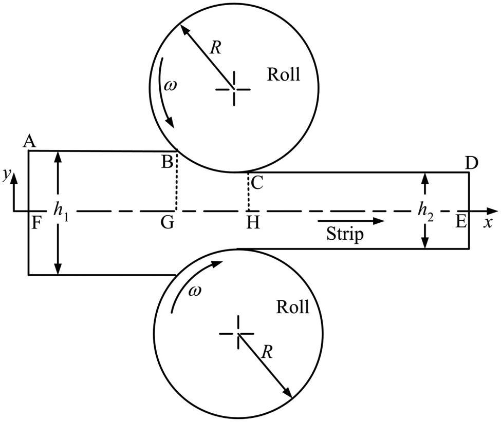
Schematic general view of the rolling process.
The algorithm of the whole procedure is as follows.
Step 1. Carry out the deformation analysis using FEM-based code.
Step 2. Assume that all the frictional heat goes into the roll and 90% of plastic deformation power goes as heat into the strip. A part of frictional heat may go into the strip as well depending on the relative temperature difference between roll and strip, but it is better to begin the analysis by assuming that the roll is colder than strip due to forced or natural cooling, causing entire frictional heat to flow into the roll. Assumption of 90% of plastic deformation going as heat and remaining to increase the internal energy of metal is commonly taken in metal forming. 26
Step 3. Carry out thermal analysis of roll and strip. Use modules for the estimation of roll and strip temperatures.
Step 4. If average temperatures of the strip and roll are equal at the interface, go to Step 7.
If the average temperature of the strip at the interface is less than average temperature of roll, then go to Step 5.
If the average temperature of the strip at the interface is greater than average temperature of roll, then go to Step 6.
Step 5. First assume that entire friction heat goes into strip. If the average temperatures of roll and strip at the roll–strip interface are same, analysis is completed; go to Step 7.
Otherwise, find out the optimal distribution of friction heat into roll and strip by any one-dimensional search scheme, for example, bisection method. 34 At the optimal distribution, average roll and strip temperatures will match at the interface. Go to Step 7.
Step 6. Assume that along with the friction heat, about 10% heat due to plastic deformation goes into roll. If the average temperatures of roll and strip are equal at the interface, go to Step 7.
Otherwise, if the temperature of roll is still lower, then increase the percentage of heat due to plastic deformation entering into the roll till the average roll and strip temperatures are equal at the roll–strip interface or average roll temperature is more than average strip temperature at the interface. If average roll and strip temperatures are equal, go to Step 7. If roll temperature is more than strip temperature, carry out one-dimensional search to find out the optimal amount of heat due to plastic deformation going into the roll. Go to Step 7.
Step 7. Record the temperature distribution of roll and strip. At the strip temperature obtained, find out the material properties. If the material properties are significantly different, go to Step 1 and carry out the next iteration with new material properties.
Else stop.
Module for the estimation of temperature distribution in rolls
A model is developed for finding out the steady-state temperature distribution in the roll. Temperature distribution for zero initial temperature is directly taken from literature.10,35 On this distribution, a constant temperature field is imposed based on an approximate analysis. Figure 2 shows the heat transfer in roll at steady state. Let the heat input be given at outer radius b in the zone of 2β angular displacement. Remaining outer surface of the roll is subjected to convective heat loss. The inner surface at radius a is subjected to convective heat loss only.
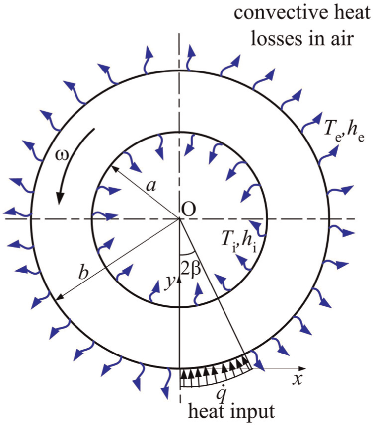
Heat transfer in a roll.
As the roll size is large in cold rolling, it can be considered as an infinite slab. Then, the governing heat conduction equation in steady state is
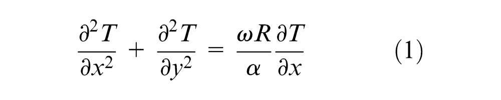
where

For large Peclet number, the heat conduction only in the y (or radial) direction is relevant. 10 Thus, equation (1) becomes

with initial condition

and boundary condition
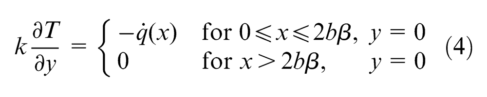
Considering nondimensional coordinates

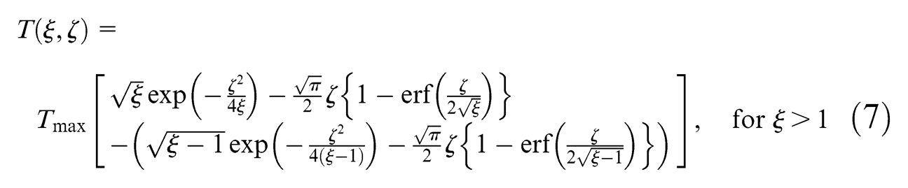
the temperature distribution for zero initial temperature in the roll is obtained as10,35
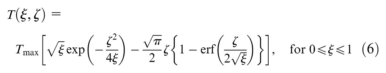
where Tmax is given as
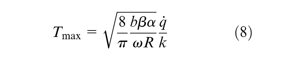
and
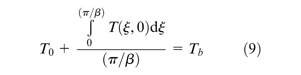
where Tb is the average outer surface temperature of the surface which is obtained as described in the following paragraph. Similar equations can be written for other radial distances.
At steady state, the heat balance provides
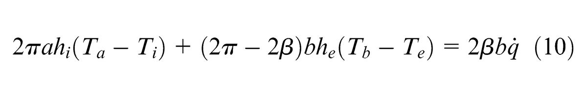
where
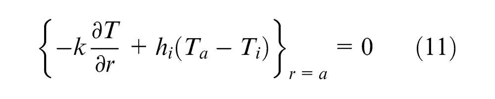
Appendix 2 provides the expression for temperature gradient that is substituted in equation (11) to get
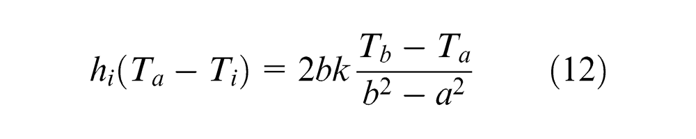
Now solving equations (10) and (11), the average temperatures Ta and Tb along the roll periphery are obtained. It can be assumed that average temperatures are the linear function of radial distance, and thus, knowing the outer and inner average temperatures, the average temperature at any radial distance can be obtained. Equation (9) can now provide temperature T0 to be superimposed on the temperature distribution of outer periphery. Similar modifications can be made for the temperature distributions of other radial locations.
Temperature of strip
The model described in this section is same as that used by Yadav et al. 3 Yadav et al. 3 have carried out deformation analysis by an FEM code developed by Dixit and Dixit 36 and thermal analysis based on the work of Kim et al. 37 In this work, further approximations are introduced to reduce the computational time. First, only four iterations of FEM are carried out instead of eight iterations in the work of Yadav et al. 3 This reduced the FEM computational time by 50%. Due to this, the effect on the accuracy of the plastic deformation power was less than 5%, as even an approximate velocity field provides a reasonable estimation of power, thanks to upper bound theorem. The friction power estimation was affected to the extent of 10% in some cases, but overall estimation of the temperature did not differ much from the exact analysis as friction power is only a fraction of plastic deformation power. Second, in the series solution of Kim et al., 37 only a few terms are taken here, such that the order of error is less than 5%. Usually, this required the evaluation of only five terms.
Figure 1 shows the schematic diagram of the rolling process. One-dimensional heat conduction in plane strain rolling process is considered. Only upper half portion of the roll–strip is considered due to the symmetry of the problem. The plastic deformation is assumed to occur in the domain BGHC as shown in Figure 1. It is assumed that 90% of the work in plastic deformation gets converted into heat, and all the frictional work gets converted into heat. It is also assumed that in the bite zone, temperature in the longitudinal direction does not change significantly as observed by Kim et al. 37 as well as in FEM analysis using ABAQUS package to validate this work. The following differential equation is solved for the bite zone
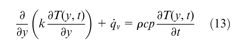
with boundary conditions
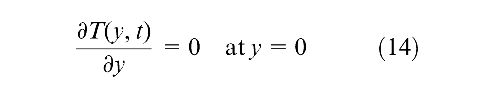
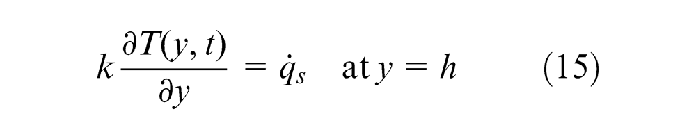
where ρ, cp, k and h are density, specific heat, thermal conductivity and the average semi-thickness of the strip, respectively. The initial condition considered is
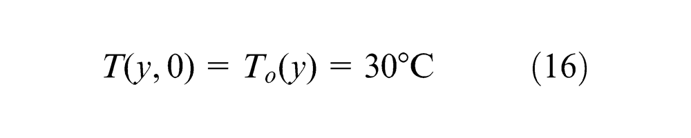
The rate of heat generated per unit of volume
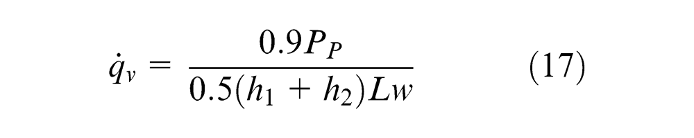

where Pp, Pf, h1, h2, L, w and
One-dimensional equation given by equation (13) is solved by eigenfunction method described by Kim et al. 37 The solution of equation (13) provides the temperature distribution as
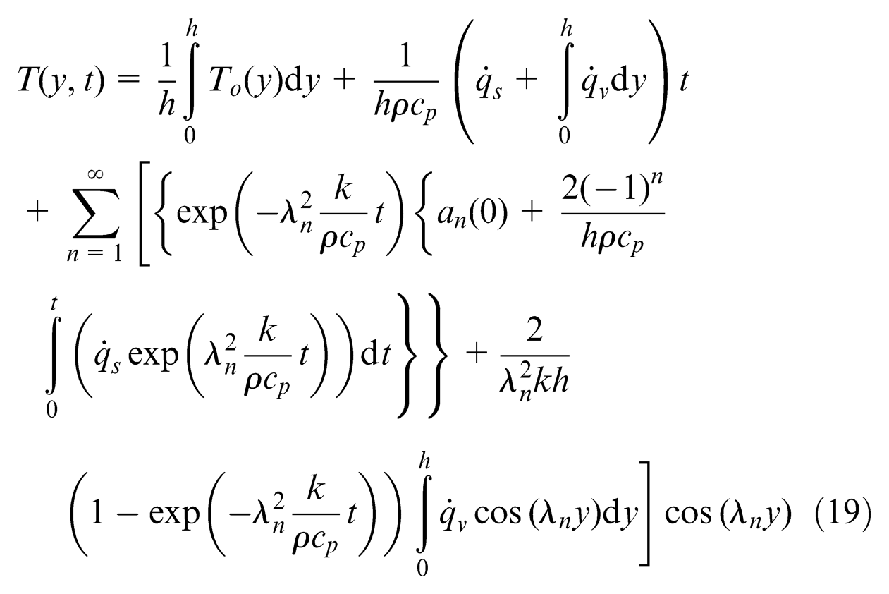
where
Determination of temperature distribution by FEM
FEM is a well-established tool for solving differential equation. It can successfully find out the temperature distribution in rolling. However, it takes more computational time. In this work, for a few cases, temperature distribution was obtained by FEM. For FEM-based estimation, procedure used by Yadav et al. 38 has been used. In this procedure, the temperature distribution in roll and strip is found by finite element software ABAQUS 6.10. The deformation analysis is carried out by the FEM-based code of Dixit and Dixit. 36 The results of deformation analysis are taken after getting the full convergence in velocity distribution of the strip. The procedure adopted by Yadav et al. 38 employs some convergence acceleration method. In spite of it, the procedure takes about 10 min.
Results obtained by FEM-based procedure proposed by Yadav et al. 38 have been taken as the basis for assuring the accuracy of present approximate procedure. Computational times by both the procedures were also recorded. As the main objective of this work is limited to showing an approximate procedure of temperature estimation, only cold rolling examples were taken, in which the increase in temperature is not significant enough to change the material properties. However, in a separate validation study of roll temperature estimation module, even higher temperatures were considered.
Results and discussion
For the validation of the proposed method, the variations of temperature distribution in the roll at different angular velocity and average temperature at the roll–strip interface at different roll radii are studied. The parametric study has been performed at different rolling process parameters such as percentage reductions (%r), exit velocity of strip (V2), coefficients of friction (µ), roll radius (R) and angular velocities of roll (ω).
Validation
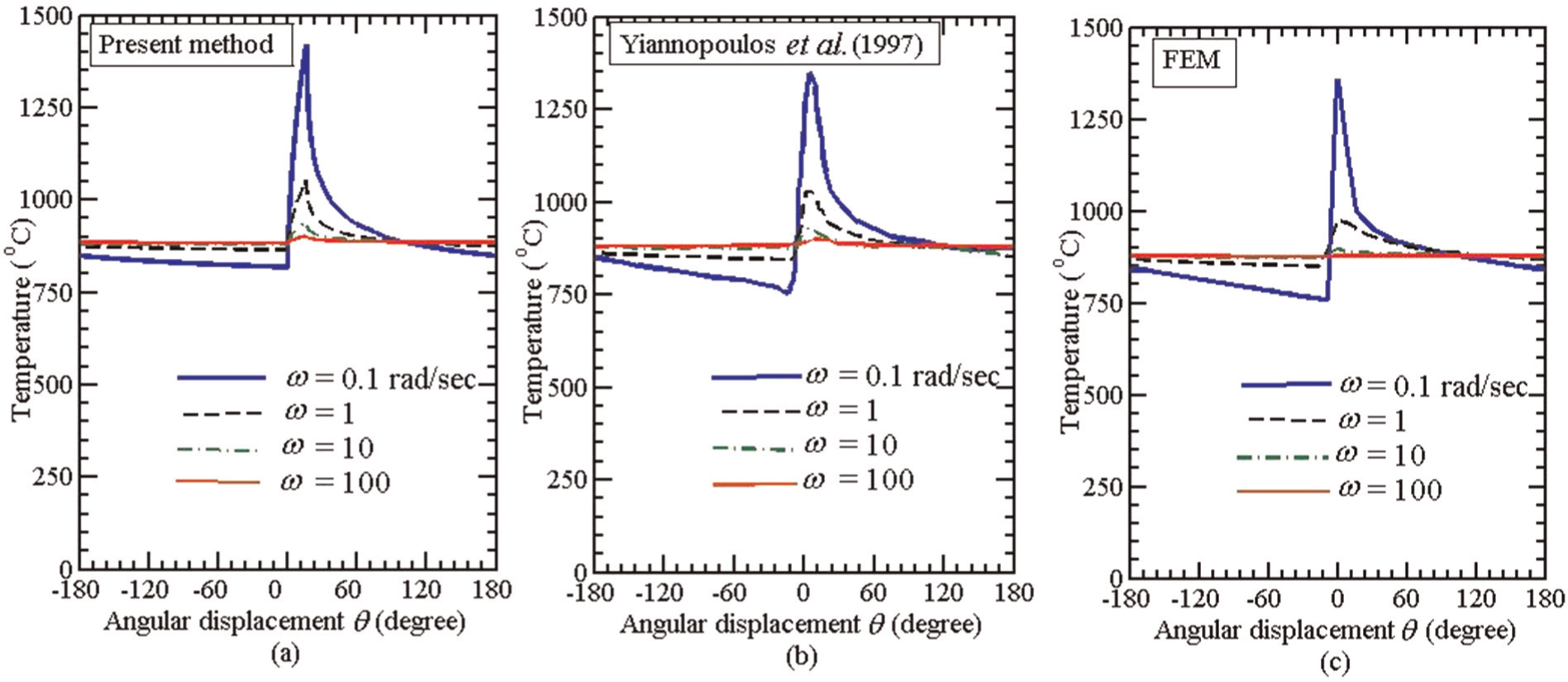
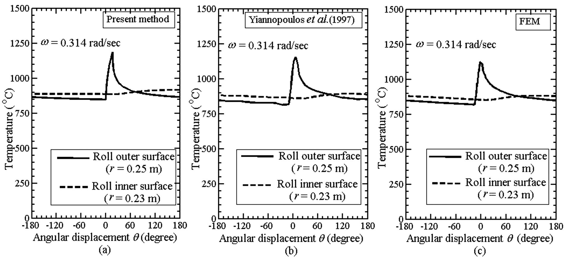
Figure 3 shows the temperature distribution on the surface of the roll at different angular velocities based on the input data of Table 1. These data are the same as taken by Yiannopoulos et al. 39 for analyzing the temperature distribution in roll. Yiannopoulos et al. 39 have not considered the analysis of strip, although it is apparent that the data pertain to hot rolling case. It is observed that the peak temperature of the roll decreases with increasing angular velocity in a steady state. The present result is also compared with the results of Yiannopoulos et al. 39 and FEM 38 by taking only the thermal module. The thermal module of FEM 38 is totally implemented using ABAQUS 6.10. Yiannopoulos et al. 39 have only analyzed the temperature distribution of the roll for prescribed heat and have not considered the strip. Transient temperature distribution in the form of a series expansion is obtained by an integral transform method. Deciding the proper number of terms in a series expansion is very crucial, and Yiannopoulos et al. 39 estimated that their method provided an error of less than 5% in the final results with proper choice of the number of terms. Present method employs the closed-form expression for temperature calculation, which is mathematically simpler compared to the method of Yiannopoulos et al. 39 Figure 3 compares the temperature distribution predicted from the present model with that predicted by the model of Yiannopoulos et al. 39 and FEM. 38 The difference of predicted peak temperatures by three methods is less than 8% at ω = 0.1 rad/s. The difference decreases with increasing ω. The maximum temperature of roll decreases with increasing angular velocity. Figure 4 shows the temperature distributions on the inner and outer surfaces of the roll at the angular velocity of 0.314 rad/s. It is observed that at the outer radius of the roll, the temperature variation on the periphery is more as compared to the inner radius. The agreement between temperature distributions obtained from three models is good.
Material constants for thermal analyses for roll. 39
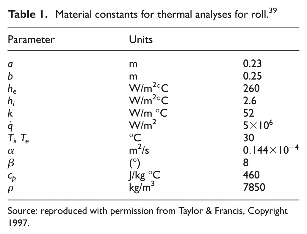
Source: reproduced with permission from Taylor & Francis, Copyright 1997.
Another example is considered in which heat input to the roll is not known. It is required to find out the power due to plastic deformation and friction power by FEM and choose an appropriate partition factor for heat transfer between roll and strip. This was carried out here with the roll and strip properties as shown in Table 2. The ambient temperature is always taken as 30 °C. The roll–strip interface temperature is compared from the experiments of Jeswiet and Rice.
40
The material of the strip is Alloy 1100-H141 of dimensions
Aluminum alloy strip and steel roll properties.
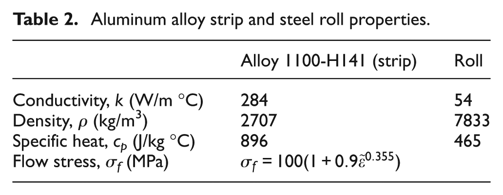
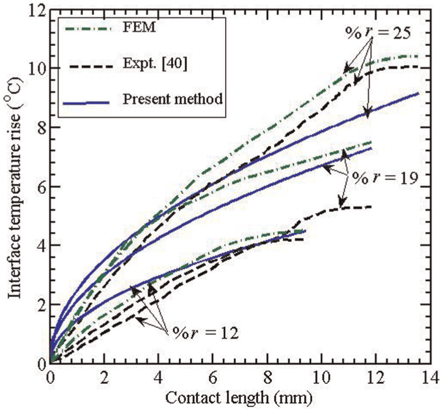
Roll radius and exit speed of strip are 75 mm and 0.096 m/s, respectively. With these data, simulations were carried out for different reductions in strip, and the temperatures of roll and strip are recorded. The value of heat partition factor was decided by matching the average temperature of roll and strip at the roll bite. The quantity of heat distributed between roll and strip was obtained by one-dimensional search. Figure 5 compares the predictions of present model and experimental measurements of interface temperature rise for different percentage of reductions. It is seen from Figure 5 that the present model and FEM predictions are in good agreement with experiments except for the case of 19% reduction. The same observation is also reported in Wilson et al. 16 based on FDM. Wilson et al. 16 suspect that the deviation for 19% reduction may be due to experimental results. They have not provided the details about the deformation modeling but nevertheless have developed a FORTRAN 77 code THERMAL for estimation. The exact detail of computational time has not been provided by them, and the information could have been any way only indicative due to large difference in computer hardware in 1989 and at present in 2013. The present method carries out the deformation analysis by FEM, but due to a number of convergence acceleration techniques adopted, it takes less than 60 s in 2.6-GHz processor and 3.25-GB random-access memory (RAM) AMD Phenom II personal computer (PC).
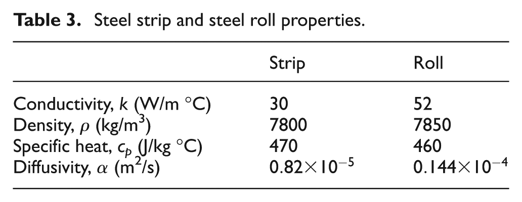
In order to further assess the accuracy of the proposed method, new set of numerical experiments were carried out by taking the thermal properties of strip and roll as per Table 3. The thickness of the roll was kept constant at 20 mm. It was assumed that the actual flow stress of strip is governed by the following empirical relation 36
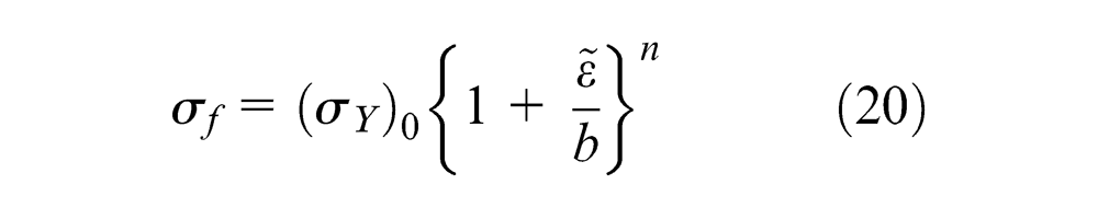
where
Steel strip and steel roll properties.
Comparison of present method with FEM for exit velocity of 1 m/s.
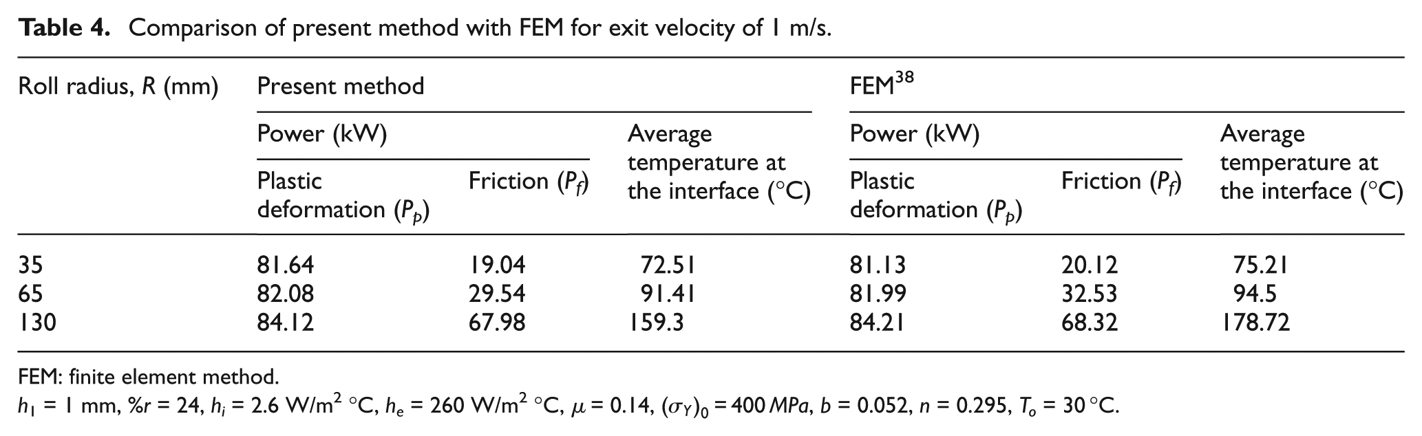
FEM: finite element method.
h
1 = 1 mm, %r = 24, hi = 2.6 W/m2°C, he = 260 W/m2°C, µ = 0.14,
Comparison of present method with FEM for exit velocity of 2 m/s.

FEM: finite element method.
h
1 = 1 mm, %r = 24, hi = 2.6 W/m2°C, he = 260 W/m2°C, µ = 0.14,
One observation is that the difference between present and FEM method is relatively higher for increased roll radius. With the increased roll radius, the contact area and periphery of the roll increase causing enhanced variation of temperature along the periphery. In this work, the steady-state average temperature of the roll is superimposed on the analytical temperature calculated by equations (6) and (7). Also, the interface roll temperature and strip temperature are matched based on the average temperature, and point by point matching is not carried out. These approximations are valid for the small roll radius cases, where the periphery and contact length are smaller. Validity starts becoming weaker as the roll radius increases. Nevertheless, for practical rolling conditions, in spite of the approximations employed, one can expect reasonable results with this method.
Parametric study
The parametric study has been carried out to obtain the average temperature at the roll–strip interface with two different roll radii for different reductions. With increasing reduction, the average temperature increases. Table 6 shows that the effect of roll radius becomes more predominant for higher reductions. This is due to increasing role played by the friction power.
Variation of average temperature at the interface with roll radii for different reductions.
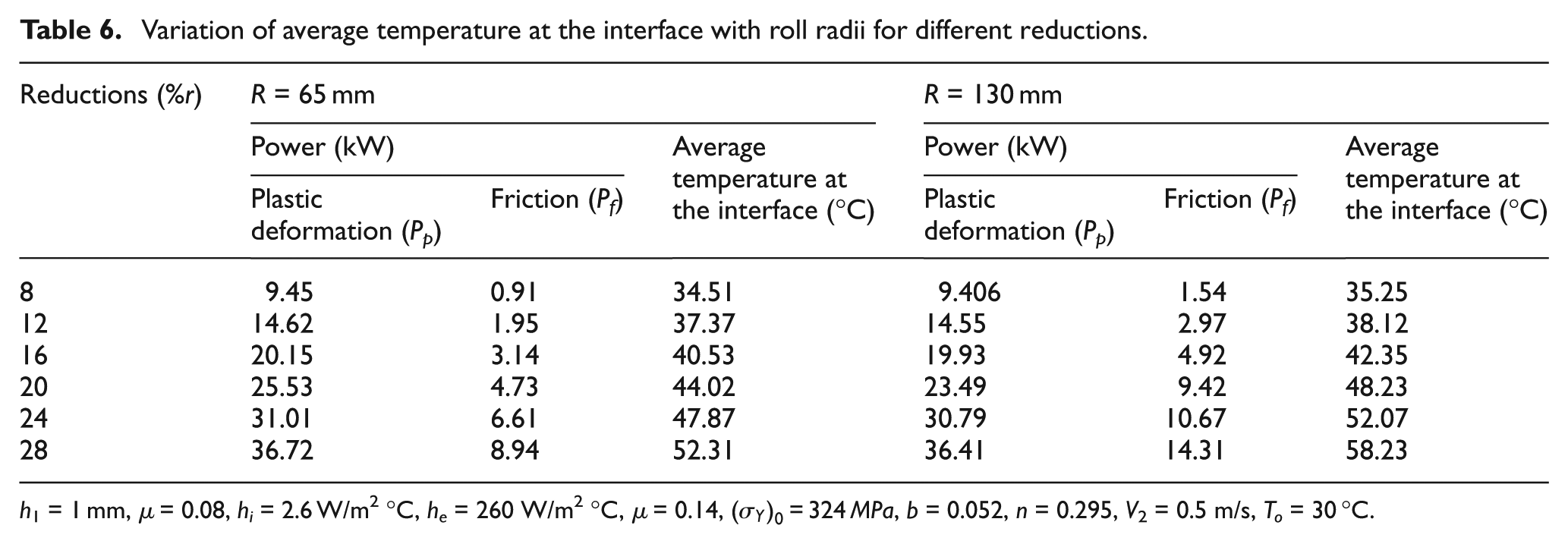
h
1 = 1 mm, µ = 0.08, hi = 2.6 W/m2°C, he = 260 W/m2°C, µ = 0.14,
Table 7 shows the plastic power, friction power and temperature at the interface for two different sets of yield stresses and material hardening parameters. The yield stress in the second set is 10% higher than that in the first set. Similarly, the hardening parameters in the second set are 20% higher than those in the first set. As expected, the increase in flow stresses increases the temperature, and this effect is more pronounced at higher reductions.
Variation of average temperature at the interface with different yield stresses and hardening parameters for different reductions.
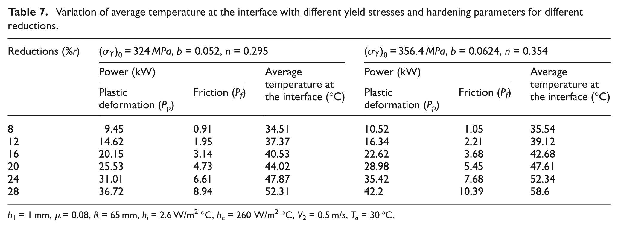
h 1 = 1 mm, µ = 0.08, R = 65 mm, hi = 2.6 W/m2°C, he = 260 W/m2°C, V2 = 0.5 m/s, To = 30 °C.
Figure 6 shows the variation of average temperature at the interface with reduction for different coefficients of friction. It is observed that with increasing coefficients of friction, the temperature at the interface increases. This effect is also more pronounced at higher reduction. Figure 7 shows the variation of average temperature at the interface with angular velocity of roll for two different roll radii. It is observed that the temperature increases with increase in angular velocity, but the rate of increase in temperature with angular velocity decreases with increasing angular velocity. Increase in angular velocity increases the heat generation. It also tends to distribute the heat more evenly on the surface of the roll, making the temperature a weak function of the angular location on the periphery. Initially, the first effect dominates. As the angular speed increases, the influence of the second effect gets dominance. As a result, temperature versus ω plot typically follows the behavior as shown in Figure 7.
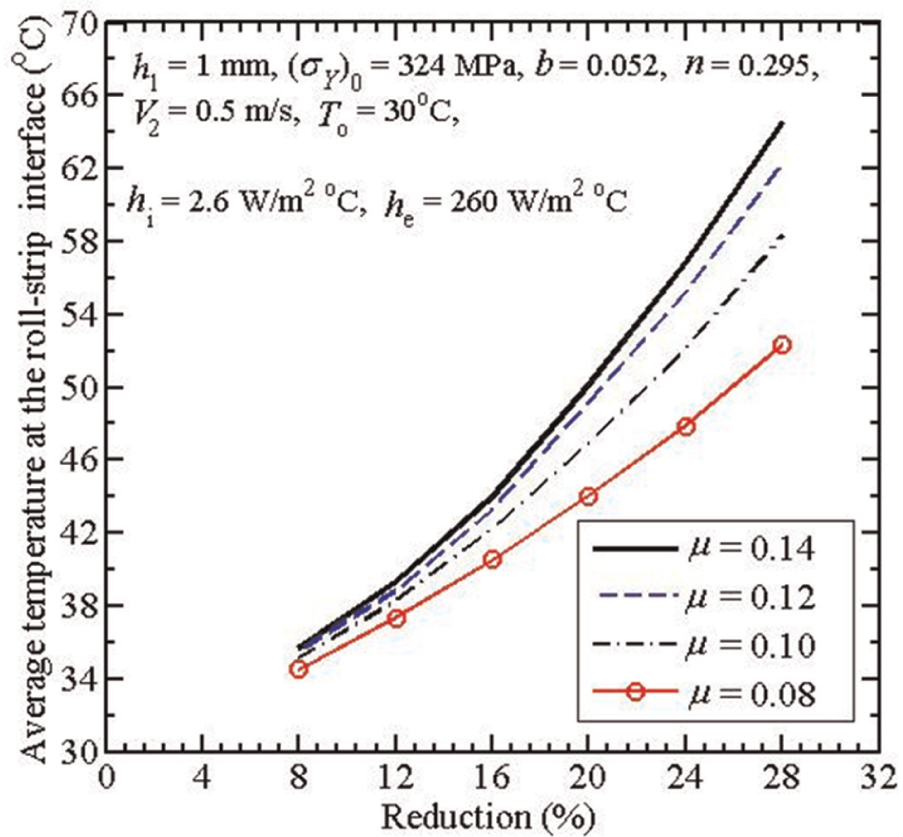
Variation of average temperature at the interface with reduction for different coefficients of friction.
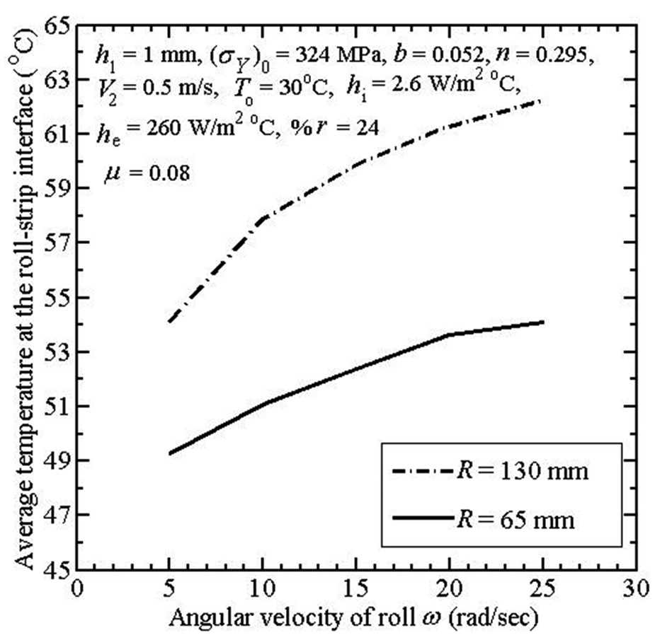
Variation of average temperature at the interface with angular velocity of roll for different roll radii.
Heat partition at the roll/strip interface
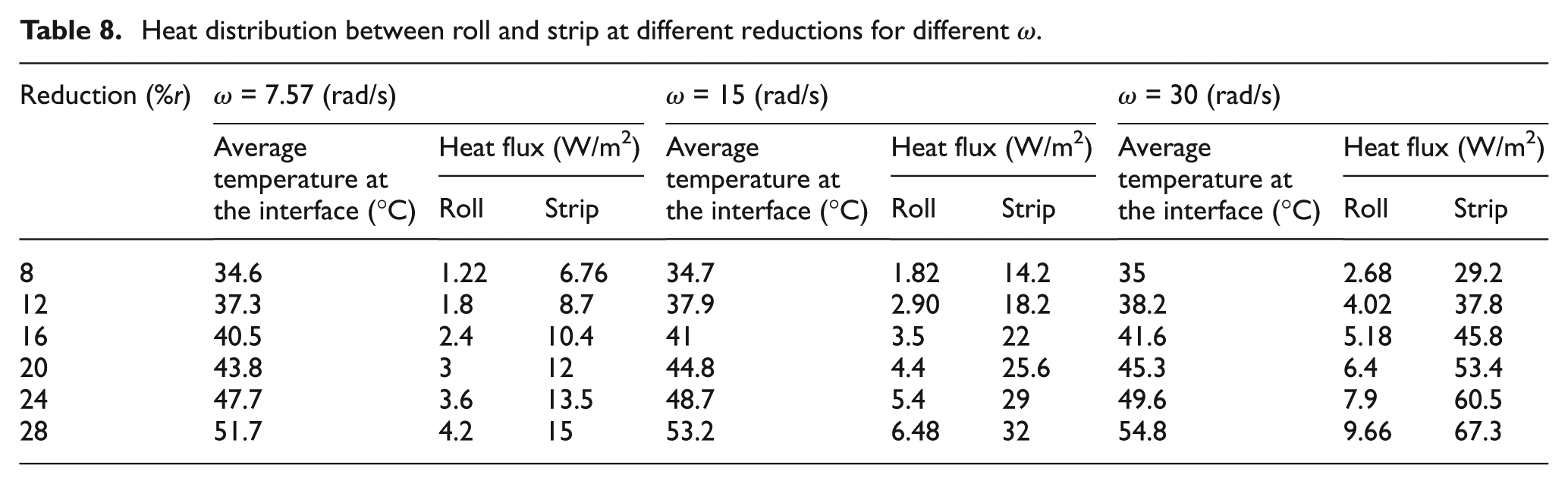
In the cold rolling process, the temperature increases because of heat generation due to plastic deformation and friction. A fraction of this heat goes into roll and the other portion goes into the strip. It is interesting to see the distribution of heat into roll and strip. Table 8 shows the rate of heat input at different reduction for different angular velocities of roll ω. It is observed that the fraction of heat input to the roll decreases with increasing ω. However, the temperature of the roll still increases because the total power increases with ω.
Heat distribution between roll and strip at different reductions for different ω.
Conclusion
In this work, an approximate method is proposed for the estimation of temperature distributions in roll and strip in a rolling process. The method uses simplified mathematical models for heat transfer analysis, which are used in conjunction with a computationally efficient FEM code for deformation analysis. The method is validated with the experimental results available in the literature and a good agreement is found. The qualitative observations are also in line with intuitive understanding. With the increase in roll speed, the variation of temperature at the periphery decreases. Also, the ratio of heat input to roll and heat input to strip decreases with increasing roll speed. This method can be useful for the quick estimate of temperature in rolling process for control or optimization.
Footnotes
Appendix 1
Appendix 2
Acknowledgements
This article is a revised and expanded version of the article titled “An approximate method for computing the temperature distribution in roll and strip during rolling process” presented at AIMTDR 2012, Jadavpur University, Kolkata, India, 14–16 December 2012. The authors thank anonymous reviewers for their valuable suggestions.
Declaration of conflicting interests
The authors declare that there is no conflict of interest.
Funding
This research received no specific grant from any funding agency in the public, commercial or not-for-profit sectors.