
Abstract
Rheoforming is a near net-shape manufacturing technology for fabricating components from light alloys in their semisolid states with improved mechanical properties. In this work, a feasibility study on the fabrication of Silafont 36 aluminum thin plates via rheoforming was conducted. The thin plates were fabricated under different experimental conditions, such as different solid fractions and punch pressures. Electromagnetic stirring was used to prepare a semisolid slurry of Silafont 36 aluminum alloy. Subsequently, the slurry was transferred to die sleeve and injected into the die cavity of the thin plate. The thin plates were successfully fabricated under the optimal conditions of 50% solid fraction and a rheoforming pressure of 130 MPa.
Introduction
Forming in conditions in which solid and liquid coexist is referred to as a semisolid process. 1 The advantages of a semisolid process over a conventional casting process include energy savings, as forming is conducted at relatively lower temperatures, and improved quality through minimization of casting defects, such as internal porosity or shrinkage, because the solidification time is shorter after the injection of feeding material into the die cavity. Furthermore, defects such as air entrapment and misrun would be eliminated in the semisolid processing because the semisolid slurry flows in a non-turbulent manner inside the die cavity.1 –4
There are two main techniques for the semisolid process: thixoforming and rheoforming. Thixoforming starts with reheating of an extruded billet into the semisolid state. Subsequently, the semisolid slurry is formed inside the die cavity. Mass production is limited in the case of thixoforming because the optimal reheating condition is different for each case. The rheoforming process involves preparing the desired semisolid slurry by simultaneous stirring and cooling of the molten metal, which is then injected into the die.5 –9 Through stirring of the molten metal to obtain the semisolid slurry, the structure changes from a dendritic structure (typically found in traditional cast products) to a structure that contains globular primary particles created from the application of shear force. Consequently, when this semisolid slurry is used for manufacturing (rheoforming), components with higher mechanical properties than those manufactured with the traditional casting process will be produced.10,11 For example, Liu et al. 12 reported that in the rheo-die casting process, the strength of fabricated components is improved and hot tear cracks are reduced, as is gas porosity, when compared to high-pressure die casting (HPDC). More importantly, rheo-die casting reduces the solidification shrinkage of material. 12
Methods for preparing semisolid billets include mechanical stirring originating from the studies of Flemings; 13 a slope plate process, initially introduced by Ohno 14 and Keikha et al.; 15 and an electromagnetic stirring (EMS) method in which electromagnetic forces are used to stir the molten metal to overcome the shortcomings of the mechanical stirring method. 16
Despite extensive studies on aluminum alloys, studies on the semisolid process have mainly been conducted for large components of automobile, aircraft, and electronic parts; however, only a few studies have been conducted on thin-plate manufacturing. Furthermore, the fabrication of thin plates with a pattern has been extensively studied by stamping, 17 hydroforming, 18 and hot press forming. 19 Although these metal-forming processes can be used for mass production, the forming limit has been the main issue. More recently, vacuum die casting has been used to fabricate thin aluminum plates with microchannels. 20 However, this process suffers from casting defects such as air entrapment due to the turbulent flow of molten metal within the die. Therefore, investigating the fabrication of thin plates by the semisolid process can significantly contribute to thin cross-section manufacturing technology.
In this study, rheoforming is employed to fabricate thin plates (150 mm × 150 mm × 1.2 mm) with microchannels. In order to analyze formability, properties, product defects, and other features, experiments were performed using slurries with different solid fractions. In addition, the effect of forming pressure on the die-filling behavior and properties of plates was evaluated. Finally, the optimal forming condition is suggested.
Experiment
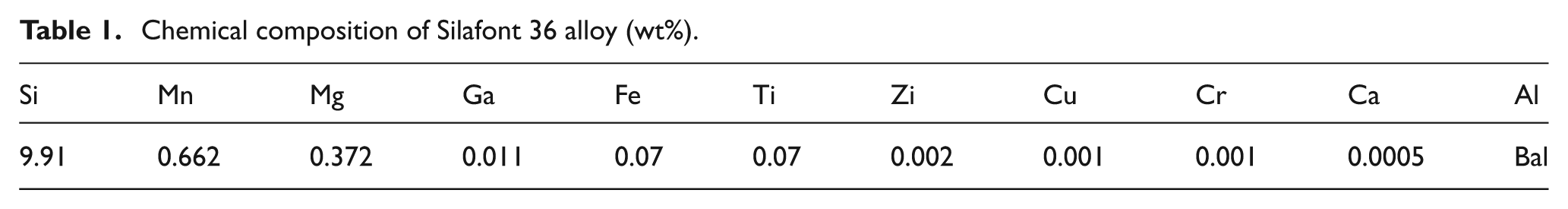
Silafont 36 aluminum alloy was used for the present study. Because this alloy has excellent castability and corrosion resistance,21,22 it is appropriate for the forming and usage conditions of thin plates. The composition of the alloy is presented in Table 1. Mg enhances the ductility of the alloy, and Si at a concentration of 9% improves castability and corrosion resistance. In order to analyze the solid fraction as a function of temperature, differential scanning calorimetry (DSC) was conducted for the Silafont 36 alloy. Analysis showed that solidus and liquidus temperatures for the alloy were 549 °C and 611 °C, respectively. The solid fraction of the alloy versus temperature is shown in Figure 1. In order to evaluate the effect of solid fractions on the forming behavior of the alloy, solid fractions of 20%, 50%, and 80% (corresponding to 575 °C, 579 °C, and 583 °C, respectively) were selected.
Chemical composition of Silafont 36 alloy (wt%).
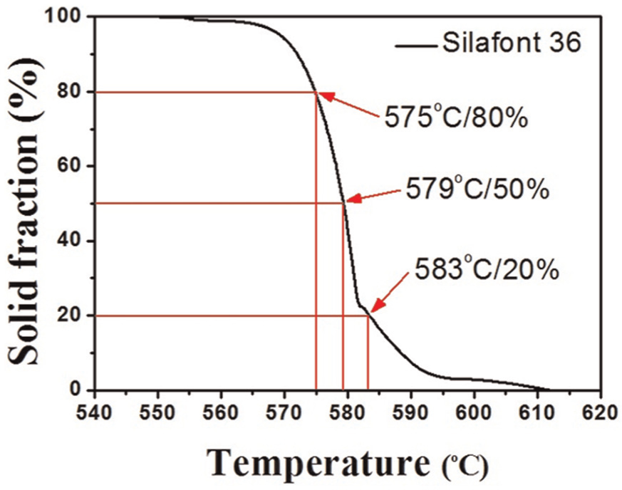
Change in solid fraction with temperature of Silafont 36 alloy.
To remove oxidization products and hydrogen gas from the molten metal, nitrogen gas was injected into the melt for 20 min. The melt temperature was 715 °C before it was poured into the cup to prepare semisolid slurry. In order to prepare semisolid slurry, an EMS system was used. Figure 2 shows the schematic diagram of the EMS system equipment. This EMS system operated with a three-phase current of up to 60 A. The slurry cup was made of a nonmagnetic material. A K-type thermocouple was used to monitor the temperature of the slurry. When EMS was started, the melt temperature was approximately 640 °C. The thermocouple was inserted into the center of the slurry while it was stirring under EMS. Although the stirring current is related to the stirring force, which affects the shape and size of primary particles, overly increasing the stirring current raises the risk of the molten metal overflowing from the cup, owing to the centrifugal force of the liquid metal. Therefore, the test was conducted with a fixed stirring current at 40 A. 23 When the desired temperature was achieved, the thermocouple was removed and the slurry was transferred to the die for rheoforming experiments or quenched into water for the evaluation of semisolid slurry features.
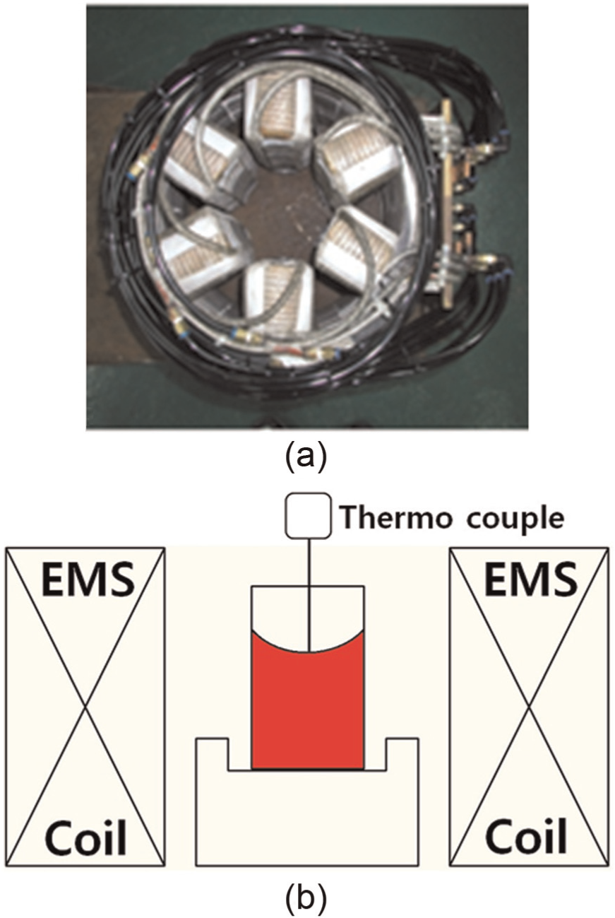
Electromagnetic stirrer: (a) photograph and (b) fabrication of slurry.
The configuration for plate fabrication is shown in Figure 3(a). The shape of the mold cavity and the cross section of the channel are also shown in Figure 3(b) and (c), respectively. The cavity is 150 mm wide, 150 mm long, and 1.2 mm thick. Four overflows were designed in the sides of the cavity. Dies were designed according to an indirect rheoforming method 11 and comprised upper and lower dies. A punch was used for rheoforming. The rheoformed thin plate was ejected using ejector-pins that were attached to the lower die. The temperature of the die was kept approximately constant at 250 °C. A 200-ton hydraulic press was used for the rheoforming experiments. Experimental conditions for rheoforming of the thin plate are summarized in Table 2. Rheoforming pressures of 70, 100, 130, and 180 MPa were applied. The speed of the punch was set at 300 mm/s. After rheoforming was conducted, the thin plate was ejected and was immediately quenched in the water at room temperature.
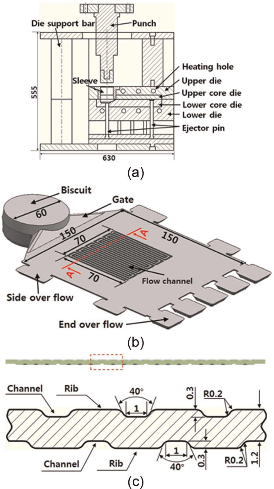
Geometries of die cavity for semisolid forging (in mm): (a) structure of forging die, (b) die cavity, and (c) Section A–A
Experiment of rheology forging.
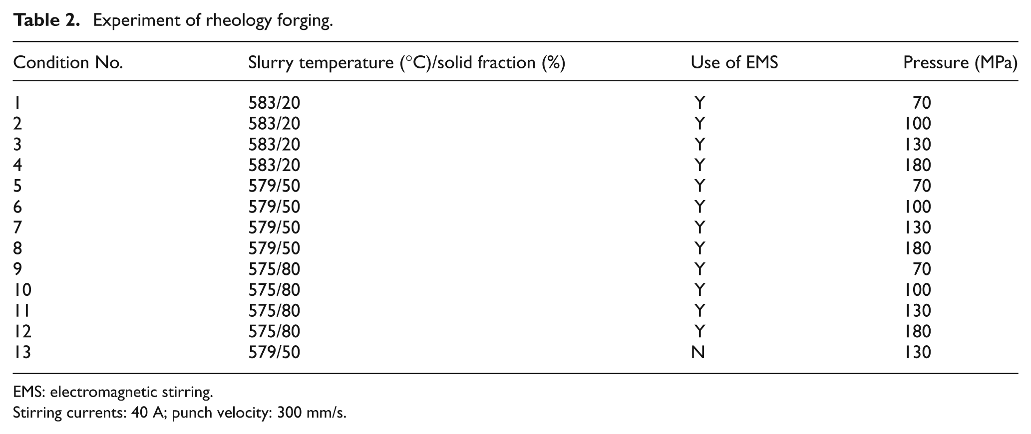
EMS: electromagnetic stirring.
Stirring currents: 40 A; punch velocity: 300 mm/s.
Because the viscosity of the semisolid alloy is much higher than that of molten metal, die wear frequently occurs owing to friction among the semisolid slurry, surface of the die, and sleeve. Moreover, Pinsky et al. 24 have reported that liquid segregation increases as friction between the die and the semisolid slurry increases for Sn–Pb alloy. To prevent these, high-temperature graphite lubricant (Terand) was applied on the surface of the sleeve, punch, and die cavity. An appropriate quantity of lubricant was applied to avoid defects caused by excess lubricant entering the inside of the cavity.
Figure 4 shows the positions of the specimen for analyzing thickness, hardness, and microstructures of the thin plate. For microstructure observation, samples were ground with 2500 grit paper and polished down to 0.25-µm diamond paste. The quantitative measurements were conducted for a minimum of 500 grains by means of iSolution commercial software. Microhardness measurements were conducted using a Vickers pyramid hardness testing machine. The reported values are the average of a minimum of 20 readings.
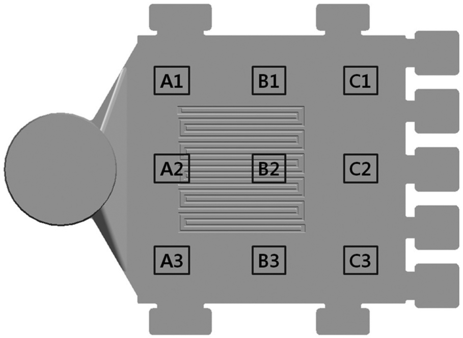
Schematic diagram of specimen position.
Results and discussion
Properties of semisolid slurry
Figure 5 shows the cooling curves for the alloy with and without EMS. Cooling curves were obtained using K-type thermocouples inserted into the center of the slurry just after stirring commenced. The cooling rate of the alloy with EMS was 29.7 °C/min, whereas the rate without EMS was 27.18 °C/min. This means that the cooling rate in the alloys with EMS was faster. In fact, stirring enhanced the heat extraction from the melt because of the rotation of the molten metal. In addition, a rapid decrease in temperature just after the pouring of the molten metal was detected for both alloys with EMS and alloys without EMS (Figure 5).
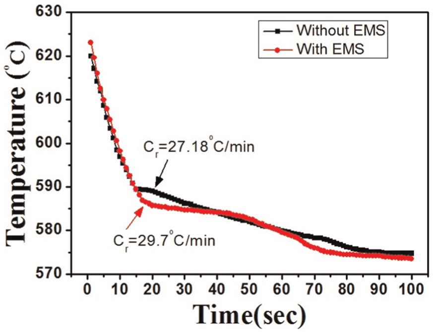
Comparison of cooling rate in Silafont 36 alloy.
Figure 6 shows results of Vickers microhardness measurements for different parts of the semisolid slurry prepared at different temperatures (solid fractions). Note that the semisolid slurries were water-quenched after the desired temperature was achieved. Average microhardness values for the slurries prepared at 575 °C, 579 °C, and 583 °C with EMS were 75.16, 77.05, and 75.13 HV, respectively, whereas for the slurries without EMS, the average microhardness values were 70.73, 68.7, and 71.8 HV, respectively. Clearly, the highest microhardness value of 77.05 HV was obtained for the semisolid slurry prepared at 579 °C with EMS. The overall cross section of the slurry with EMS has an even distribution of microhardness. This can be attributed to the fact that the thermal gradient was removed by stirring. On the contrary, in the case of slurry without EMS, microhardness in the central area is clearly lower than that in the edge and middle. This is due to a higher cooling rate caused by convection and conduction at the edge when the slurry was quenched into water. Overall, the average microhardness was higher for the slurries with EMS than for the slurries without EMS.
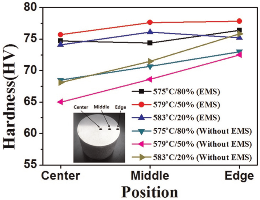
Vickers hardness according to position in Silafont 36 rheology sample.
Microstructural observations of the center and edge parts are shown in Figure 7 for the slurries with and without EMS. For the sample without EMS, the same pouring condition was used and the alloy at a temperature of 575 °C (80% solid fraction) was quenched in water. There were significant differences in the shape and size of primary particles for microstructures of the slurries with and without EMS. Dendritic structures can be clearly observed for microstructures of the slurry without EMS. Dendritic branches in the central area of the slurry without EMS are shorter than those present in the edge area. For microstructures of the slurries with EMS, the primary particles were spheroidized because of the stirring force. During the continuous cooling under the stirring, heterogeneous nucleation occurred at the same time throughout the entire liquid phase. However, all the nuclei formed survived owing to the uniform temperature field created under stirring, resulting in an increased effective nucleation rate, fine particle size, and nondendritic grains.
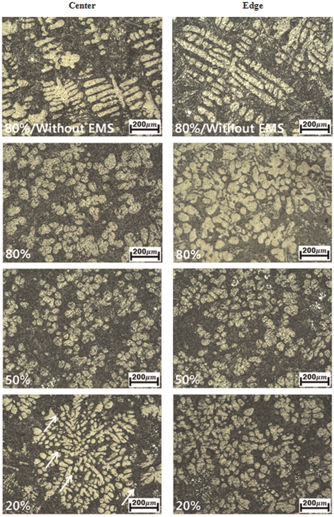
Microstructure of slurry fabricated by different solid fractions (fs) of slurry.
Comparison of the microstructures of the slurries with EMS at different solid fractions shown in Figure 7 reveals that the primary particles in microstructures of slurry at 80% solid fraction are the largest. The quantitative measurements for equivalent diameters of the primary grain are shown in Figure 8. The equivalent diameter of the primary particles increased as the solid fraction increased, regardless of the position. Increasing the solid fractions resulted in large primary particles because particles agglomerated to reduce the interface energy between them as stirring time increased. 25 In addition, primary particles at the edge are larger than those in the central area. The primary particles seemed to become coarser owing to lower temperatures at the edge than at the center. In the central area of the slurry with 20% solid fraction, primary particles were concentrated in one location owing to this low solid fraction. In addition, newly formed primary particles of ∼5 µm were observed (arrows, Figure 7).
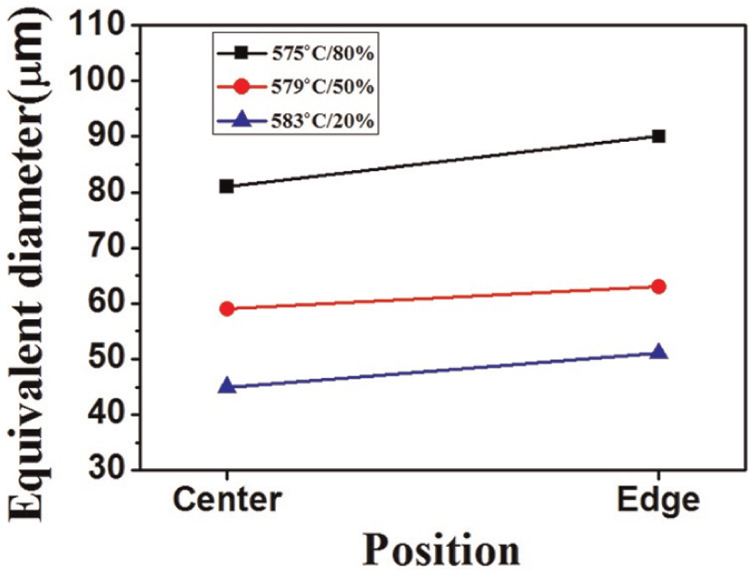
Equivalent diameter by different solid fractions (fs) of slurry.
Fabrication of thin plate
Die-filling behavior
Die-filling behaviors of thin plates according to process parameters (Table 2) such as the solid fraction (temperature) of the slurry and the rheoforming pressure are summarized in Figure 9. X represents incomplete die filling, ▲ represents die filling but with defects on the final products, ■ represents over-charging (flash) of semisolid slurry, and ● represents successful die filling with no visible defects.
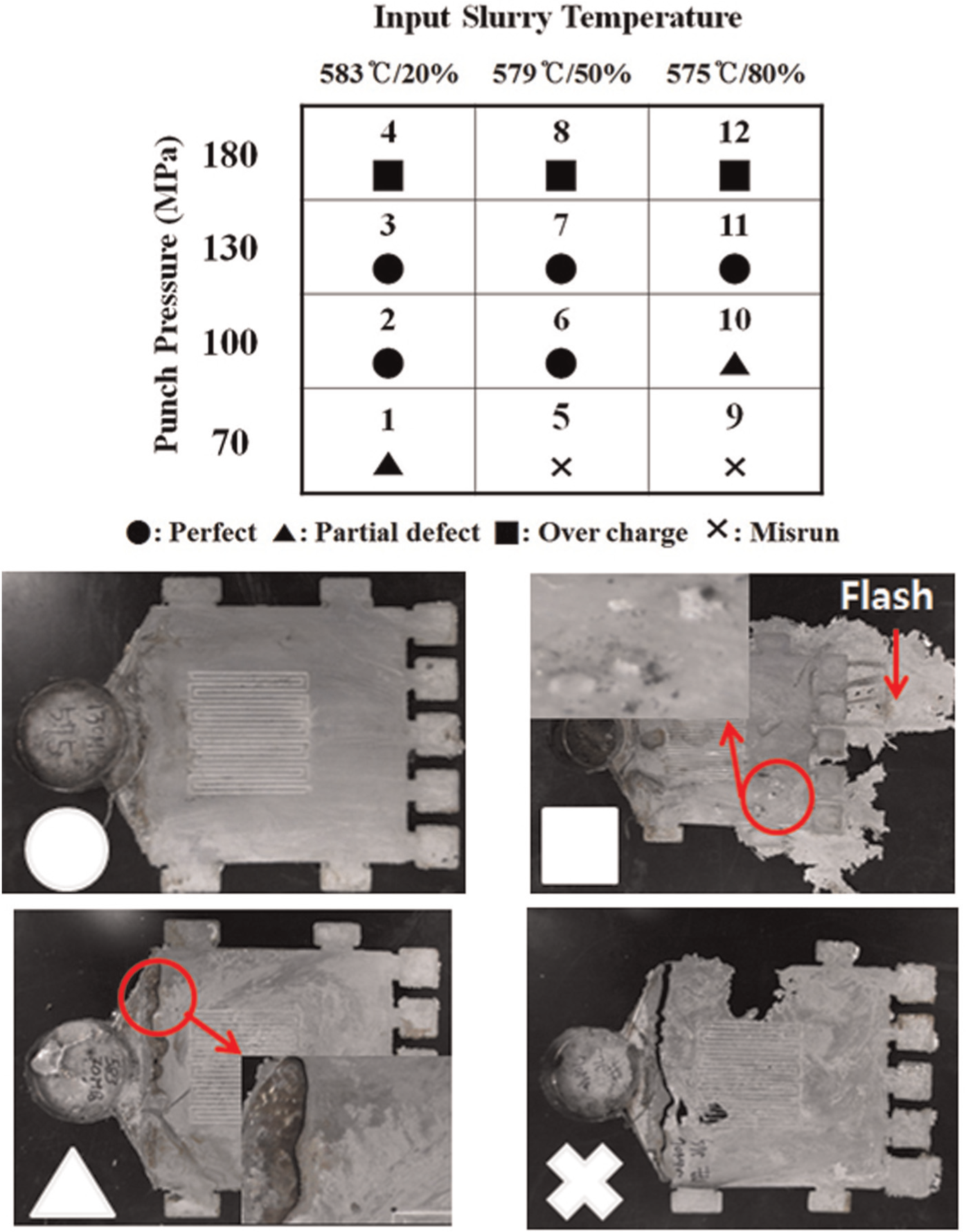
Chart of formability results of semisolid forging experiment.
Perfect die filling occurred under test condition Nos 2, 3, 6, 7, and 11. Generally, die-filling behavior is better at higher rheoforming pressure and lower solid fraction. On the other hand, at a rheoforming pressure of 180 MPa (condition Nos 4, 8, and 12), flash occurred owing to over-charging of the semisolid slurry. For a high solid fraction of 80%, thin plates experienced an incomplete die filling, and defects in the final product were observed.
In the present study, a fan-shaped gate was used in which the width of the gate was increased to allow sequential feeding of the semisolid slurry. It seems that the fan-shaped gate played a key role in increasing the die-filling speed before complete solidification; consequently, it resulted in successful die filling. In other words, although the injection speed (punch speed) of the semisolid slurry was 300 mm/s, the die-filling speed was expected to be three times higher.
In order to explain the critical and detailed effects of processing parameters on the die-filling behavior and the properties of thin plates, a series of results was selected; this is presented in detail in the following sections.
Effect of rheoforming pressure
In order to analyze the effects of rheoforming pressure on die filling (formability) and the properties of the thin plates, the results for thin plates fabricated using semisolid slurry with a 50% solid fraction under the rheoforming pressures of 70, 100, 130, and 180 MPa were selected. These correspond to condition Nos 5–8 in Table 2. Figure 10 compares the actual status of thin plates fabricated at different rheoforming pressures. When the rheoforming pressure was 70 MPa, the die did not completely fill with the slurry. Successful die filling was achieved by increasing the rheoforming pressures to 100 and 130 MPa. However, a further increase to 180 MPa led to lower-quality thin plates; there was a flash at the end overflow (Figure 10(d)) and a lamination defect occurred (Figure 11). The lamination defect occurred because of the high rheoforming pressure, which exceeded the locking pressure of the upper die and resulted in a parting line opening between the upper die and the plate and leakage of semisolid material into this space. In other words, a lamination defect is expected to occur in the second forming when the high pressure applied to the slurry after the first forming causes the upper die to open.
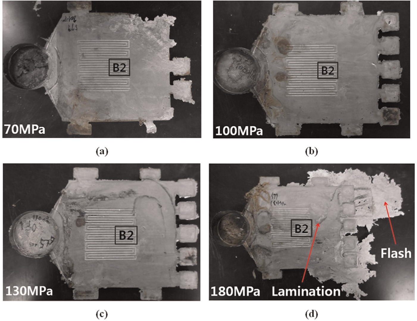
Photograph of thin plates fabricated under different rheoforming pressures using semisolid slurry with 50% solid fraction: condition Nos (a) 5, (b) 6, (c) 7, and (d) 8.
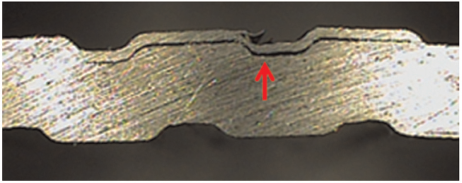
Evidence for lamination defect at rheoforming pressure of 180 MPa and semisolid with 50% solid fraction (condition No. 8).
Figure 12 shows thickness measurements obtained with a digital microscope for the B2 (microchannel) area of samples formed under different rheoforming pressures (using semisolid slurry with a 50% solid fraction). The cut side was polished prior to measurement. If a micrometer is used to measure the thickness, the measurements are not accurate because the surface of the thin plate and the tip of the micrometer might not be perpendicular. Plates fabricated under condition No. 8 (rheoforming pressure of 180 MPa) had a thickness of 1.380 mm, which was much higher than the designed thickness of 1.2 mm. This could be due to the upper die opening during forming at the very high pressure of 180 MPa. Channel depths for condition Nos 5, 6, and 7 (corresponded to 70, 100, and 130 MPa rheoforming pressures, respectively) were measured to be 0.307, 0.292, and 0.307 mm and the thicknesses were 1.207, 1.210, and 1.213 mm, respectively. Slight differences between the die design drawings and the measurement results of the channel depth and thin-plate thickness are probably due to the tolerance in die fabrication.
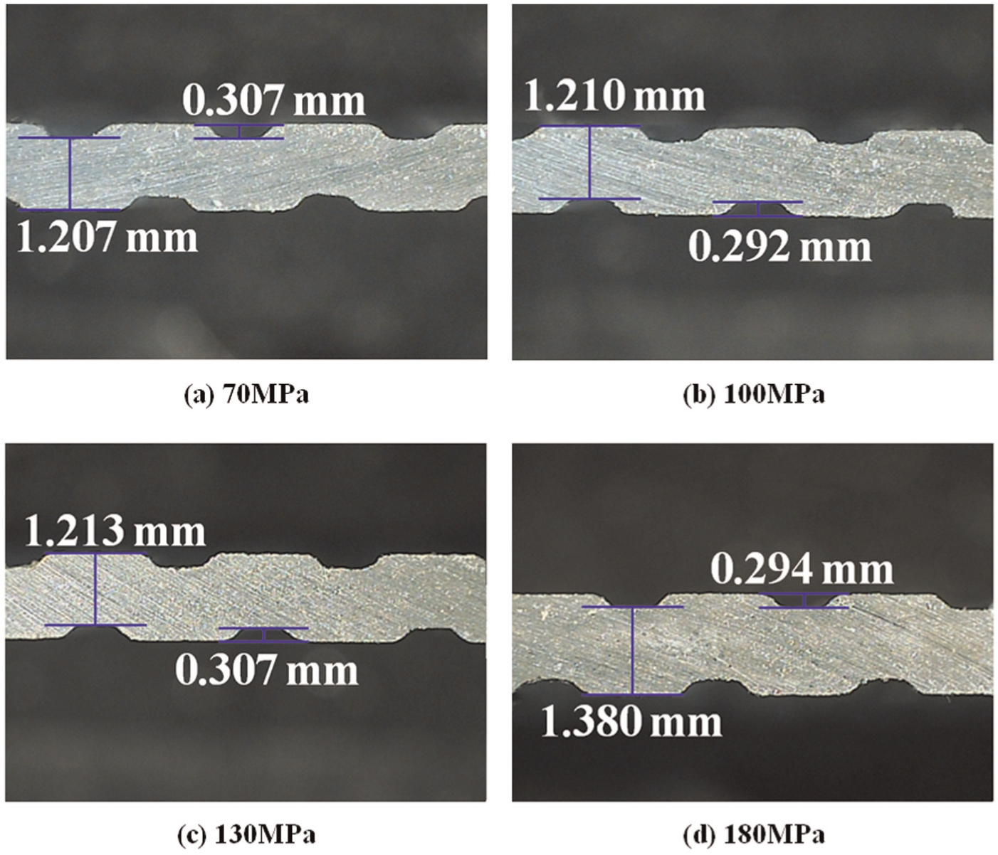
Thickness measurement of channel area for plates rheoformed at different pressures using semisolid slurry with 50% solid fraction: condition Nos (a) 5, (b) 6, (c) 7, and (d) 8.
Typical microstructures of the plates are shown in Figure 13 for rheoforming pressures of 70, 100, 130, and 180 MPa. Most of the primary particles in the microstructure of the samples were spheroidal. The number of primary particles for condition No. 8 (rheoforming pressure of 180 MPa) seems to be lower than that for the other conditions. In addition, the sample under condition No. 8 exhibited a nonhomogeneous distribution. In other words, liquid segregation occurred. Furthermore, the size of globular primary particles decreased upon increasing the rheoforming pressure. Accordingly, it could be suggested that the increased rheoforming pressure broke the globular particles into smaller ones. More importantly, rheoforming with low pressure might increase the porosity of the microstructure. Typical evidence for porosity is shown in Figure 13 for the plate rheoformed at 70 MPa (condition No. 5).
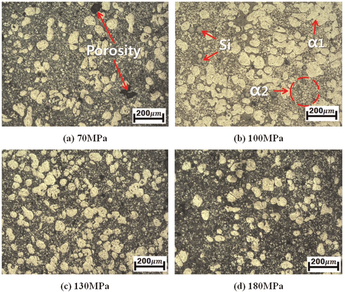
Microstructures of sample fabricated under different pressures: condition Nos (a) 5, (b) 6, (c) 7, and (d) 8. The solid fraction of the semisolid slurry was 50%.
Effect of solid fractions
Figure 14 shows a comparison of die-filling behaviors at different solid fractions of 20%, 50%, and 80% corresponding to condition Nos 2, 6, and 10, respectively, at a constant rheoforming pressure of 100 MPa. At the solid fraction of 20%, 50% perfect die filling occurred. This was due to the high liquid content. However, for the solid fraction of 80%, the gate part and the thin-plate part separated after forming. This is probably due to the lack of feeding, which was because of the fast solidification of semisolid slurry inside the die cavity at the high solid fraction of 80%. As a result, the solidified part of the plate inside the die separated from the material inside the sleeve in the semisolid state while forming occurred in the gate area. In addition, the surface was uneven and rough because of the high solid fraction.
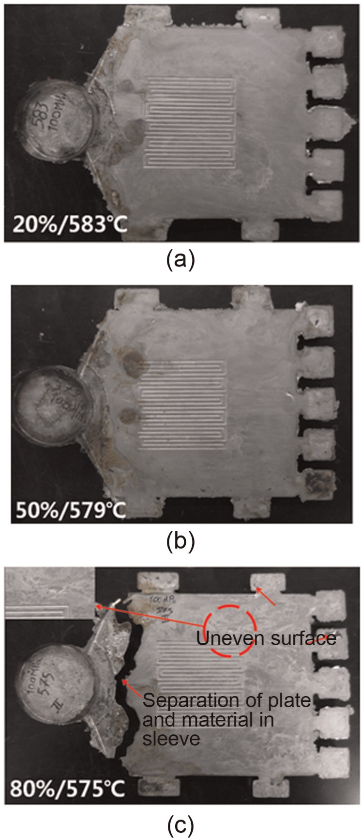
Photographs of sample fabricated by different solid fractions under application of 100 MPa rheoforming pressure.
Figure 15 shows microhardness according to the locations shown in Figure 4 for samples fabricated at different solid fractions. Overall, the location A2 (adjacent to the gate) had a higher microhardness than the other locations; this could be a result of the application of higher punch pressure in the gate area, which resulted in work hardening. The microhardness value of the plate fabricated at the solid fraction of 20% was the highest, with an average value of 91.4 HV, whereas at solid fractions of 50% and 80%, microhardness values were 88.2 and 81.9 HV, respectively.
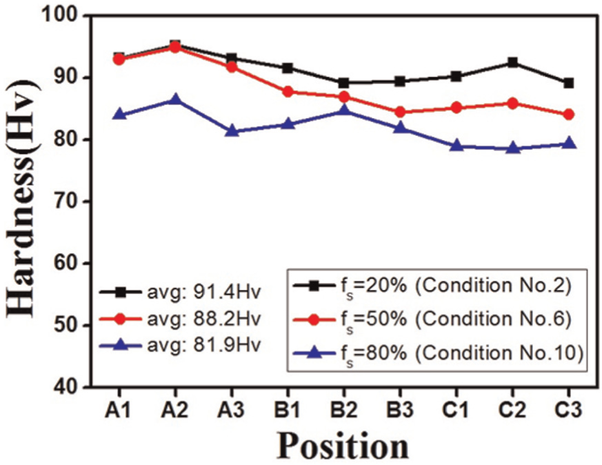
Vickers hardness according to position at different solid fractions (fs). The rheoforming pressure was 100 MPa.
Figure 16 shows the microstructure at the location B2 (microchannels area) of the thin plates at different solid fractions. The microstructure of the thin plate fabricated at the solid fraction of 80% consisted of primary particles α1, whereas at the solid fractions of 20% and 50%, except for primary α1 particles, a distribution of fine α2 particles (1–5 µm in size) was also detected. It is thought that these fine α2 particles were formed after the thin plate was injected inside the die; there was no evidence for α2 particles in the semisolid slurry before rheoforming (Figure 7).
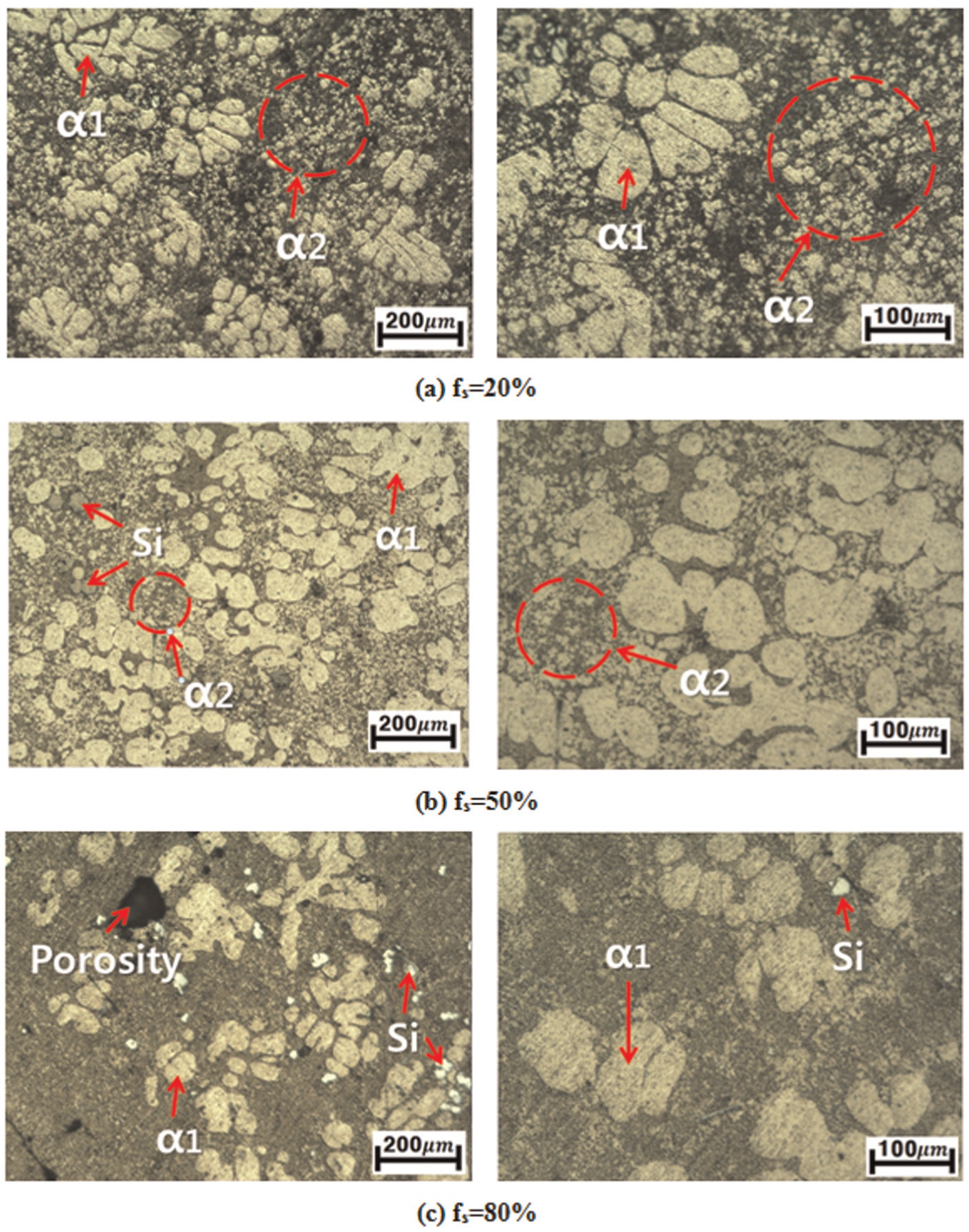
Microstructures of sample fabricated by different solid fractions (fs): condition Nos (a) 2, (b) 6, and (c) 10. The rheoforming pressure was 100 MPa.
Figures 17 and 18 show the surface roughness in the microchannel location (B2) as analyzed by atomic force microscopy (AFM) at different solid fractions. The average surface roughness values for plates at solid fractions of 20%, 50%, and 80% were 274.91, 488.93, and 864.32 nm, respectively. Surface roughness increased as the solid fraction increased (Figure 18).
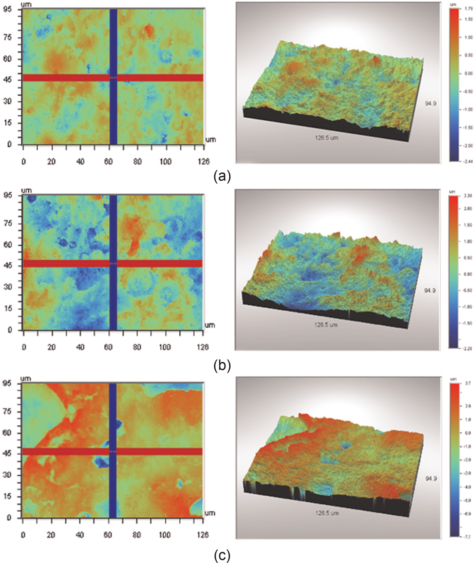
Atomic force microscopy (AFM) image of plate surface in channel fabricated at different solid fractions (fs): condition Nos (a) 2 (fs = 20%), (b) 6 (fs = 50%), and (c) 10 (fs = 80%). The rheoforming pressure was 100 MPa.
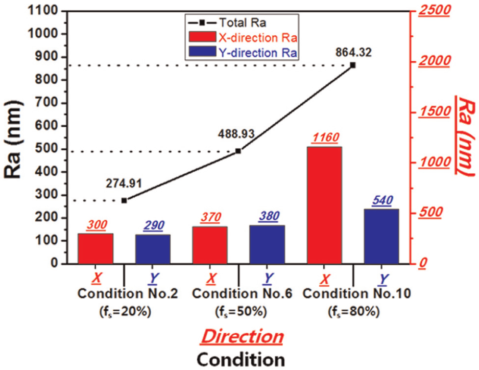
AFM results of average roughness (Ra) according to each direction. The rheoforming pressure was 100 MPa.
Effect of EMS
Under an optimal condition of 50% solid fraction and rheoforming pressure of 130 MPa, plates were fabricated using semisolid slurries with and without EMS. The final results are compared in Figure 19. Complete die filling was achieved for both semisolid slurries with EMS and those without EMS.
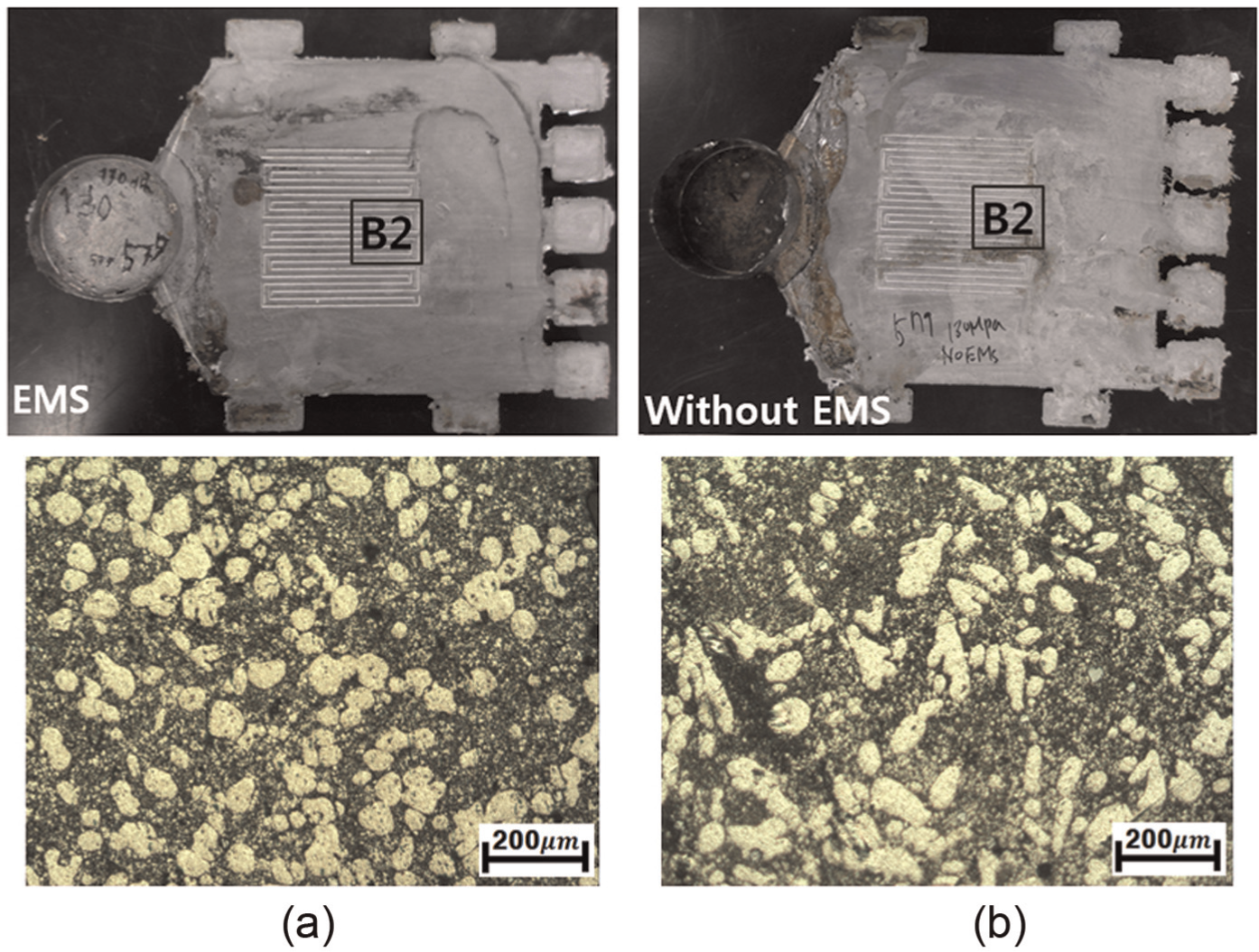
Photographs and microstructures of plates fabricated using slurries (a) with EMS and (b) without EMS. The solid fraction was 50% and the rheoforming pressure was 130 MPa.
Comparison of the microstructures of thin plates rheoformed using the slurry without EMS (Figure 19(b)) with the microstructures shown in Figure 7 for the semisolid slurry without EMS reveals that the dendritic structure of the semisolid slurry (Figure 7) broke into fine particles after rheoforming. As discussed in section “Effect of rheoforming pressure,” α1 primary particles were refined by increasing the rheoforming pressure. However, a globular microstructure with an average diameter of 72 µm was obtained when the plate was fabricated using the semisolid slurry with EMS. Vickers hardness measurements for plates fabricated using the semisolid slurries with and without EMS are shown in Figure 20. The average hardness values were 90.5 and 76.1 HV for the semisolid slurries with and without EMS, respectively.
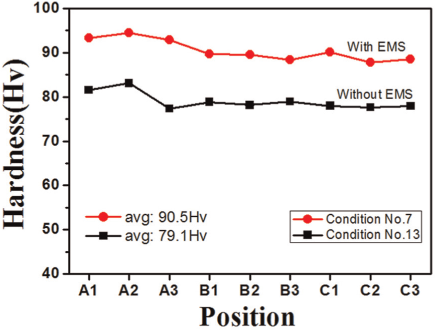
Vickers hardness according to position under different conditions.
Conclusion
A comprehensive experimental study on the feasibility of the manufacture of thin plates through rheoforming was conducted. Semisolid slurries of Silafont 36 aluminum alloys were prepared with 20%, 50%, and 80% solid fractions by EMS. Subsequently, the slurries were injected into the die cavity by application of forming pressures of 70, 100, 130, and 180 MPa. The key conclusions of this study are as follows:
Primary particle size at a solid fraction of 20% with EMS was 45–51 µm. However, particles became larger as the solid fraction increased.
A low rheoforming pressure of 70 MPa was not enough to fill the die cavity, whereas a flash and a lamination defect occurred at a high pressure of 180 MPa. The most appropriate pressure for rheoforming of thin plates was between 100 and 130 MPa.
Rheoforming of thin plates was accomplished perfectly for solid fractions of 20% and 50% with improved properties. However, at very high solid fraction of 80%, rheoforming of the plate was unsuccessful.
The average surface roughness increased as the solid fraction increased, and the average surface roughness was satisfactory (274.91 nm) at the low solid fraction of 20%.
In the case of rheoforming of plates using unstirred semisolid slurry, the usual dendritic structure of cast alloy broke into small particles. However, a nonhomogeneous microstructure was observed.
Footnotes
Declaration of conflicting interests
The authors declare that there is no conflict of interest.
Funding
This research was supported by a National Research Foundation (NRF) of Korea grant funded by the MEST of the Korean Government (No. 2009-0081077) and also supported by a human resources development of a Korea Institute of Energy Technology Evaluation and Planning (KETEP) grant funded by the Ministry of Knowledge Economy of the Korean government (No. 2012-4030200020).