
Abstract
The automotive industry has made increasing use of compacted graphite iron in the manufacture of several components traditionally made of gray iron. However, in some cases, the poor machinability of compacted graphite iron compared to that of gray iron renders production costs uncompetitive. Several researches have focused on the machinability of compacted graphite iron, particularly in turning, milling and drilling operations. However, tapping, which is a more complex operation, has received little attention. The main objective of this work is to investigate the performance of cemented carbide taps when tapping ASTM A450 compacted graphite iron using TiAlN-coated M13 × 1.5 taps with four straight flutes. Cutting tools with different wear levels were analyzed after their use in machining engine cylinder blocks. Tool wear was measured and analyzed using scanning electron microscopy and optical microscopy. The main wear mechanisms observed were adhesion and abrasion.
Introduction
Gray irons are widely used in industry due to their low cost, good machinability and castability, as well as the possibility of improving their mechanical properties by adding alloying elements and/or performing adequate heat treatments. However, in its search for new market opportunities and innovations, the automotive industry has been replacing gray iron with aluminum alloys and compacted graphite iron (CGI) in order to add value to its products. CGI has shown promising potential for use in the automotive industry as their mechanical properties, which are superior to those of gray iron, can help improve engine performance. This is mainly due to the lower power-to-weight ratio of engines manufactured with CGI, which enhances performance, lowering fuel consumption and reduced exhaust emissions.1,2
Due to its higher mechanical strength allied to greater hardness and stiffness, as well as its microstructural characteristics, CGI is also more difficult to machine.3,4 One of the reasons why the machinability of CGI is lower than that of gray iron is due to its lower sulfur that prevents formation of manganese sulfate layer on the tool rake face. This layer of sulfate lubricates the chip–tool interface, improving tool performance and overall service life. 5 The use of CGI in engine manufacturing has motivated several companies and research institutes to improve machining techniques for this specific material. In the case of engine manufacturing, the most critical cutting operations are cylinder honing and boring. 6 Tapping operation is also a key cutting process in engine cylinder block manufacturing, although there are little information available on this process.
The tool material frequently used for machining CGI is the K grade of cemented carbide coated with TiAlN, particularly for drilling process, 6 although polycrystalline cubic boron nitride (PCBN) is a competitive tool material for turning and milling operations. 7 In tapping, the literature is scarce, but practical application in industries indicates the TiAlN-coated cemented carbide as the most used tool material. The main goal of this study is to investigate the wear types, dimensions and mechanisms of TiAlN-coated cemented carbide taps with four flutes used for internal threading of CGI (ASTM A450), using optical microscopy and scanning electron microscopy (SEM).
Experimental technique
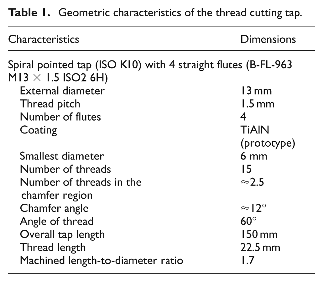
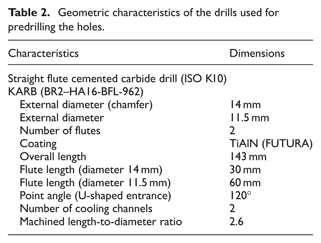
The tapping tools investigated were used for the production of diesel engine cylinder blocks to obtain several wear levels. This study involved tools at their end of life, that is, after machining 12,000 threads (100% of tool life), and at intermediate levels of wear, that is, after machining 2400 threads (20% of tool life), 4800 threads (40% of tool life), 7200 threads (60% of tool life) and 9600 threads (80% of tool life), as well as new tools, thus enabling an analysis of the evolution of wear during the entire life of the tool. Three tools were analyzed for each tool wear condition. All the tapping tools had the same geometry, M13 × 1.5 mm and four flutes, made of K10 cemented carbide coated with TiAlN. Figure 1 illustrates a tap with its teeth and rows. The teeth were numbered from 1 to 15, starting from the chamfered tip of the tool, while the rows were numbered from 1 to 4, starting from a specific mark left on the tool during the grinding operation. The holes were machined with K10 cemented carbide drills prior to the tapping operation. Tables 1 and 2 describe the thread cutting tap and drill geometries, respectively.
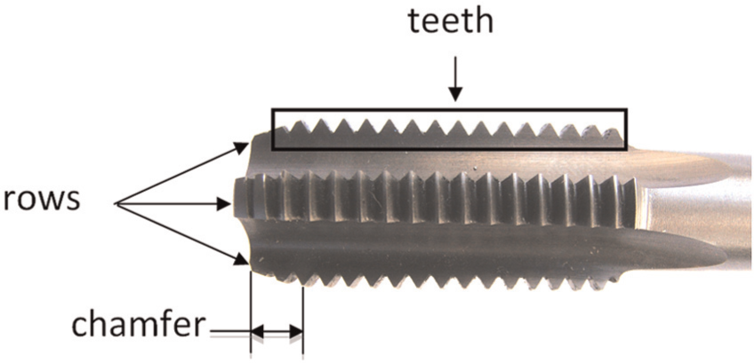
Geometry of a thread cutting tap, showing its teeth and rows.
Geometric characteristics of the thread cutting tap.
Geometric characteristics of the drills used for predrilling the holes.
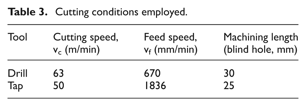
The cutting conditions were kept constant in all the experiments since the aim of this study was to understand the evolution of tool wear of highly complex thread cutting taps and to identify their predominant wear mechanism(s). The cutting conditions used in the hole drilling and tapping operations are given in Table 3. The cutting fluid used in both operations was Hysol 6545, at a concentration of 10% and 12%, applied under high pressure (30 bar) through internal cooling channels.
Cutting conditions employed.
After machining the predefined number of threads, the taps were analyzed by optical microscopy and SEM to measure the wear lands and to identify the main wear mechanisms, using an Olympus BX51M metallurgical microscope with up to 1000× magnification and image digitizing software. The rake face was analyzed at 50× and 100× magnifications, while the flank face was examined at 100, 200, 500 and 1000× magnifications, depending on the level of wear.
In all the tools, only the wear of the teeth in the cylindrical region of the tap was analyzed since they finish the threads, while the wear at the tip of the tap in the chamfered region does not affect the quality of the threads. 8 The flank face of each tooth was measured to quantify the wear levels, as illustrated in Figure 2.
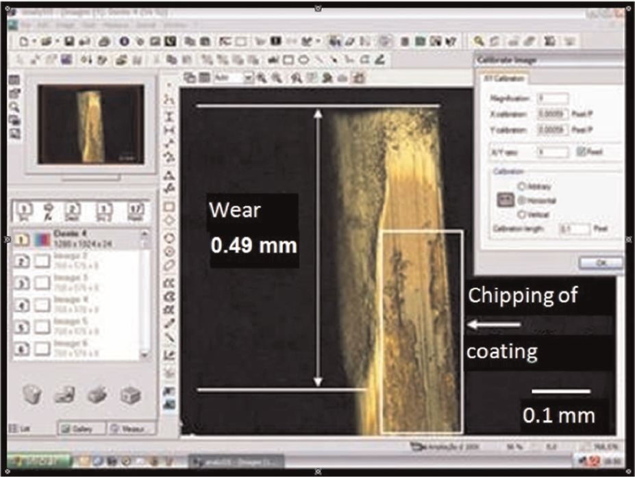
Wear land examined under an Olympus BX51M metallurgical microscope.
After measuring and analyzing the wear levels on all cutting tools using optical microscopy, some of the tapping tools were selected for analysis using SEM (Leica S440i). The tools analyzed by SEM were the ones showing the highest wear levels in each stage of the tool life. This analysis focused on the rows with the highest wear, as well as all the tools showing damage such as chipping or coating detachment. The tools worn regions were also evaluated through analysis using energy dispersive spectroscopy (EDS) to identify the chemical elements present in the cutting edge and possible adhered material.
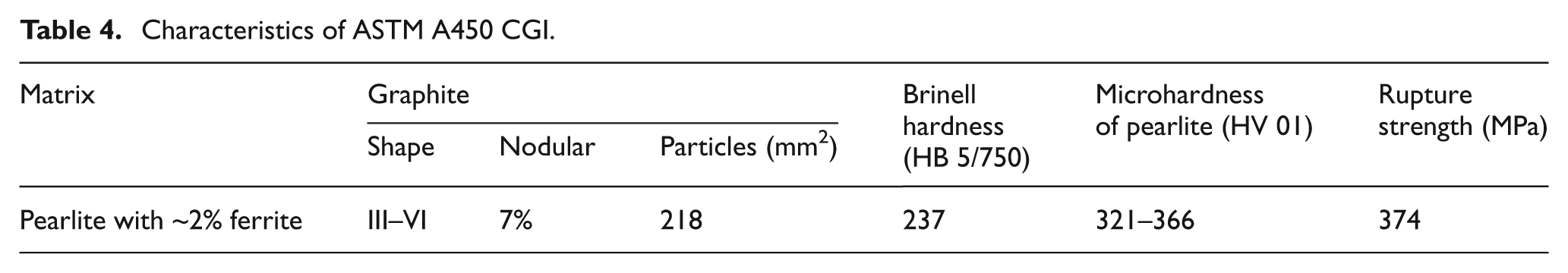
The workpiece material was ASTM A450 CGI, typically used in the fabrication of diesel engines. Table 4 describes the main characteristics of the work material.
Characteristics of ASTM A450 CGI.
The microstructures in Figure 3 are typical of the CGI employed. Note the pearlite matrix containing ferrite and the vermicular and nodular morphology of the graphite.
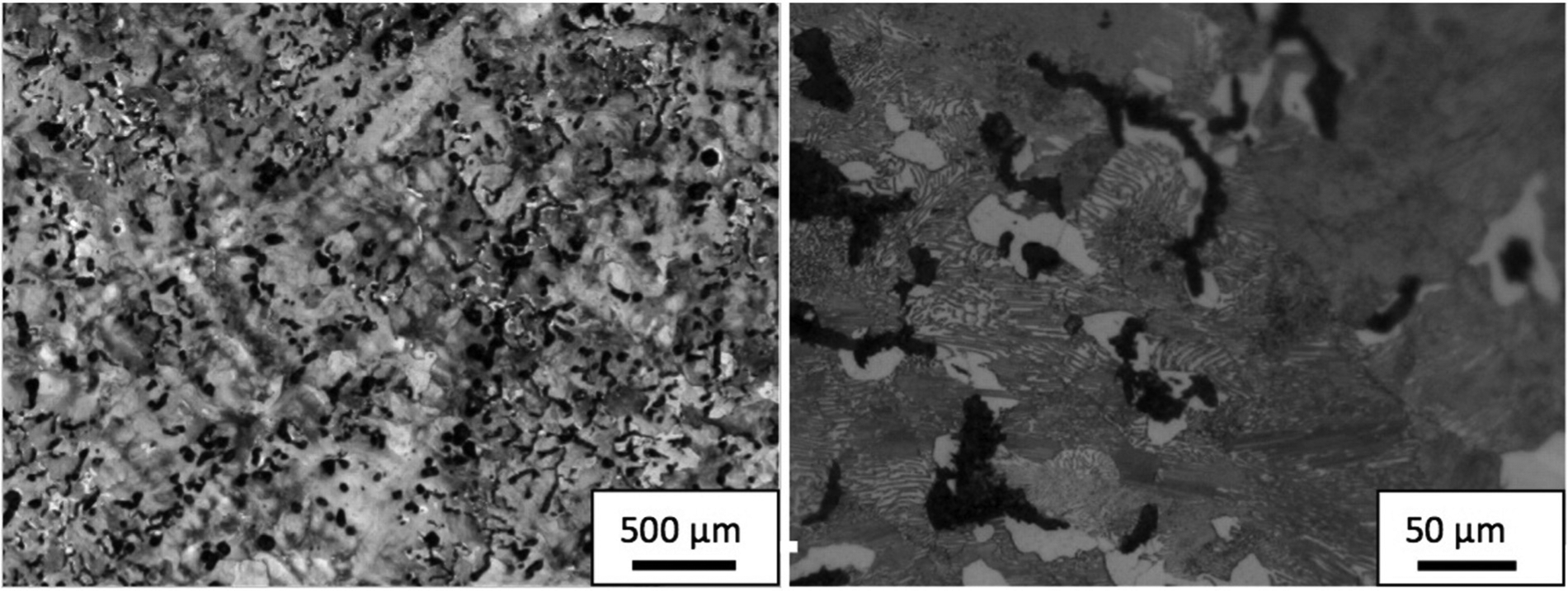
Optical micrographs typical of the core of a sample of CGI A450 used in this work. Etching with 2% nital.
Results and discussion
The main objective of this article is to investigate the failure mode(s) and wear mechanisms of TiAlN-coated cemented carbide tools employed in threading of CGI. Results presented in this article relate only to the most important details of selected tools, rows and teeth examined.
Tool failure mode
The analysis of the worn surfaces of the thread cutting taps indicated the occurrence of wear on both flank and rake surfaces, especially on the first teeth of the taps. As expected, the highest wear was found on the chamfer teeth since the teeth in this region are responsible for chasing the threads.9–11
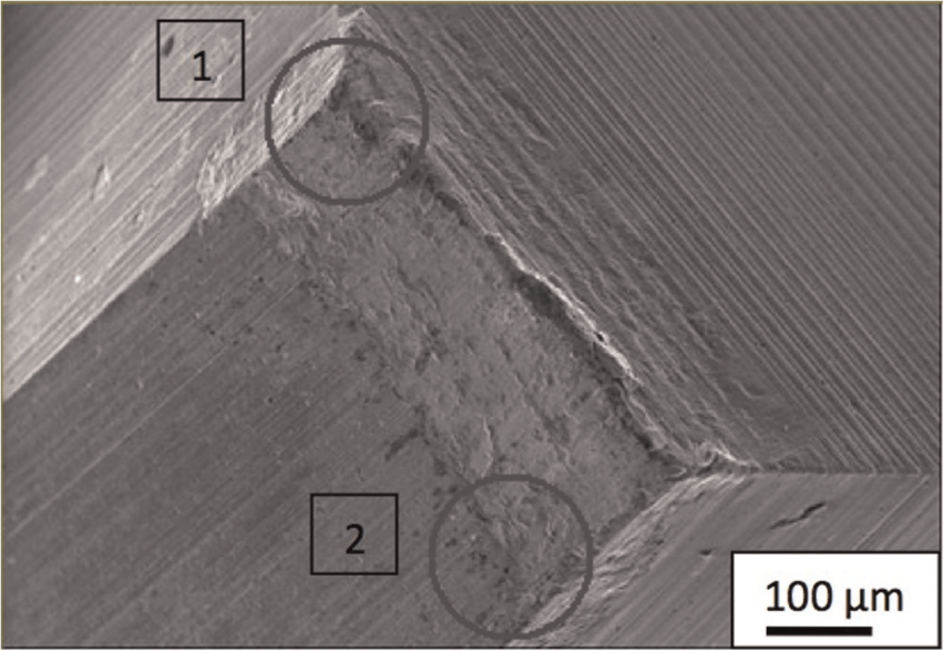
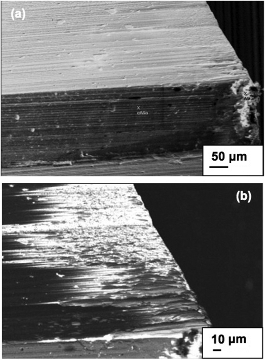
In addition, it was found that wear on both rake and flank faces occurred initially on the teeth in the chamfered region, where it reached almost its highest level soon after commencement of the machining process. Figure 4 shows wear on rake faces in the first threads (chamfered region) of two cutting taps that were used to machine 4800 and 12,000 threads, respectively. All the analyzed threads show a similar type and magnitude of wear.
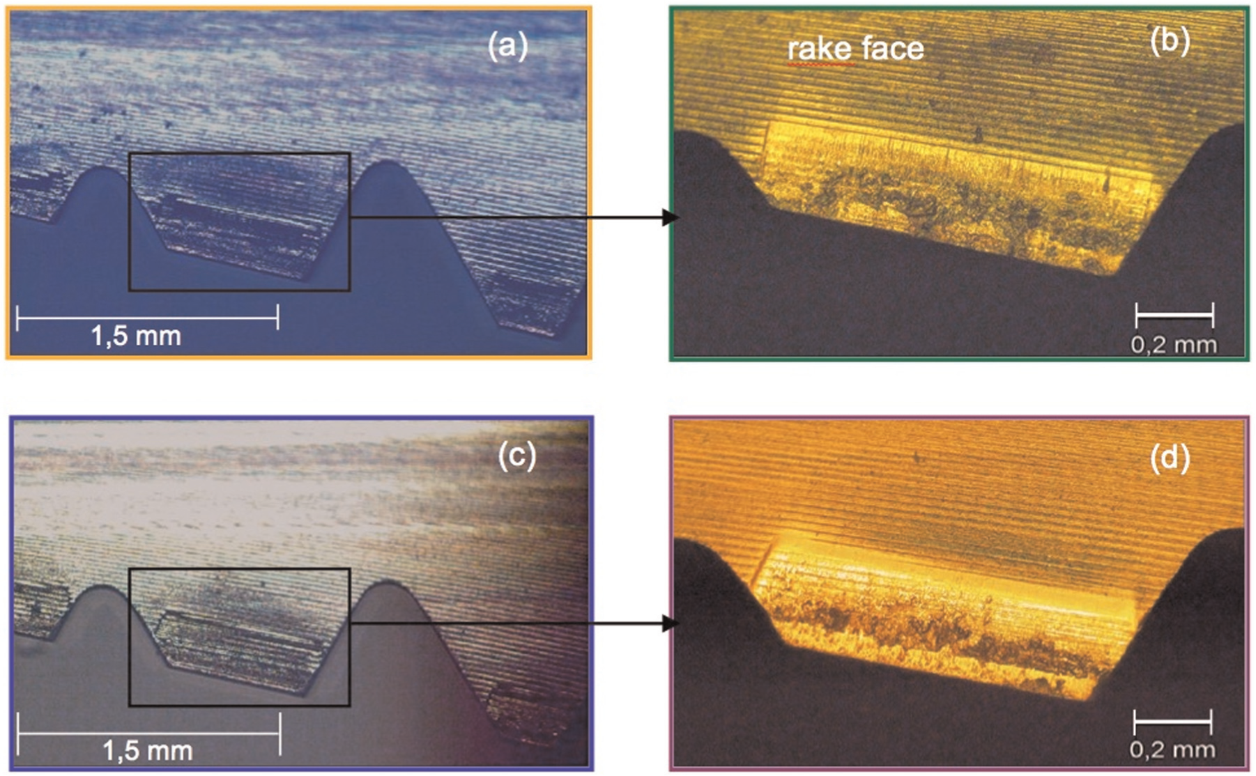
(a and b) Rake face of a tap that machined 40% of the predicted threads and (c and d) rake face of a tap at the end of life (100% of predicted threads were machined).
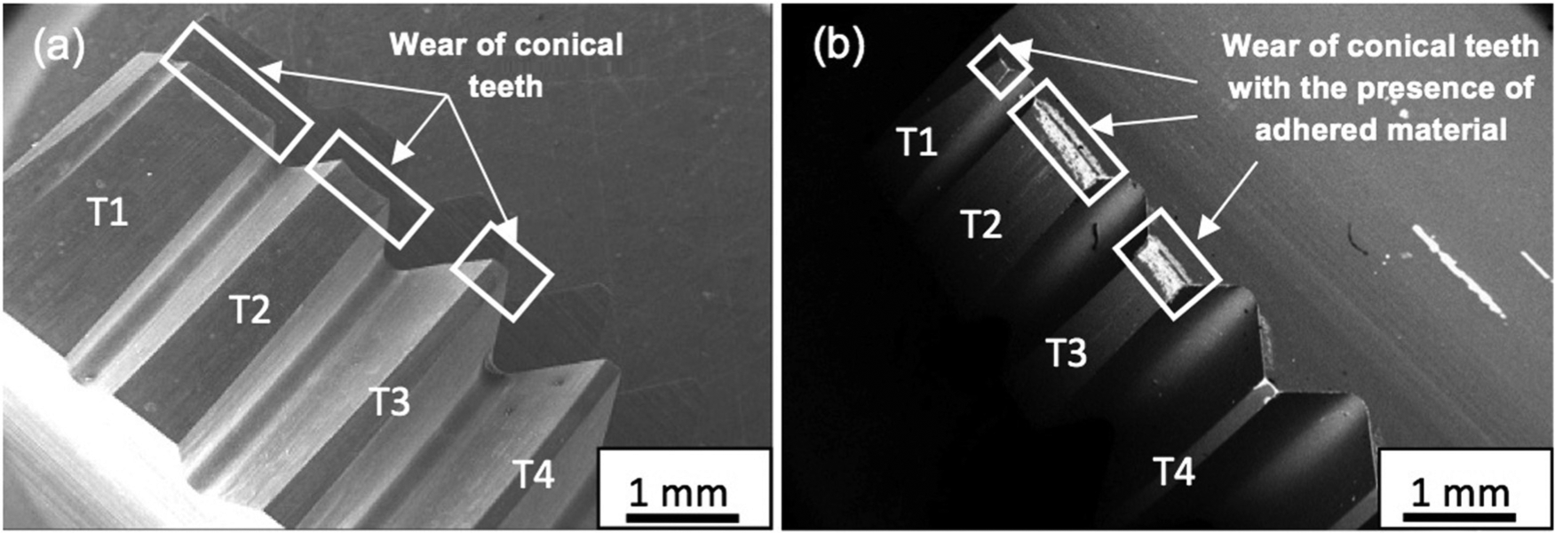
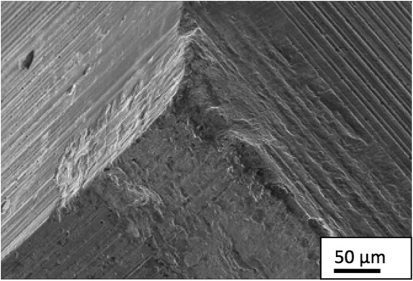
For purposes of illustration, Figure 5 shows a backscatter SEM image of a tool at the end of life. This image reveals the regions affected by wear at the flank and rake faces (in consecutive rows) of the first three teeth (chamfer part) of the tool.
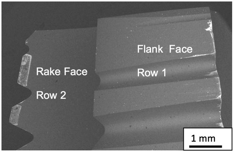
Image of a cutting tap after machining 12,000 threads.
Figure 6 presents images of the flank faces of thread chaser teeth (cylindrical region of the cutting tap) in the second row, where the wear was greatest (teeth T4 to T9 and T12 and T15), in three cutting taps, after machining 2400, 7200 and 12,000 threads. Note that among the thread chaser teeth, the first tooth of the cylindrical part (T4: tooth four) experienced the highest wear. During cutting, the teeth engaged continuously one after the other until they reach a predefined depth. The first teeth (chamfer) began cutting and, as they encounter wear, the thread chaser teeth (cylindrical) contribute to remove material. In theory, the fourth tooth in the first row is the first to inform the final shape of the thread profile, followed by the fourth tooth of the second row and successively until the circle is completed and the next cycle begins with the fifth tooth in the first row. In the return phase, the last teeth, T10–T15, are the first to exit the threaded surface/region in the inverse order, thereby making lesser contact time with the workpiece surface. It should also be noted that the speed of the return movement is variable when using fixed cutting heads, that is, after the cut, the shaft begins to retract the tool, accelerating it until it reaches the preset speed. If acceleration of the machine tool motor is low and the length of the threaded holes is short, the first teeth of the tap will probably be the only ones to make contact with the threads that have already been machined at the programmed speed.
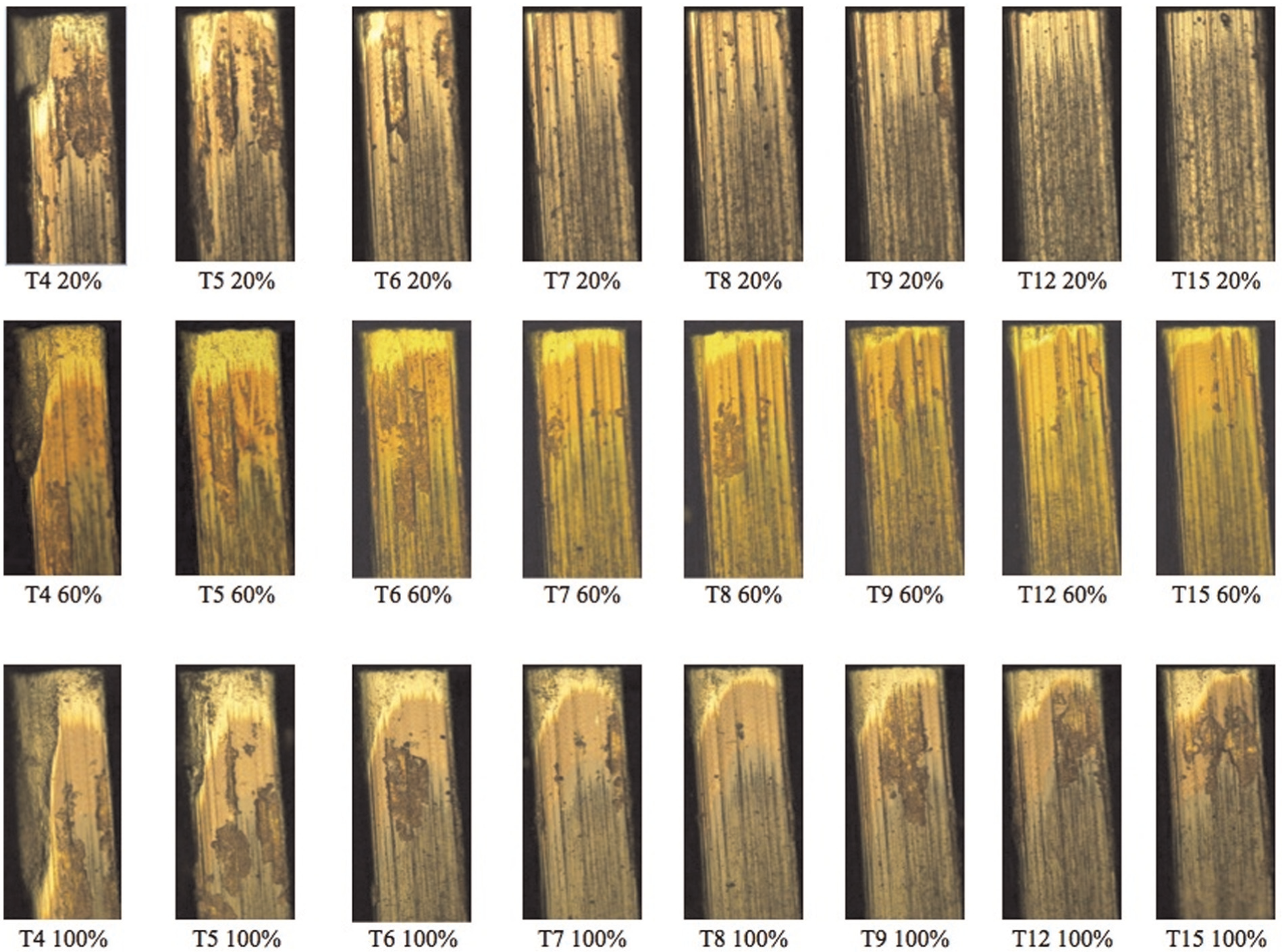
Evolution of wear of the thread chaser teeth in the second row on three tools after machining 2400 threads (20% of tool life), 7200 threads (60% of tool life) and 12,000 threads (100%, end of tool life).
An analysis of Figure 6 also confirms that all the teeth wear increase over time, that is, with the number of machined threads. Moreover, the wear increasingly spread over more teeth in the cylindrical part of the tool, so that after machining 20% of the threads, the wear starting from tooth T7 is practically unrecognizable, while the wear of the tool with 100% use reached the last row of teeth, that is, tooth T15. This finding is illustrated in Figure 7, which plots the highest flank wear values recorded at the flank faces of teeth T4–T15 in tools with several wear levels (20%–100%). It shows the evolution of the wear on each tooth. In the present work, the stipulated number of threads machined of 12,000 was based on the values of flank wear presented by the upper curve in Figure 7 (100% of tool life). However, if one wants to stipulate smaller number of threads for the end of the tool life, instead of the 12,000 threads used here (based on a percentage of this number), the results presented in Figure 7 will enable it. In other words, one can define an end of tool life criterion given by the number of threads machined, based on the wear levels measured on the flank faces of the teeth in the cylindrical region of cutting taps.
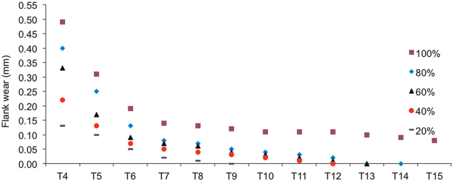
Evolution of flank wear in the thread chaser teeth as a function of the percentage of threads machined by the cutting taps.
Tool wear mechanisms
The various analyses of the surfaces of these tools showed evidence of adhesion of workpiece material on the flank and rake faces, covering large areas of the coating and worn areas. Figure 8(a) shows SEM photomicrograph of the tip of the first row (C1) of a tap after machining 100 threads, using a secondary electron detector. Note the negligible flank wear on both the chamfer and chaser teeth. The magnified images suggest that adhesion occurred, causing coating detachment close to the cutting edge. Figure 8(b) shows SEM photomicrograph of the flank and rake faces of the second row (C2) of the same tap, using a backscattered electron detector. Note the presence of workpiece material adhered to several regions of the tool, mainly on the second (T2) and third (T3) teeth of the chamfer region.
SEM photomicrograph of (a) the first row (C1) of a cutting tap (after machining 100 threads), using a secondary electron detector and (b) the second row (C2) of the same tool, using a backscattered electron detector.
Figure 9 shows the magnified view of the third tooth of the tool shown in Figure 8(a), showing the first wear marks. The CGI adhered to the flank and rake faces of the cutting taps when machining the first threads. On detachment, they pull out particles from the coating and the substrate, typical of attrition wear mechanism,12,13 that is, adhesion followed by pull out of particles from the tool. The chips left visible marks on the rake face, with evidence of the initiation of a crater very close to the cutting edge (approximately 100 µm). Moreover, microchipping occurred in certain regions of the tool, as indicated in the magnified image (Figure 10) of the region identified by “1” in Figure 9.
Details of the third chamfer tooth of the cutting tap after machining 100 threads.
Details of Figure 9 close to the region marked as “1.”
Figure 11 shows a tooth of a tool after machining 9600 threads (80%). The topographic characteristics of the worn region suggest pull out of particles from the surface, typical of attrition wear mechanism. Note, also, the occurrence of microchipping of the cutting edge and coating detachment from the rake and flank faces of the tool.
Wear characteristics of the cutting tap (thread chaser tooth) after machining 9600 threads (80% of tool life).
Coating detachment may have been responsible for accelerating the deterioration of the tool, which caused even greater wear in other regions of the cutting tap. When parts of the coating or the substrate become detached from the tool, they may cause abrasion or even fracture of the cutting tool frequently observed in the breakage of TiN-coated high-speed steel cutting taps used for machining gray cast iron. This breakage was attributed to hard particles pulled out from the coating penetrating the interface between the flank face and the surface of the workpiece during the return movement of the cutting tap, causing the tool to seize up and thus undergo torsional break.
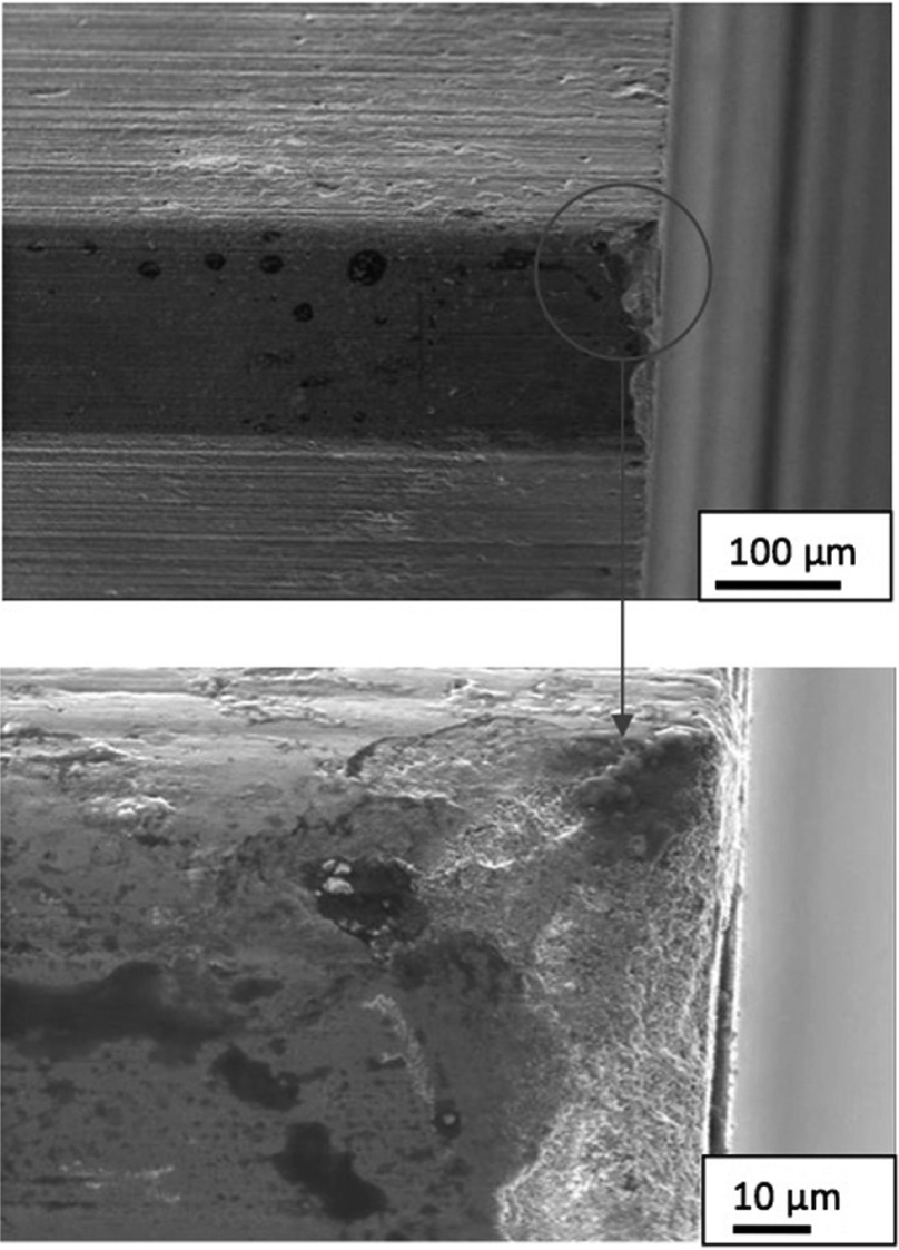
Figure 12 shows SEM photomicrograph of an area of the worn flank face close to the cutting edge of a tool at the end of life (12,000 threads). Figure 13(a)–(c) shows EDS images of points ec23a, b and c highlighted in Figure 12, respectively. The EDS results are used here as a simple qualitative assessment of the elements present in the analyzed region. Figure 13(a) indicates the presence of the chemical elements titanium, cobalt and a large quantity of tungsten (W), the main element in the composition of the tool’s substrate. No chemical element from the tool coating or the workpiece material was detected. This image confirms that coating detachment occurred at this point (in this region), exposing the substrate and thus placing it in direct contact with the workpiece material.
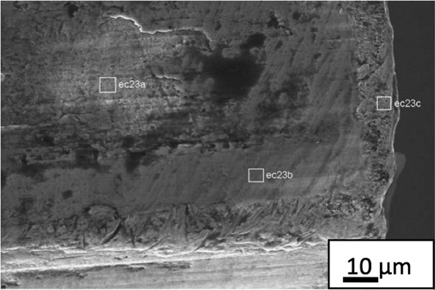
Image of an area close to the cutting edge of the fifth tooth of a cutting tap after machining 12,000 threads.
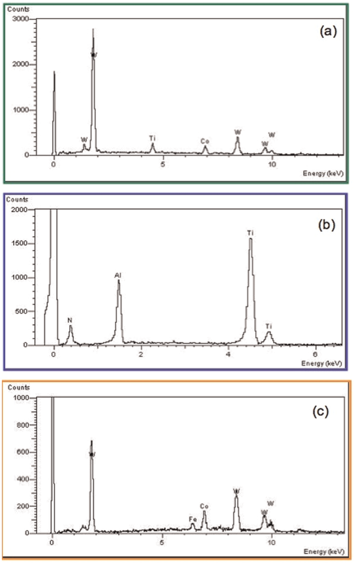
EDS images of points: (a) ec23a, (b) ec23b and (c) ec23c shown in Figure 12.
For a more in-depth analysis of Figures 12 and 13(a), a 6000× magnified image of the same region close to point ec23a was recorded, using electron backscattering (Figure 14) and then repeating the EDS analysis of this point. The coloring of the image reveals the difference between the light (Fe, Ti, Al and N) and heavy (W) metals. The lighter region of this image characterizes the presence of the chemical elements that make up the substrate of the cutting tap.
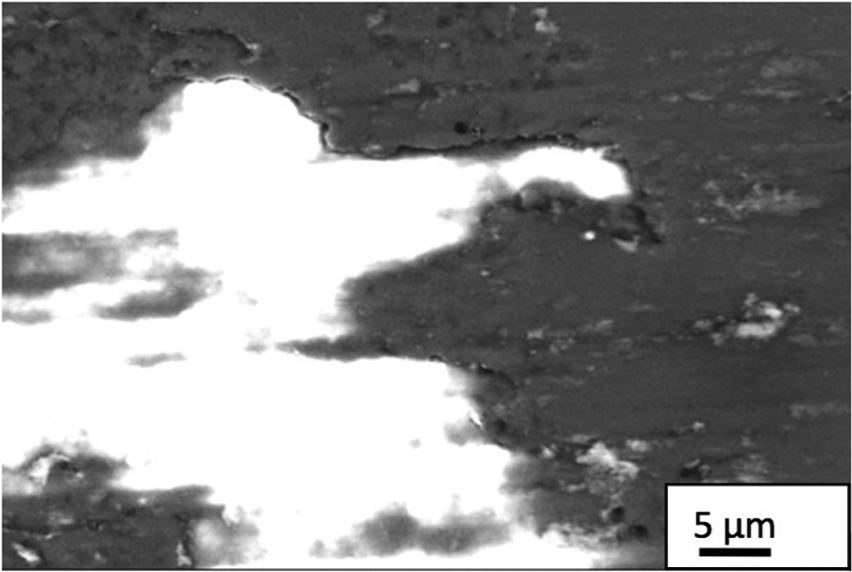
Backscattered SEM image of the region close to the point ec23a in Figure 12, under 6000× magnification.
Figure 13(b) shows the EDS results for point ec23b in Figure 12. This region shows the chemical elements that are part of the composition of the coating, indicating that there was no TiAlN coating detachment or CGI adhesion in this region. Titanium, aluminum and nitrogen are the only chemical elements in the spectrum.
Figure 13(c) depicts the EDS results for point ec23c in Figure 12. The predominant chemical elements in this area are tungsten, cobalt and iron, characterizing adhesion, coating detachment and tool wear. In this case, the presence of tungsten indicates that the substrate at the cutting edge of the tool is uncoated, which favors higher wear. In addition to being harder than the substrate, the titanium- and aluminum-based coating forms oxides (Al2O3) when working at high cutting speeds and thus at elevated temperatures. These oxides can act as a layer that increases lubricity at the interface and also act as a barrier against the conduction of heat into the tool, preserving the latter’s integrity and thus increasing its service life when working at high cutting speeds. 14
Figure 15 shows images obtained by optical microscope, secondary electron SEM and backscattered SEM of the rake face of a tooth in the chamfer region (T2) of a tool after machining 7200 threads (60%). Figure 15(c) shows a magnified backscattered SEM image of the same rake face of the tool, identifying two regions (A and B) that were subjected to EDS analysis for surface characterization.
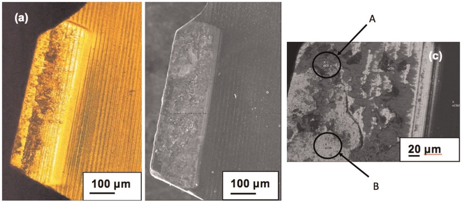
Rake face of tooth T2 of a tool after machining 7200 threads. Images obtained by (a) optical microscopy, (b) secondary electron SEM and (c) backscattered SEM.
Figure 16 shows EDS spectra of regions A and B indicated in Figure 15(c). In region A, note the presence of iron, silicon and carbon, which are elements present in the composition of CGI, characterizing adhesion of the material of the workpiece on this region of the tool’s surface. The spectrum of region B indicates that tungsten is the predominant element, along with traces of titanium, iron and oxygen. This suggests that the coating in this region of the tooth was partially detached since tungsten is the main component of the hard metal substrate. The presence of the chemical element iron in this region is related with adhesion of the workpiece material. Figure 17 shows adhesion of workpiece material on the secondary flank surface of one of the teeth of a cutting tap after machining 9600 threads (80%).
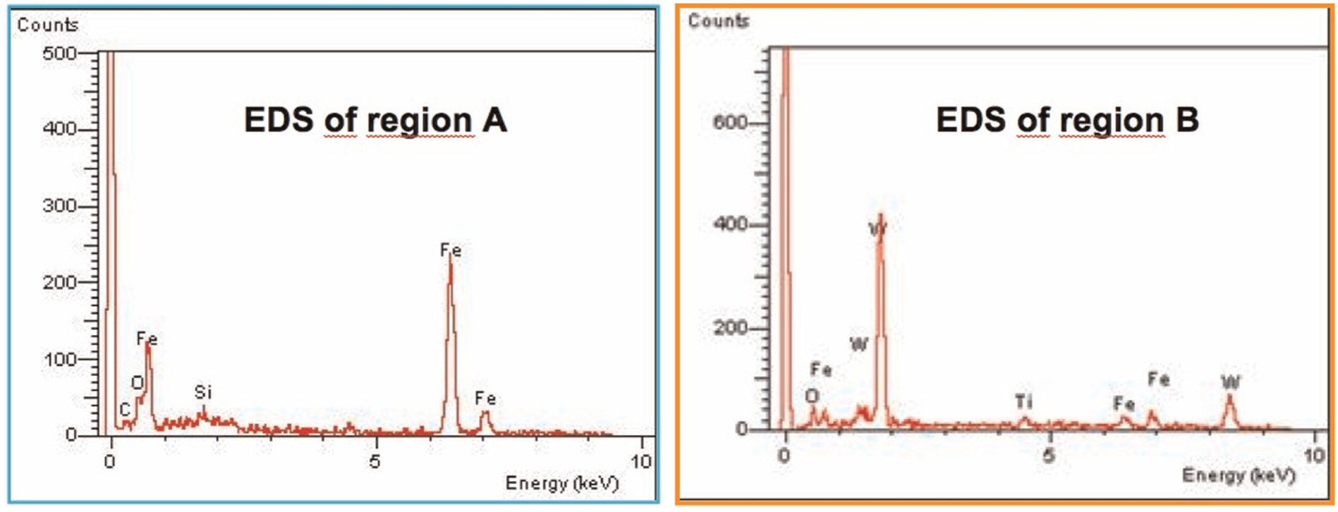
EDS spectra (chemical analysis) of regions A and B.
Adhesion of workpiece material on a tooth of a cutting tool after machining 9600 threads (80% of tool life): (a) details of the SEM image and (b) details of the image quadrant backscattering detector (QBSD).
Adhesion was found to change the topography of the cutting tap. The SEM analyses indicated that adhesion occurred in regions close to the cutting edge, independent of the number of machined threads. However, the size of the worn area was proportional to the number of machined workpieces.
Both flank and rake faces showed adhesion of workpiece material and small areas with detached coating, suggesting that the main wear mechanisms were adhesion (adhesion and pull out), followed by abrasion, which was indicated by the presence of grooves in some regions. In some cases, there was breakage or rupture of some of the teeth caused by chipping or excessive force applied in machining the threads.
It is believed that the lack of a lubrication mechanism to compensate for the absence of a layer of manganese sulfate formed on the tool rake face, which normally occurs when machining gray iron, is one of the main factors responsible for the strong adhesion of CGI on the tool’s surfaces found in this study.
Conclusion
Regardless of the surface analyzed, wear occurred initially on the teeth in the chamfer region, reaching its maximum values right at the beginning of the machining process under the machining conditions investigated.
It is possible to define an end-of-life criterion based on the levels of wear measured at the flank faces of the teeth in the cylindrical region of cutting taps.
All the teeth of the analyzed cutting taps showed a similar type of wear, regardless of the number of machined threads.
The predominant wear mechanisms during machining were adhesion and abrasion. In some cases, there was microchipping and detachment of the coating occurred.
Adhesion of workpiece material occurred on both the flank and rake faces, covering large portions of the coating as well as worn areas.
Adhesion occurred on all the cutting taps. This commenced with the first threads that were machined, leading to coating detachment and microchipping of the tool substrate near the cutting edge.
Footnotes
Acknowledgements
The authors gratefully acknowledge the company Tupy S.A. for providing the workpiece material, cutting tools and technical support.
Declaration of conflicting interests
The authors declare that there is no conflict of interest.
Funding
This work received financial support from the Brazilian research funding agencies CAPES, CNPq and FAPEMIG.