
Abstract
A hybrid-type three-dimensional visual alignment system is suggested, which is to align pattern mask and glass panel for manufacturing flat panel displays. In order to compensate for the spatial misalignments between mask and panel, a pair of decoupled positioning mechanisms are adopted, where the lower 4-PPR parallel kinematic machine provides 3-degree-of-freedom motions to the pattern mask like the current in-plane alignment systems, while the upper 4-RPS machine gives an independent 3-degree-of-freedom mobility to the glass panel along the directions excluded in the mask movement. Hence, the combinatorial motion of the two positioning mechanisms completes a spatial mask–panel alignment. In this article, two fundamental issues are solved for the operation of the hybrid alignment system. First, the inverse kinematic solutions for the hybrid parallel mechanisms are derived to determine the displacements of active joints for an arbitrary misalignment in the task space. Second, it is developed how to extract the spatial misalignment between mask and panel in real time in terms of three in-plane cameras and the focus value Gaussian model.
Introduction
Autonomous alignment systems are widely applied for a variety of manufacturing tasks to achieve a high throughput of the products, especially in the production lines of semiconductor chips, flat panel displays (FPDs), multilayer PCBs, and optical fibers. Many of them are based on the visual alignment technology which uses optical microscope or vision camera to localize the marks on patterned masks and substrates. More specifically, the visual alignment tasks include photolithography, 1 automated visual inspection, 2 wafer dicing, 3 micropeg-in-hole, 4 fiber array packaging, 5 and so on. As well, some alternative methods exist to speed up the alignment process by finding the alignment error quickly without relying on the image processing. For example, variation of the photocurrent was utilized for X-ray lithography, 6 and the moire interference technique enabled ultrahigh precision wafer alignment. 7
In the FPD industry, vision-based alignment is still considered as the only way to perform diverse alignment tasks, where a glass panel undergoes a series of processes following the workflow of lithography, evaporation, printing, bonding, probing for inspection, and so on. In two-dimensional alignment systems, on the other hand, the built-in vision system detects the in-plane misalignments between mask and panel, and the positioning stage for moving pattern mask is activated until the final error meets the tolerance.8,9 However, since the posture of the large pattern mask and glass panel is actually three-dimensional (3D), the mask–panel misalignment cannot be completely compensated for by the current planar alignment systems. In fact, as the panel size increases and the other requirement specifications become more strict, the demand for the development of a spatial alignment system to cope with the misalignments in the 3D space is being naturally raised for manufacturing next-generation FPDs.
In order to cover the position and orientation for all directions, the positioning mechanism of the spatial alignment system is required to have the mobility of at least 6 degrees of freedom (DOFs) in the task space. To fulfill this, it is possible to adopt a 6-DOF kinematic machine such as Stewart platforms 10 for the movement of pattern masks. Alternatively, the glass panel can be allowed to move along the directions excluded in the mask movement by furnishing an additional mechanism. Hence, a hybrid-type spatial alignment system is suggested in this article, where mask and panel are to be controlled by individual 3-DOF positioning stages. The separation of the 6-DOF mobility into mask and panel simplifies the kinematic analysis to find the displacements of active joints and enables us to keep the prototypes of existing mask handling systems.
This article is organized as follows: First of all, the notion of the hybrid alignment system is described in detail in section “Overview of the hybrid spatial alignment system.” The inverse kinematic solutions for the hybrid positioning mechanism are given in section “How to determine the displacements of active joints.” As another critical issue for implementing the spatial alignment system, in section “How to extract the spatial misalignments,” it is discussed how to extract the spatial misalignments by utilizing three in-plane cameras. Finally, the conclusion is drawn in section “Conclusion.”
Overview of the hybrid spatial alignment system
Because of the high stiffness and high payload capability compared with serial mechanisms, most of the current alignment systems in the FPD industry are dependent upon a parallel positioning mechanism to align pattern masks into glass panels. Usually, the moving platform of the planar positioning stage denotes 2T1R motion (i.e. two translations about the x- and y-axes and one rotation about the z-axis) in a task plane. Hence, in order to compensate for the spatial misalignment between mask and panel in the 3D space, we have to equip an additional 1T2R mechanism (i.e. one translation about the z-axis and two rotations about the x- and y-axes) in the overall alignment system.
In the hybrid spatial alignment system proposed in this article, the 1T2R mobility is given to the glass panel through an extra positioning system. Taking the examples of the 1T2R mechanism, Carretero et al. 11 suggested a 3-RPS parallel kinematic machine with three parallel limbs, where each limb consists of revolute–prismatic–spherical joints. As well, Tsai et al. 12 and Li and Xu 13 investigated 1T2R mechanisms with 3-PRS joints. As shown in Figure 1, the hybrid visual alignment system consists of a pair of decoupled positioning mechanisms, where the lower one corresponds to the conventional positioning stage to move the pattern mask with 2T1R mobility and the upper one having 1T2R mobility is to make the glass panel actively move to achieve a spatial alignment in terms of the collaborative operation with the pattern mask.
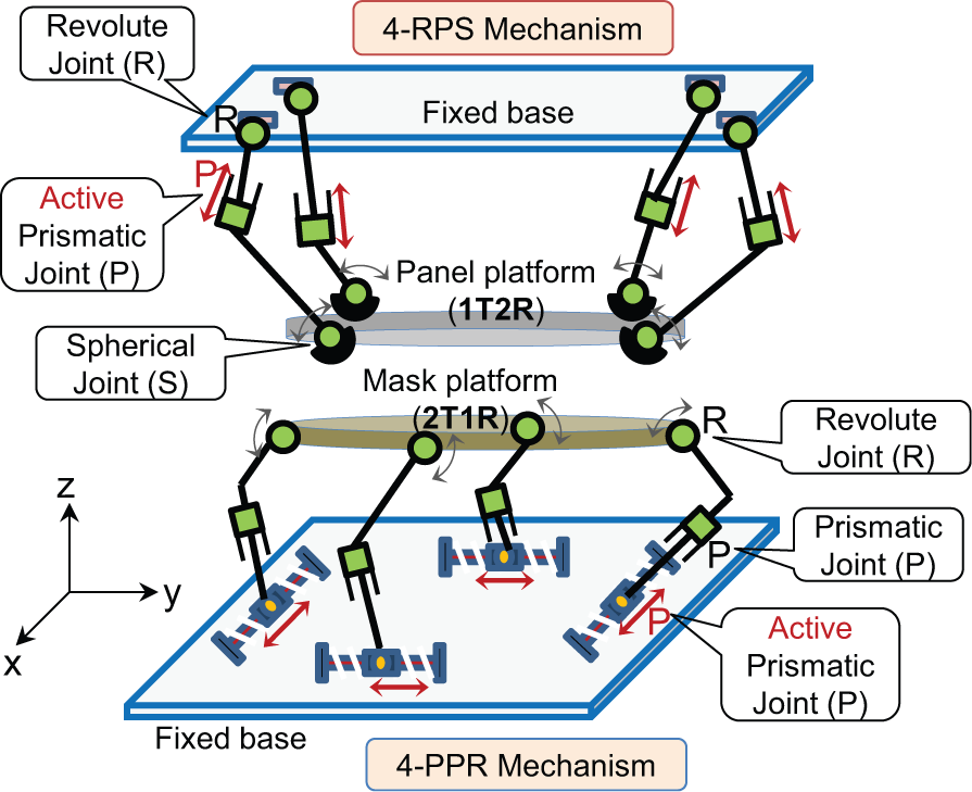
Schematic representation of the hybrid positioning mechanism.
In fact, three limbs with three joints are enough to implement the 3-DOF motion of the moving platform in the task space. However, the larger the display panel size becomes, the greater payload the alignment system should carry. This problem can be resolved by extending the number of driving axes in the joint space, as depicted in Figure 1, where one more limb with an active joint is added to both the parallel mechanisms. Then, in addition to the payload increase, the overall stiffness of the positioning mechanism will improve just as much. As a result, the mask handling system in Figure 1 can be equipped as a 4-PPR type with the four limbs of prismatic–prismatic–revolute joints and the panel handling system as a 4-RPS type with revolute–prismatic–spherical joints.
Depending on the manufacturing equipment in a FPD production line, the visual alignment system can be integrated in diverse forms such as for evaporation, lithography, printing, probing, and so on. However, their functions are fundamentally the same in the respect that the pattern mask is to be aligned to the glass panel. For example, the hybrid visual alignment system in Figure 1 can be established and operated as shown in Figure 2, where the pattern mask is mounted on the lower platform and the glass panel is transferred to the interior of the equipment from the previous station by an extra handling robot. Prior to the alignment tasks, the glass panel should be made flat by the panel stretcher mounted on the same moving platform, and the pre-alignment process is itself preceded by having the alignment marks that are engraved on the mask and panel put in the visible area of the vision cameras. How to handle and fix the flexible panels belongs to another important issue. Related to this, such as the sheet–panel locating algorithm in the study by Cai 14 is considerable as a possible approach. Then, it is followed by the sequence of image acquisition, image processing, alignment mark recognition, extraction of the mask–panel misalignment, and the error compensation control.
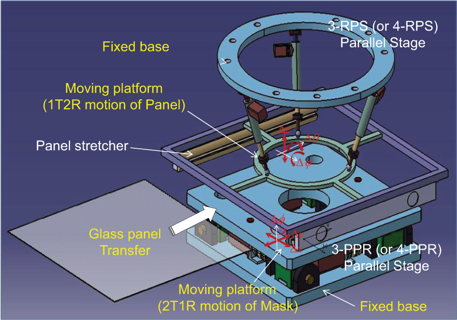
Establishment of the spatial visual alignment system.
The control flow in Figure 3 describes how the hybrid alignment system works until the final alignment error meets the specified tolerance. Two critical issues about implementing the vision-based control system at this point are raised in this article. The first one is to find the inverse kinematic solution of the hybrid mechanism, which is actually the prerequisite to determine the moving distances of the active joints needed to compensate for arbitrary alignment errors. The second one is how to get the spatial misalignment between mask and panel, as depicted in Figure 4. The acquisition of misalignment must be done in real time according to the visual control period, the details on which can be found in the study by Kwon et al. 9 In case of two-dimensional alignment systems, two vision cameras are enough to extract the in-plane misalignments (Δx, Δy, Δφ) by looking at the alignment marks on mask and panel. However, the remaining misalignments along the other axes (Δz, Δθ, Δψ) must be given to realize the spatial misalignment compensation control.
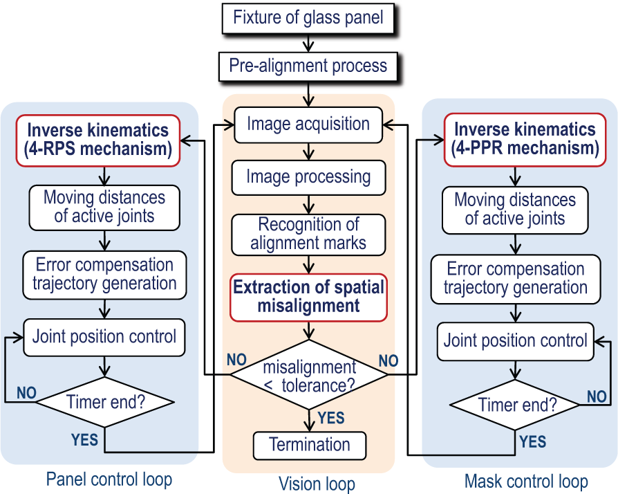
Visual control flow of the hybrid visual alignment system.
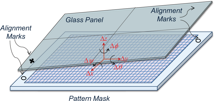
Spatial misalignments between mask and panel.
As far as these two issues are answered, the visual control loop in Figure 3 can be implemented by applying the results in our previous works, which include the fast alignment mark recognition algorithm in terms of the geometric template matching (GTM) 8 and the Kalman filter–based fine control scheme. 9
How to determine the displacements of active joints
In the two parallel positioning mechanisms in Figure 1, the prismatic joints connected to the lower base and the intermediate ones in the upper limbs correspond to the active joints driven by electrical motors. The other ones are passive joints. Since both of the moving platforms have 3-DOF mobility in different directions, the combined motion of the dual mechanisms enables the correction of the 6-DOF misaligned pose between mask and panel. As a good example of adopting the notion of the hybrid manipulation, the position mechanism and the orientation mechanism were decoupled from one another in the hybrid kinematic machine. 15
Inverse kinematics of 4-PPR mechanism
By adding an extra limb to the 3-PPR parallel mechanism widely accepted in the current alignment systems for moving pattern masks, the 4-PPR type shown in Figure 5 consists of four limbs with PPR joints, moving platform, and fixed base. The moving platform denotes the 2T1R motion in the task space, the same as the 3-PPR one. Although the extra limb is advantageous in many aspects such as payload, stiffness of the mechanism, and control resolution, it may invoke mechanical lock due to the actuation redundancy if the four limbs fail to move in a synchronous way. To avoid this problem, it is necessary to determine the displacements of active joints according to the exact kinematic solutions.
Schematic representation of the 4-PPR parallel mechanism.
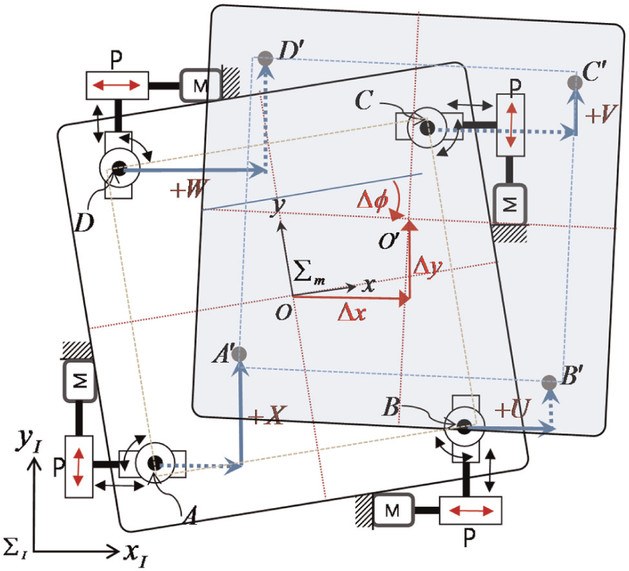
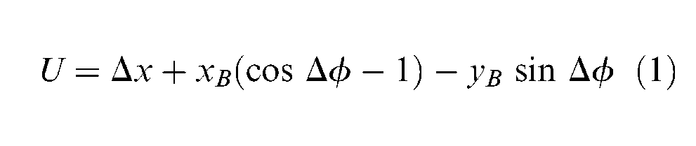
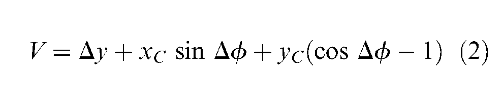
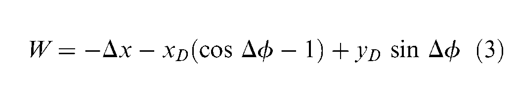
The relationship between the in-plane misalignments (Δx, Δy, Δφ) and the corresponding joint movements to compensate for them is described in Figure 5, where the position vectors of the last revolute joints (A, B, C, D) connected to the moving platform are defined as
Inverse kinematics of 4-RPS mechanism
The schematic of the 4-RPS mechanism for moving glass panels is shown in Figure 6, where the medium prismatic joints are motor-driven active ones, and the glass panel and peripherals are to be mounted on the platform. Like the 4-PPR mechanism in the former section, it also has an actuation redundancy in the joint space. The 1T2R mobility of the moving platform can be confirmed by applying the Gruebler criterion 10 as
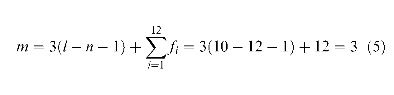
where m is the DOFs of the moving platform, l is the number of links, n is the number of joints, and fi is the DOFs of the ith joint.
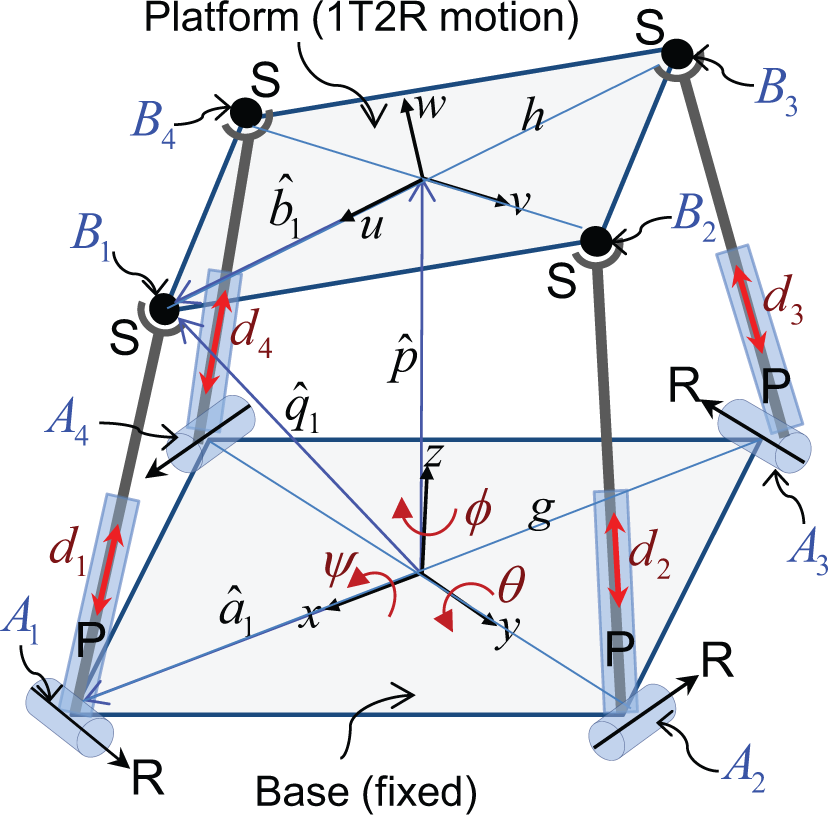
Schematic representation of the 4-RPS parallel mechanism.
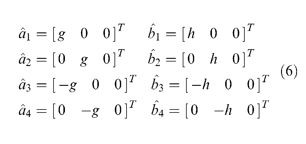
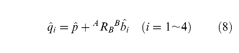
By extending and combining the results for the 3-RPS or 3-PRS mechanisms,11,12,15 the inverse kinematic solution of the 4-RPS mechanism is found. First, the position vectors in Figure 6 are defined as
If we let the magnitudes of
And if we consider the successive transformation of the moving uvw-coordinate system at the platform with respect to the fixed xyz-coordinate system at the base, the orientation of the platform with respect to the base can be defined by the direction cosine matrix
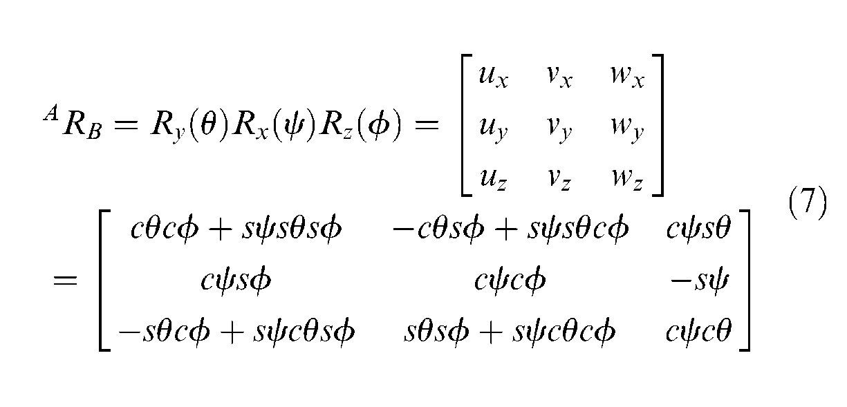
Then, the position vectors of the spherical joints are given by
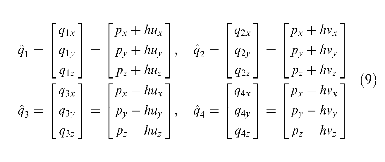
Here, it is considered that the prismatic (P) joints have 1-DOF translations (d1–d4), the spherical (S) joints 3-DOF rotations, and the revolute (R) joints 1-DOF rotations. Hence, as denoted in Figure 6, if the direction of revolute joints is made perpendicular to the xy-axes, the following constraints are generated
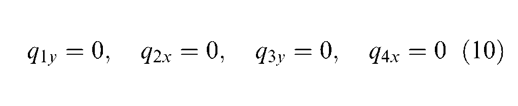
And we have the following three relationships by substituting equation (10) into equation (9)

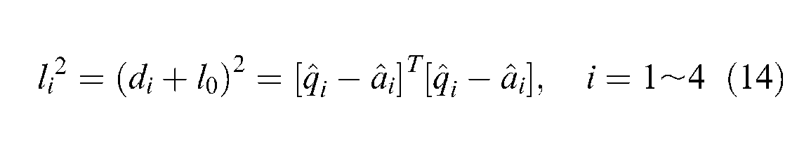
In Figure 6, if we let the original length of the limbs be l0 and the displacements of the active prismatic joints be d1–d4, the variable lengths of the four limbs can be found by
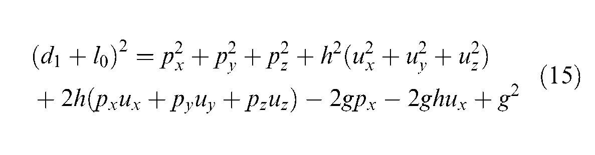
By utilizing equations (6)–(10), equation (14) can be expanded as follows
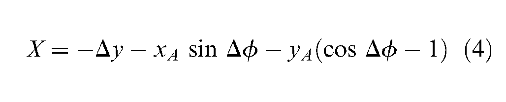
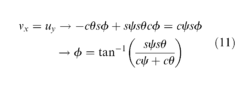
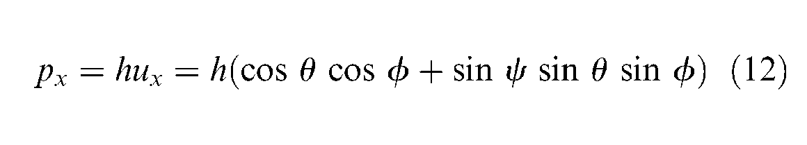
Note that the orientations (θ, ψ) of the platform are equal to the spatial misalignment components (Δθ, Δψ) from the measurement system. Then, the orientation φ and the xy-axes components of the vector
How to extract the spatial misalignments
Vision-only-based measurement
In order to realize the spatial hybrid alignment system, it should be equipped with a proper measuring device to extract the spatial misalignments in the 3D space. First of all, the in-plane misalignments designated in Figure 5 can be determined if the two images which include the alignment marks on mask and panel are given from any two cameras at different locations. The details on the image processing required to get the centroids of the marks can be consulted in the study by Kwon and Hwang.
8
As a result, in Figure 7, when the centroids of the two marks, (L1, L2) on the mask and (C1, C2) on the panel, are equivalent to
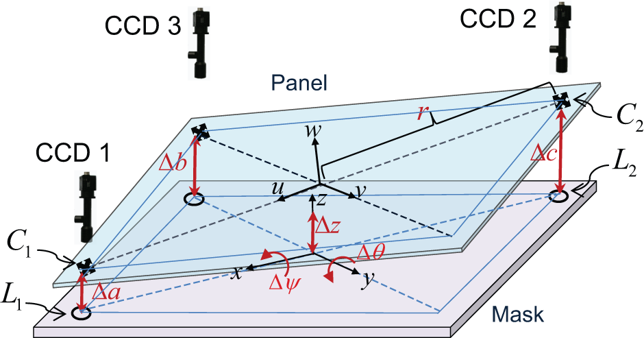
Measurement of spatial misalignments using three in-plane cameras.
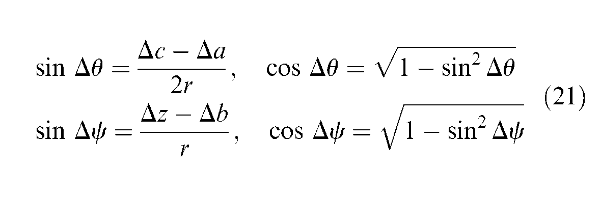
Usually, the vision camera images are two-dimensional without any depth information. However, as shown in Figure 7, if the vertical distances (Δa, Δb, Δc) between the two alignment marks on mask and panel can be extracted in the three different camera locations, the spatial misalignments for the other directions can be determined by
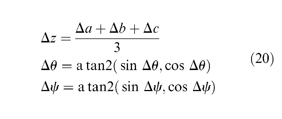
with
As far as the depth information of the marks is reliable and the flatness of the glass panel is guaranteed, this vision-only method is advantageous in that it just requires adding an additional in-plane camera to the current planar alignment systems and putting the alignment keys in the third place on mask and panel.
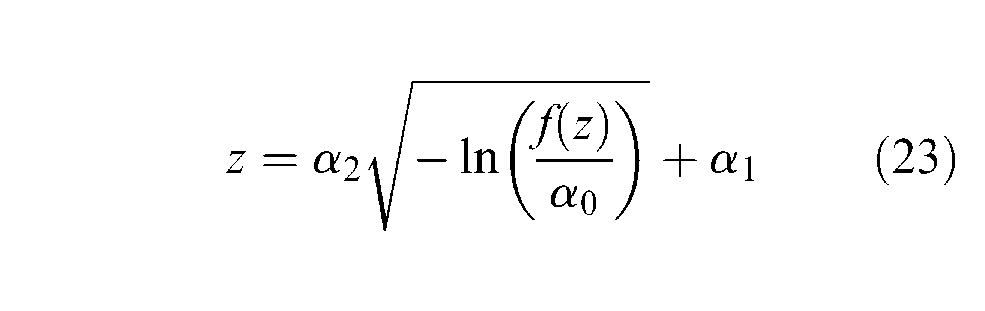
Now, to find the depth of a mark from the fixed cameras, we apply the notion of focus value widely used in the autofocusing problems.16,17 As an example is indicated in Figure 8, when the depth of an object is varied with respect to the fixed position of a camera, the focus value exhibits a Gaussian distribution around the in-focus value
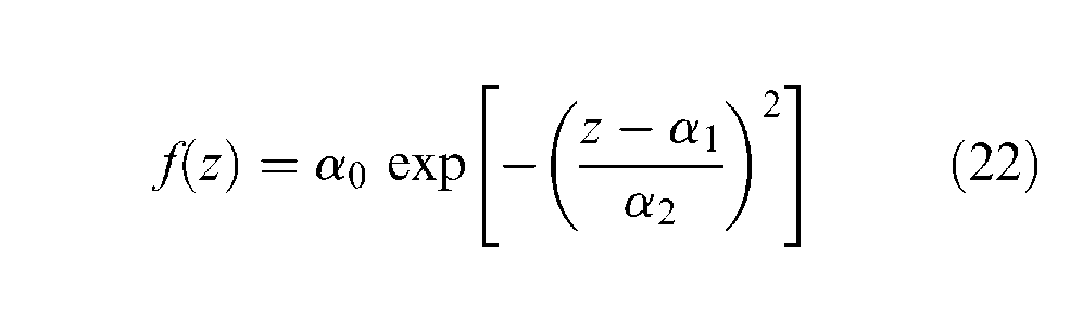
where α0 is the maximum focus value of the Gaussian curve (usually normalized as 1), α1 is the average of depth at the maximum in-focus value, and α2 is the variance. Taking the inverse of the above function results in the depth of the object as the function of focus values
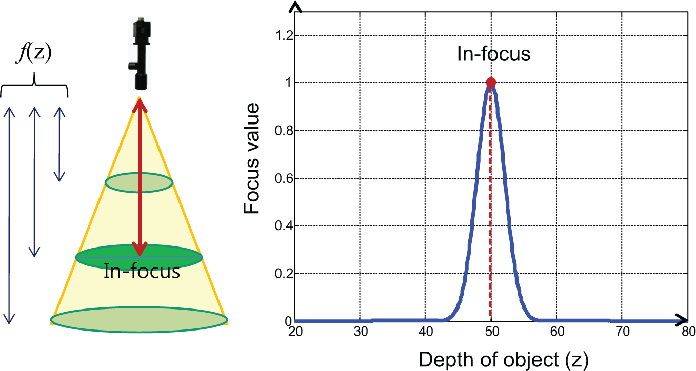
Gaussian distribution of focus value (an example of in-focus depth of 50 mm).
Thus, if the three parameters α0, α1, and α2 are experimentally identified for a specific camera setup, the Gaussian model can be used to get the focus value of each alignment mark in real time while the mask and panel are moving. Since the pattern mask in Figure 7 has no vertical motion, the circular marks on it are stationary in depth and focus value. That is, only the cross marks on the panel contribute to the variation of the focus value. Then, by identifying the depth of the cross marks, the vertical distances (Δa, Δb, Δc) at the designated locations can be readily obtained and the corresponding spatial misalignments by equation (20).
Actually, the set of rotational misalignments in equations (19) and (20) does not follow the general roll–pitch–yaw angle sequence. However, since the rotations about the individual axes are very small in the real applications of visual alignment systems, the rotational matrix in equation (7) holds for any sequence of rotations, and the inverse kinematic solutions in equations (15)–(18) are valid. In the suggested hybrid spatial alignment system, the mask handling 4-PPR positioning stage is in charge of compensating for the in-plane misalignments (equation (19)), and the other spatial misalignments (equation (20)) will be done by the panel handling 4-RPS stage.
Experiment
Instead of building a prototype of the hybrid spatial alignment system, we have utilized the planar alignment system in Figure 9 established in the studies by Kwon and Hwang 8 and Kwon et al., 9 where the moving platform of 4-PPR stage is considered as the pattern mask itself, and the glass panel is fixed without a motorized stage and the three charge-coupled device (CCD) cameras are equipped to confirm the effectiveness of the Gaussian model–based method in the above in extracting the spatial misalignments. For the pattern recognition of the marks, the GTM 8 has been applied.
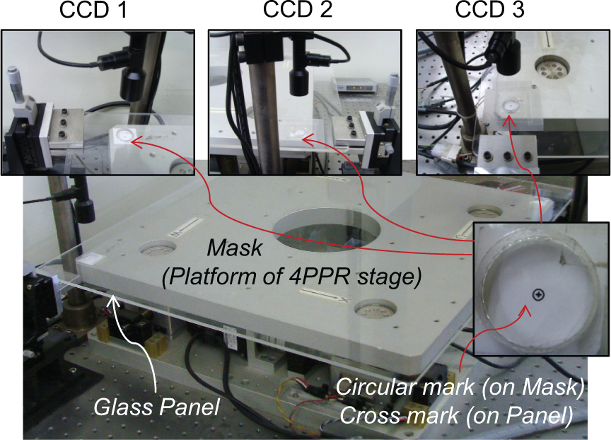
Experimental setup.
In order to establish the Gaussian model in equation (22) for each camera, the focus value distribution must be given along the depth variation from the camera. In fact, the focus values are sensitive to environmental factors such as light, noise, and the printing quality of the marks as well as the camera characteristics. In Figure 9, the camera height is fixed and the depth of the circular marks is also fixed because the platform is stationary in the vertical direction. Only the depth of the cross marks is varied as the glass panel moves vertically.
The focus value of a mark is closely concerned with the number of pixels in the binary images shown in Figure 10, which has the maximum at the in-focus position. In the experimental setup, the focus values have been measured at 15 data points along as the glass panel is moved upward 500 × 500 µm from the in-focus position where the depth is 65 mm. The microscopic movement was made by using a manual microstage. Finally, the distribution of the focus values and the half of the identified Gaussian curves are indicated in Figure 11 for the three cameras, where the focus values correspond to the average of 10 times measurements at the same vertical position.
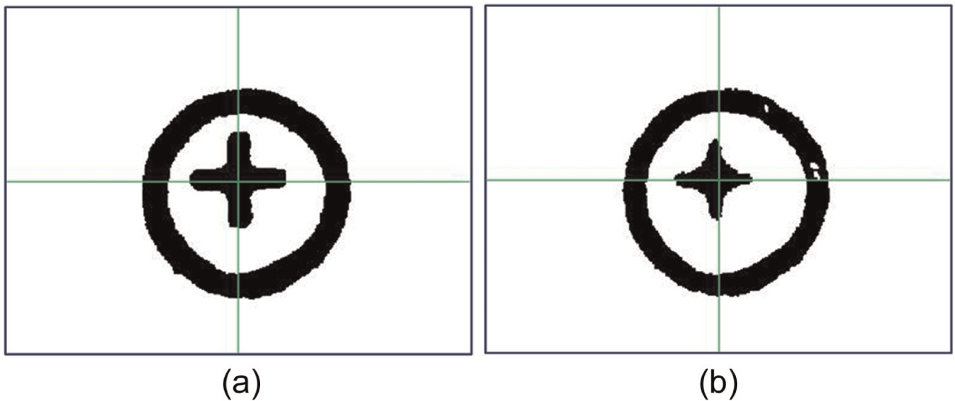
(a) In-focus image and (b) out-of-focus image.
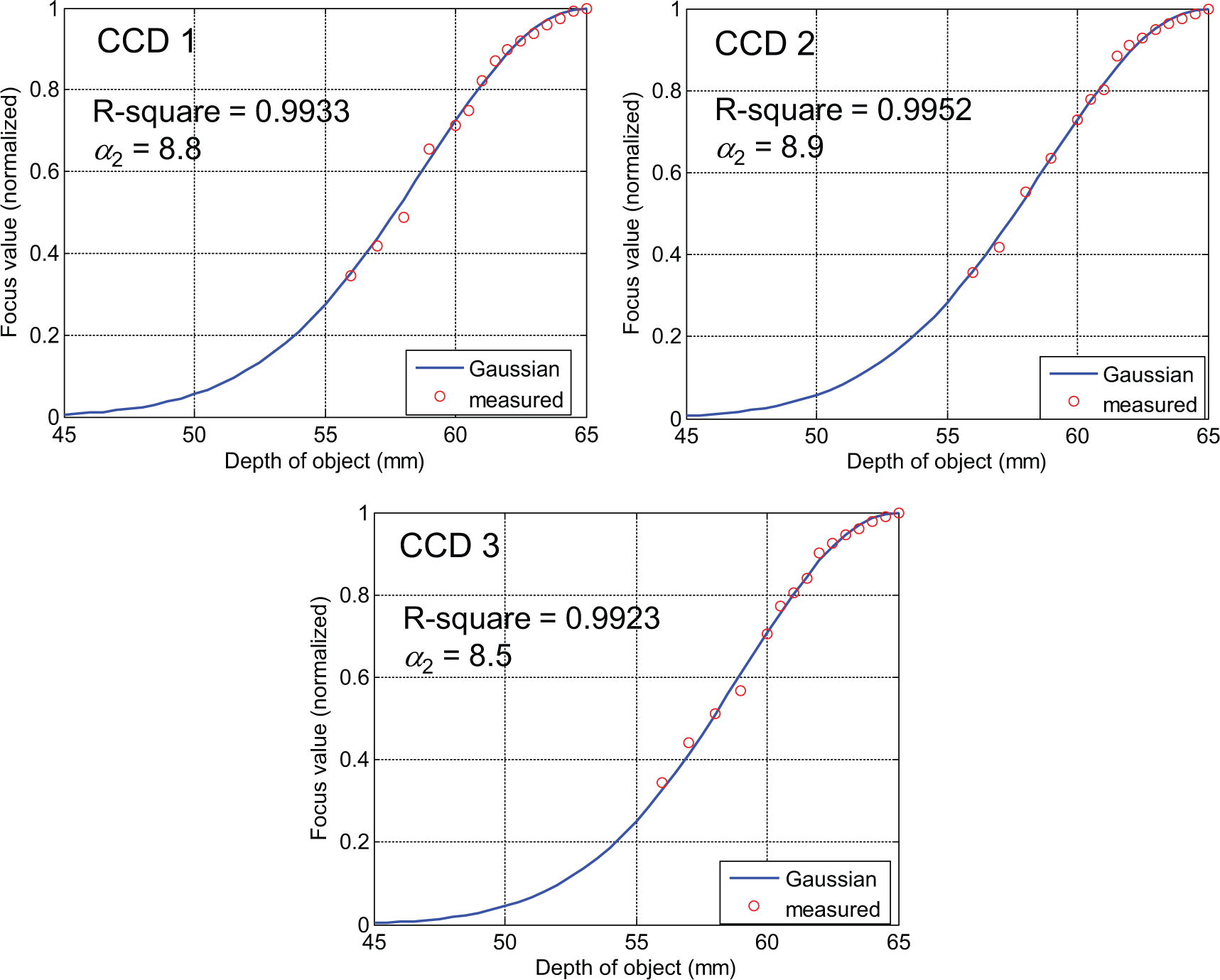
Measured focus values and the identified Gaussian models.
In performing the data matching to establish the Gaussian models, the Levenberg–Marquardt method 17 was used and the reliability of the data matching was evaluated by the R2 measure
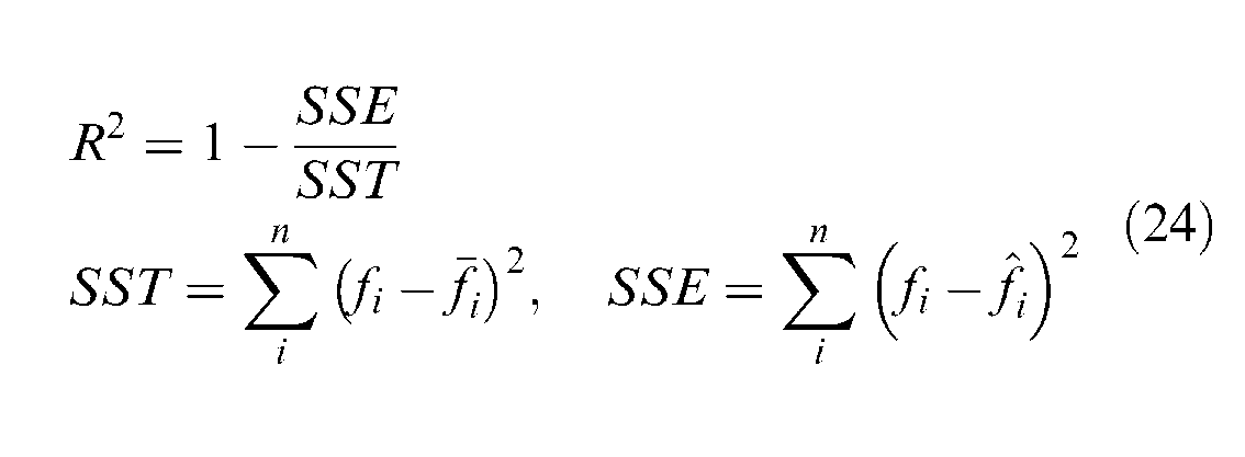
where n is the number of data points, fi is the measured focus value,
Before running the alignment system to confirm the effectiveness of the suggested method, the vertical distances between mask and panel were initially set as (Δa, Δb, Δc) = (2, 1, 3 mm) at the three camera locations to make arbitrary spatial misalignments. As soon as the 4-PPR positioning stage becomes activated, the centroids of the two marks on mask and panel are aligned, as shown in Figure 10, and the in-plane misalignments (Δx, Δy, Δφ) are converged to 0, as displayed in Figure 12, while the remaining spatial misalignments (Δz, Δθ, Δψ) almost keep the initial values. Although this is not the case of real spatial alignment experiment, it is good enough to validate the spatial misalignment extraction method in terms of the focus value Gaussian model.
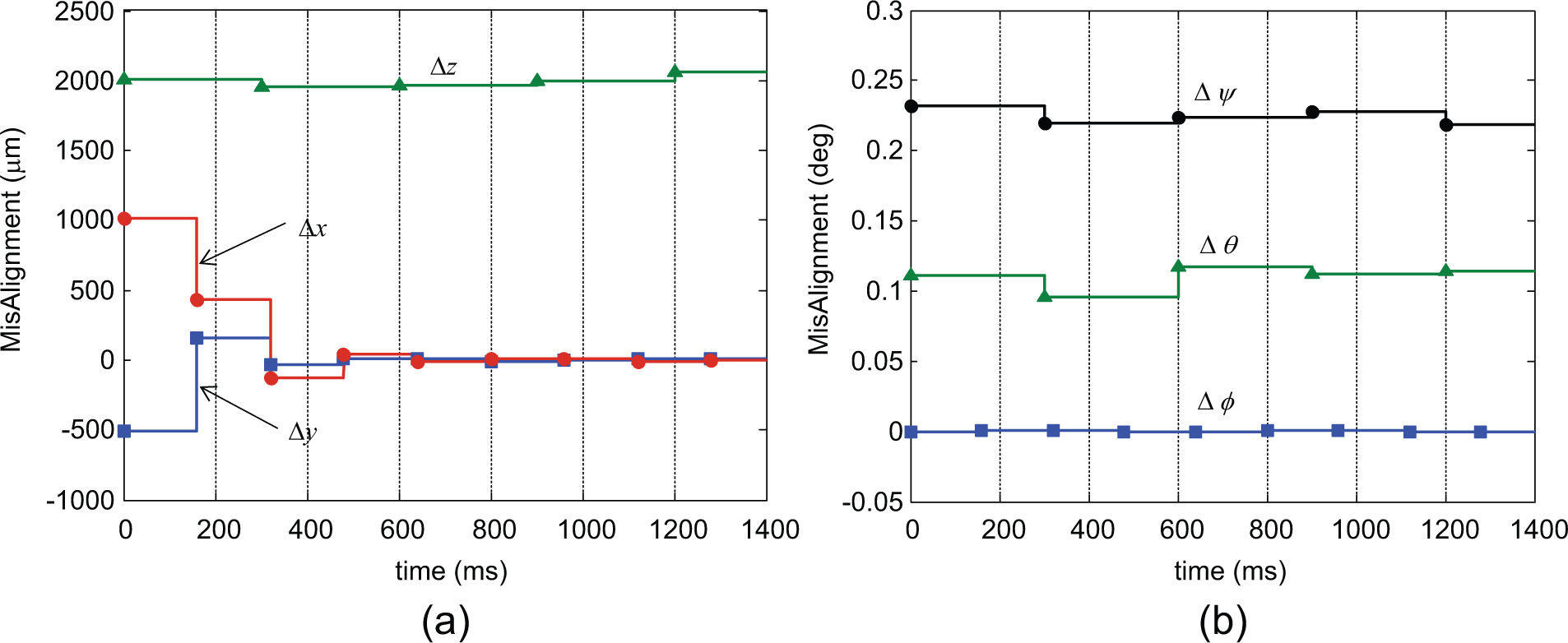
Measurement of spatial misalignments: (a) position misalignments and (b) orientation misalignments.
Conclusion
In a near future, spatial visual alignment system technology is expected to emerge as a hot issue for manufacturing next-generation FPDs. This article suggests a hybrid-type spatial alignment mechanism to achieve a complete alignment between mask and panel in the 3D space, where two critical issues for the operation of the visual control system were answered. First, the inverse kinematic solutions for the decoupled parallel mechanisms provide exact displacements of active joints to compensate for arbitrary spatial misalignments. Second, the vision-only-based measurement of misalignments in terms of the Gaussian model of focus values is promising because it just requires adding one more camera to the current in-plane alignment systems.
Footnotes
Declaration of conflicting interests
The authors declare that there is no conflict of interest.
Funding
This work was supported by the National Research Foundation of Korea under grant number 2012R1A1B3003886.